PBT VALOX DR48
SGN GP 48Y0270 000 标签组件说明书
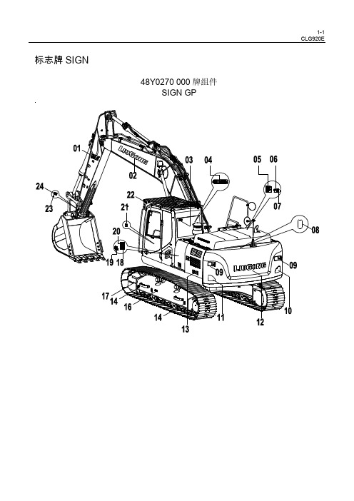
34E0139 005 回转平台总成
REVOLVING FRAME AS
件号 ITE M
部件号 PART NO.
1 34E0139(A)
2 34E0称
回转平台总成 (A) 回转平台总成 (B)
PART NAME
REVOLVING FRAME AS(A) REVOLVING FRAME AS(B)
铭牌 铭牌 噪声标贴 上下机器警告标志 右标贴 蓄能器注意标志 加燃油安全标志 警告标志 柴油标志 警告标志 警告标志 电瓶危险标志 安全标贴 触碰警告标志 安全标志 警告标志 警告标志 操作注意标志 电源安全标志 自动怠速警告标志 警告标志
PART NAME
数量 Q'T Y
服务 代码 S.C
PIN NAMEPLATE 1
PART NAME
WASHER WASHER BOLT SCREW MOUNTING SUPPORT HOLDER REARVIEW MIRROR WASHER REAR MIRROR BLOCK STAY NUT HANDRAIL WASHER BOLT
数量 Q'T Y
服务 代码 S.C
适用机号 SERIAL NO.
18 74A4420 001 润滑图
19 74A4470 000 标贴组件
20 74A1271 000 润滑维护示意图
21 74A4043 000 标贴 22 10A8534 001 铭牌 23 01B0012 000 铆钉 24 10A5048 005 铭牌 25 74A3161 001 安全标贴 26 74A3082 000 冷却液安全标志 27 74A4459 000 标贴 28 74A3090 000 安全标贴 29 74A6903 001 噪声标贴 30 74A3094 000 前窗注意标志 31 74A1837 000 操纵示意图
颜色编号一览表
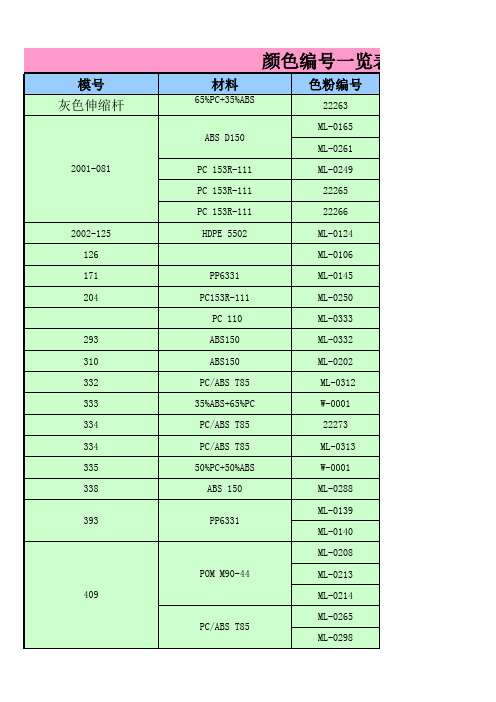
ML-0264 ML-0257 ML-0248 ML-0253 ML-0259
ML-0256 ML-0260 22269 22268 ML-0263 ML-0262 ML-0266 ML-0329 ML-0330 RAL 1015 冷灰色 ML-0268 ML-0269 ML-0270 ML-0267 22272 22270 ML-0185 ML-0274 MF-0001 22270 22272 ML-0182 ML-0182 ML-0182 ML-0169 ML-0182 ML-0277 ML-0306 ML-0289
PC201
ABS 150 ABS 150 PVC 50A PC 3413R PC 3412R PC 3412R
TPE 215B-61AN
PC 3412R
PBT-Valox 357
PC 201
PC 201 ABS D150 PC/ABS LG9000
PC/ABS LG9000
PC/ABS T85 PC/ABS T85 PC/ABS T85 PVC 60 A
PP6331
LLDPE 3224 PVC60A
ABS D-150 HDPE 5502 HDPE 5502 HDPE 5502 ABS D-150 PC 241R
PBT DR48-1001
PC 123R ABS 717C ABS 717C ABS 717C ABS 717C ABS D-150 RTP 300 TPE10 PC/ABS FR3010 PC 500R PC/ABC C6600 TPV 251-80W232 PC/ABS FR3010 RTP 300 TPE10 PC 201 PC 201 PC 201 PC 201 PC 201 PA+15%GF(J132NH) PA+15%GF(J132NH) PC/ABS FR2010
FLAMMA 吉他综合效果器FX150 说明书
www.flShenzhenFlammaInnovationCo.,Ltd
目录
注意事项-----------------------------------------------------------------------------------------------------------01 性能概述-----------------------------------------------------------------------------------------------------------02 主面板说明----------------------------------------------------------------------------------------------------03-04 接口面板说明-------------------------------------------------------------------------------------- -----------05-06 应用场景连接说明------------------------------------------------------------------------------------ --------07-12 连接吉他功放后级+吉他箱体--------------------------------------------------------------------------------07 连接全频设备 - -----------------------------------------------------------------------------------------------08 全频+非全频设备混合连接 ----------------------------------------------------------------------------------09 连接吉他音箱的INPUT - -------------------------------------------------------------------------------------10 连接吉他音箱的FXLOOP------------------------------------------------------------------------------------11 四线接法 -----------------------------------------------------------------------------------------------------12 基本操作------------------------------------------------------------------------ ------------------------------13-19 开机 ----------------------------------------------------------------------------------------------------------13 主界面--------------------------------------------------------------------------------------------------------13 编辑界面-----------------------------------------------------------------------------------------------------14 选择预置音色--------------------------------------------------------------------------------------------15-17 编辑预置音色 ------------------------------------------------------------------------------------------------18 编辑效果链顺序----------------------------------------------------------------------------------------------19 预置音色保存------------------------------------------------------------------------------------------------19 调音器-------------------------------------------------------------------- -----------------------------------------20 LOOPER乐句循环功能--------------------------------------------------------------------------------------21-22
KUTAI ADVR-08 Universal Hybrid Analog-Digital Volt

KUTAI ELECTRONICS INDUSTRY CO., LTD.TEL : +886-7-8121771FAX : +886-7-8121775Website : Headquarters : No.3, Lane 201, Chien Fu St., Chyan Jenn Dist., Kaohsiung 80664, TAIWANADVR-08Universal Hybrid Analog-Digital Voltage Regulator Operation ManualAn Universal Hybrid Analog/Digital 2 lines sensing 8 Amp AVR with multiple power input capability such as Full Harmonic (Compound Windings), Harmonic + Auxiliary Winding, PMG and SHUNT.Compatible with Leroy Somer* R438, R448, R449 and more.Use with KUTAI IVT-1260 / IVT-2460 add-on module can boost generator motor starting capacity.SECTION 1 : SPECIFICATIONSensing Input (E1, E2) Static Power DissipationVoltage 110 - 480 Vac, 1 phase Max.6 watts90 - 130 Vac @ 110 Vac180 - 260 Vac @ 220 Vac Burden in SHUNT & PMG Wiring340 - 520 Vac @ 380 Vac 880 VA @ power input 110 Vac Frequency 50/60 Hz, DIP switch setting 1760 VA @ power input 220 VacPower Input (X1, X2, Aux1)Quadrature Droop Input (S1, S2, S3)Voltage 40 - 300 Vac, 1 phase / 3 phase CT 5A (S1-S2) or 1A (S2-S3) greater than 5VA Frequency 50 - 500 Hz Max. +/- 5% @ P.F +/- 0.71 phase (X1、X2) / 3 phase (X1、X2、Aux1)Analogue Voltage Input (A1, A2)Auxiliary Input (Aux1, Aux2)Input resistance greater than 2K ohmsVoltage 40 - 300 Vac, 1 phase Max. Input +/- 5 VdcFrequency 50 - 500 Hz Sensitivity +/- 25% Generator Volts (adjustable)Excitation Output (F+, F-)Under Frequency Protection (Factory Presets) Voltage Max. 63 Vdc @ power input 110 Vac 50 Hz system presets knee point at 45 HzMax. 125 Vdc @ power input 220 Vac 60 Hz system presets knee point at 55 Hz Current Continuous 8AIntermittent 12A for 10 secs. Over Excitation ProtectionResistance ≧8 ohms @ power input 110 Vac Set point 170 Vdc +/- 5 % @ power input 220 Vac ≧16 ohms @ power input 220 VacFuse Spec. Slow blow 5 x 20mm S505-10A Voltage Thermal DriftLess than 3% at temperature range -40 to +70 ˚C External Voltage Adjustment (VR1, VR2)Max. +/- 4% @ 500 ohms 1 watt potentiometer Under-Frequency Knee Point Thermal DriftMax. +/- 8% @ 1K ohm 1 watt potentiometer Less than +/- 0.1 Hz at -40 to +70 ˚CVoltage Regulation EnvironmentLess than +/- 0.5% ( with 4% engine governing ) Operating T emperature -40 to +70 ˚CStorage T emperature -40 to +85 ˚CBuild Up Voltage Relative Humidity Max. 95%6 Vac 25 Hz residual volts at power input terminal Vibration 3 Gs @ 100 - 2K HzSoft Start Ramp Time Dimensions4 seconds +/- 10% 171.0 (L) x 120.0 (W) x 50.0 (H) mmTypical System Response WeightLess than 20 milliseconds 820 g +/- 2%EMI SuppressionInternal electromagnetic interference filtering___________________________________________________________________________________________ 2ADVR-08SECTION 2 : OUTLINE / SIZE / INSTALLATION REFERENCEFlag Terminal (“Fast-On” terminal)Figure 1Outline Drawing___________________________________________________________________________________________ ADVR-08 3___________________________________________________________________________________________ 4ADVR-08SECTION 3 : DIP SWITCH PROGRAMMING & VR ADJUSTMENTSU/F LEDO/E LEDSet fully50 Hz System : 40 to 51 Hz (Lowest position)60 Hz System : 50 to 61 Hz (Lowest position)(See TRIM)This adjustment allows some control over the generator voltage dip when applying load.It is typically used to compensate for turbo lag, leaving the generator to operate below the UFRO knee point setting. The voltage droop ratio can be set using the DIP adjustment. The range is 10 to 3 V/Hz.HZ HZ___________________________________________________________________________________________ ADVR-085SECTION 4 : WIRING CONNECTIONSExciter fieldPMGS2-S3 N:1AS 2-S 3 N :1AS 1-S 2 N :5A C.T Stator windingsS2-S3 N:1AS1-S2 N:5A Exciter fieldS2-S3 N:1AS1-S2 N:5A C.TFigure 2 Single & Three Phase PMGFigure 3 Three Phase AuxiliaryWinding (Full Harmonic)Figure 4 Auxiliary & HarmonicFigure 5 Self-Excited (SHUNT)Exciter fieldFigure 6ADVR-08 & IVT-1260 / IVT-2460 Wiring Connection※Use only the replacement fuses specified in this user manual.※Appearance and specifications of products are subject to change for improvement without prior notice.___________________________________________________________________________________________ 6ADVR-08。
valox典型成型指南[01]
![valox典型成型指南[01]](https://img.taocdn.com/s3/m/91cc0625ccbff121dd368369.png)
为VALOX 树脂的模具选择钢材,与为注塑产品选择树脂一样, 对于应用的效果起着决定性的作用。正如树脂需按方配制,以满 足塑料在应用中的性能要求一样,钢也需合金化,以满足使用中 的特定性能要求。
某些应用需要高硬度和高耐磨性的模具钢,以增强分模线的耐久 性,而其它应用则需要高韧性的模具钢,以抵抗机械疲劳。一般 来说,具有更高硬度和耐磨性能的钢更易脆,而在绝大多数的情 况下,韧性更强的钢,其耐钢与钢磨蚀(粘附磨蚀),与耐玻璃 纤维或矿物充填树脂磨蚀的性能会有所减弱。
200
Wall Thickness, in
VALOX PBT 树脂 • 12-7
Mold Shrinkage, mils/in
图 12-3. 曲线图: VALOX 508 & 553 树脂牌号 一 模具收缩量与壁厚
25
20
15 Cross Flow
10
Flow 5
050
100
150
200
Wall Thickness, in
VALOX 701, 751 resins
VALOX 735, 780 resin
050
100
150
200
Wall Thickness, in
Mold Shrinkage, mils/in
25 Flow Direction
20
15
VALOX 815, 850, 855 resins
10
5
VALOX 830 resin
这些曲线代表了在本指南建议的标准条件下,加工 VALOX 工程热塑性树脂,预期会产生的收缩量。制件的 几何形状和不同的加工条件,可影响收缩量。制件几何形 状的模型测试,可为特定的应用,提供最可靠的数据。有 关收缩量的进一步资料,可以从麻省Pittsfield的GE Plastics 技术服务中心处获得。电话:(800)845-0600
常用塑胶特性表
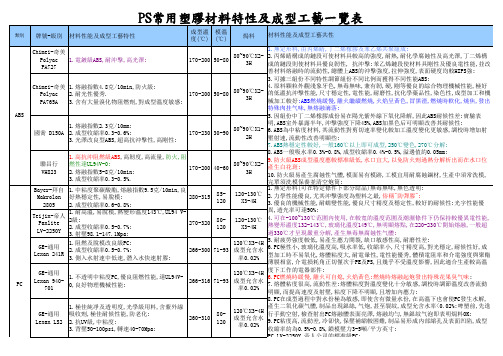
PC LV-2250Y,帝人公司的標准級PC:
動明顯,而提高速度及射壓,粘度下降不明顯,且增加內應力;
8.PC在成型過程中對水份極為敏感,即使含有微量水份,在高溫下也會使PC發生水解,產生二氧化碳气體,制品出現銀絲,气炮,甚至裂紋,成型允含水率<0.02%;啤塑
的9倍,聚碳酯酸和尼龍的3倍,非晶態PET具良好光學透明度,廣泛用于食品包裝領域;
4.PET相對密度1.30-1.38,熔點255-260℃,成型溫度范圍窄,熔融溫度超300℃則發
燒,燃燒時熔融並爆成碎片,火焰呈黃色,有滴落;
一般可不用干燥;
9.POM磨擦系數低,彈性高,易脫模;
10.POM嚴禁與PVC共混加熱,兩者共加熱時有強烈反應,兩者換料須先徹底清除前者;
19.玻纖增強級尼龍回料速度及背壓不宜高,以免玻纖剪斷而破壞並降低物性;
20.玻纖尼龍開機程序:
A.設定料缸溫度在正常操作溫度30℃以下,設定射咀溫度在正常操作溫度,20分鐘后。
Brochure_Plastite_48
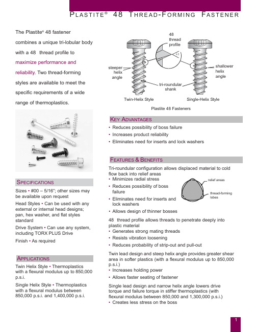
P L A S T I T E® 4 8 T H R E A D - F O R M I N G F A S T E N E R The Plastite® 48 fastenercombines a unique tri-lobular bodywith a 48° thread profile tomaximize performance andreliability. Two thread-formingstyles are available to meet thespecific requirements of a wide48°shallowerhelixangle range of thermoplastics.Twin-Helix Style Single-Helix S tylePlastite 48 FastenersK EY A DVANTAGES• Reduces possibility of boss failure• Increases product reliability• Eliminates need for inserts and lock washersF EATURES &B ENEFITSTri-roundular configuration allows displaced material to coldflow back into relief areasS PECIFICATIONSSizes • #00 – 5/16"; other sizes maybe available upon requestHead Styles • Can be used with anyexternal or internal head designs;pan, hex washer, and flat styles• Minimizes radial stress• Reduces possibility of bossfailure• Eliminates need for inserts andlock washers• Allows design of thinner bossesthread-forminglobesstandardDrive System • Can use any system,including TORX PLUS DriveFinish • As requiredA PPLICATIONSTwin Helix Style • Thermoplasticswith a flexural modulus up to 850,000p.s.i.Single Helix Style • Thermoplasticswith a flexural modulus between850,000 p.s.i. and 1,400,000 p.s.i.48° thread profile allows threads to penetrate deeply intoplastic material• Generates strong mating threads• Resists vibration loosening• Reduces probability of strip-out and pull-outTwin lead design and steep helix angle provides greater sheararea in softer plastics (with a flexural modulus up to 850,000p.s.i.)• Increases holding power• Allows faster seating of fastenerSingle lead design and narrow helix angle lowers drivetorque and failure torque in stiffer thermoplastics (withflexural modulus between 850,000 and 1,300,000 p.s.i.)• Creates less stress on the boss1P L A S T I T E® 4 8 T H R E A D - F O R M I N G F A S T E N E R† C dimension measured with Tri-Flute MicrometerD diameter measured with Standard MicrometerD IMENSIONAL D ATA – I NCH S IZESC DimensionD Dimensionmax-min max-min under3/4"3/4" over(in) (in) (in) #0051.0496 - .0466.0475 - .0445±.015 ±.015#042.0665 - .0635.0635 - .0605±.015 ±.015#132.081 - .078.078 - .075±.030 ±.030#228.092 - .086.089 - .083±.030 ±.030#324.110 - .104.106 - .100±.030 ±.030#420.127 - .121.123 - .117±.030 ±.050#619.147 - .141.143 - .137±.030 ±.050#718.166 - .160.160 - .154±.030 ±.050#816.185 - .179.179 - .173±.030 ±.050#915.199 - .193.193 - .187±.030 ±.050#1014.212 - .206.208 - .202±.030 ±.050#1214.232 - .226.226 - .220±.030 ±.0501/4"10.276 - .270.268 - .262±.050 ±.0505/16"9.345 - .335.335 - .325±.050 ±.050D IMENSIONAL D ATA – M ETRIC S IZES* *soft converted metric sizesC DimensionD Dimension19.05mmmax-min 19.05mmover(mm)1.120.50 1.26 - 1.18 1.21 - 1.13±0.38 ±0.381.590.60 1.69 - 1.61 1.61 - 1.54±0.38 ±0.381.910.792.06 - 1.98 1.98 - 1.91±0.76 ±0.762.260.91 2.34 - 2.18 2.26 - 2.11±0.76 ±0.762.63 1.06 2.79 - 2.64 2.69 - 2.54±0.76 ±0.763.12 1.27 3.23 - 3.07 3.12 - 2.97±0.76 ±1.273.63 1.34 3.73 - 3.58 3.63 - 3.48±0.76 ±1.274.06 1.41 4.22 - 4.06 4.06 - 3.91±0.76 ±1.274.55 1.59 4.70 - 4.55 4.55 - 4.39±0.76 ±1.274.90 1.695.05 - 4.90 4.90 - 4.75±0.76 ±1.275.28 1.81 5.38 - 5.23 5.28 - 5.13±0.76 ±1.275.74 1.81 5.89 - 5.74 5.74 - 5.59±0.76 ±1.276.81 2.547.01 - 6.86 6.81 - 6.65±1.27 ±1.278.51 2.828.76 - 8.518.51 - 8.26±1.27 ±1.27* Plastite 48 fasteners are not available in true metric sizes. The chart above provides nominal inchdimensions converted to millimeters.2P L A S T I T E ® 4 8 T H R E A D - F O R M I N G F A S T E N E RH OLE S IZES P ER P ERCENTAGE OF T HREAD E NGAGEMENT#00-51.0377 0.957.0386 0.980.0395 1.003 .0404 1.026 .0413 1.049.0423 1.074.0432 1.097 #0-42 .0498 1.265 .0510 1.295 .0523 1.328 .0535 1.359 .0548 1.392.0560 1.422 .0573 1.455 #1-32 .0621 1.577.0632 1.605 .0646 1.641 .0658 1.671 .0671 1.704.0683 1.735 .0695 1.765 #2-28 .0743 1.887 .0757 1.923 .0771 1.958 .0785 1.994 .0799 2.029.0813 2.065 .0827 2.101 #3-24 .0855 2.172 .0873 2.217 .0890 2.261 .0908 2.306 .0925 2.350.0943 2.395 .0960 2.438 #4-20 .0970 2.464 .1000 2.540 .1020 2.591 .1050 2.667 .1070 2.718.1100 2.794 .1130 2.870 #6-19 .1180 2.997 .1200 3.048 .1230 3.124 .1250 3.175 .1280 3.251.1300 3.302 .1320 3.353 #7-18 .1370 3.480 .1390 3.531 .1420 3.607 .1440 3.657 .1460 3.708.1490 3.785 .1510 3.835 #8-16 .1440 3.658 .1480 3.759 .1510 3.835 .1550 3.937 .1580 4.013.1620 4.115 .1650 4.191 #9-15 .1570 3.988 .1590 4.039 .1610 4.089 .1640 4.166 .1660 4.216.1680 4.267 .1700 4.318 #10-14 .1700 4.318 .1740 4.420 .1770 4.496 .1810 4.597 .1850 4.699.1890 4.801 .1920 4.877 #12-14.1880 4.775 .1920 4.877 .1960 4.978 .1990 5.055 .2030 5.156.2070 5.258 .2110 5.359 1/4"-10 .2180 5.537 .2230 5.664 .2280 5.791 .2330 5.918 .2380 6.045.2430 6.172 .2480 6.299 5/16"-9.2840 7.214.2910 7.391.2980 7.569 .3050 7.747.3110 7.899.3180 8.077.3250 8.255B OSS D ESIGN R ECOMMENDATIONSThe length of engagement (L) should be 2 to 3 times the fastener’s C dimension. Testing should be done to determine optimal threadengagement on any application with a lower length of engagement.The nominal hole size (hØ) must be established based on the amount of thread engagement (see chart above). For optimum performance, the hole size should provide a minimum 70% thread engagement.The outside diameter of the boss (boss O.D.) should be 2.5 to 3 times the nominal diameter of the screw (C dimension). The boss height should not exceed 2 times the boss O.D. The counterbore width (CB w ) should be slightly larger than the C dimension. Its depth (CB d ) shouldadd‘l hole depth for length tolerancebe 1/4 to 1/2 the thread pitch.REV: 02/08/116125 Eighteen Mile Road Sterling Heights, Michigan 48314acumentnorthamerica .com。
艾森特48英寸防静电工作台使用手册说明书

Owner’s ManualPart Number: ESDW-4830-1000For Your SafetyRead and understand the entire manual before use48” ESD WORKBENCH®TABLE OF CONTENTS ContentsS UPPORT (2)D ISCLAIMER (2)DIMENSIONAL DRAWING (3)SPECIFICATIONS (3)TOOLS NEEDED (3)COMPONENT IDENTIFICATION (4)INSTALLATION (5)INSTALLATION CONTINUED (6)ESD ELECTRICAL CIRCUIT (7)CARE AND CLEANING (7)TROUBLESHOOTING (8)WARRANTY (9)SupportSupport is available through the following methods:By Phone from 8:00 AM to 5:00 PM CST. 651.213.1333By Email*********************************By Mail 10152 Liberty Lane, Chisago City, MN 55013By Web DisclaimerDISCLAIMER: Kendall Howard LLC. endeavors to make this manual accurate and complete. However, Kendall Howard LLC makes no representations or warranties of any kind, expressed or implied, about whether the use of products contained herein would infringe any rights or the correctness, accuracy or reliability of the information contained herein or that said information covers all details, conditions, or variations. The information herein does not provide for every possible contingency in connection with the installation or use of the product(s). The information contained in this document is subject to change without notice or obligation. Kendall Howard LLC assumes no responsibility for the accuracy, completeness or reliability of the information contained in this document. Any reliance placed on the information is therefore strictly at your own risk.Dimensional DrawingSpecificationsOverall Dimensions 48” Wide x 30” Deep x 30” Tall (at lowest setting) Worksurface Dimensions 30” Deep x 48” LongWeight 115 lbs. (253 kg)Workbench Support Color Gloss Black Powder CoatWorksurface Color Cloudy GrayTools NeededPhillips Screwdriver or Cordless DrillComponent IdentificationWhat’s included?Work Surface 48” x 30” (1)Leg Assembly (2) Part Number: A-1065 Part Number: A-1075Cross Bar (2) Gusset (2)Part Number: A-1077 Part Number: A-1080Pan Head Screw (38) ESD Grounding Boot (1) Part Number: HW-PHS-006 Part Number: A-1084Self-Adhesive Cable Tie Mount (5) 6” Cable Tie (5)Part Number: CP-1045 Part Number: CP-1019InstallationStep 1:Cut and remove the two plastic banding and any shrink wrap material, remove top from crate packaging & remove components.Step 2:Place the Work Surface on its top on a clean and sturdy working area. Locate the two leg assemblies and 16 Pan Head Screws. Install the screws 6 into the inside of each Leg Assembly and 2 on the outer side.Step 3:Locate the Gussets. Place the bottom of the slotted end of the Gusset in to the slot guide of the Leg Assembly, Locate 8 Pan Head Screws. Install Screws through the Gusset and into the Work SurfaceInstallation ContinuedStep 4:Locate the Cross Bars and 14 Pan Head Screws. Install 7 screws into each cross bar as shown below.Step 5:Determine how the Workbench will be grounded. If using the ESD Grounding Boot, proceed to step 6. If an Earth ground is needed proceed to step 7.Step 6:Install the Grounding Boot on the right rear Leg Leveler. Locate the ESD Grounding Boot, and the short, pre-installed grounding wire. Remove the Philips head screw from the Ground Boot, place the lever stem through the bottom of the Grounding Boot, latch the top of the Grounding Boot, strip and install the ground wire between the boot halves. Reinstall the Phillips screw. Flip table over and adjust the leg levelers until workbench is level. Use the provided cable tie mounts to secure the ground wire to the table leg.Step 7:Locate the 10’ pre-installed grounding wire. Determine where the Workbench will be installed. Flip table over and adjust the leg levelers until workbench is level. Connect the 10’ Earth ground wire to a safe common grounding point. Use the provided cable tie mounts to secure the ground wire to the table leg.ESD Electrical CircuitWork SurfaceA wire connects the conductive aluminum boot to a common ground located in worksurface. A wire is connected from the common ground to an external Earth ground wire. A wire is connected from the common ground to the wrist strap ground point.Care and CleaningPainted SurfacesAll painted surfaces can be cleaned with a non-abrasive, non-ammonia or non-bleached based cleaner. Do not use soap or detergents on exposed metal surfaces, leg levelers or on the work surface. The soap may leave a residue that will insulate the surface from ESD grounding. Wipe down all cleaned surfaces with a lint free soft cloth.Leg levelersThree of the four leg levelers are adjustable and non-conductive. They can be cleaned with any non-ammonia or bleached based cleaner. The fourth Leg leveler is equipped with an aluminum conductive boot. This can be cleaned with any non-ammonia or bleached based cleaner.Approved cleaning solutions for ESD surfaces•Desco 10446 Reztore Surface & Mat Cleaner•3M 8001 Antistatic Mat & Table Top CleanerNOTE: Do not use petroleum-based solvents or alcohol to clean any surfaces on this ESD Workbench.TroubleshootingESD non-compliant on work surface & common grounds•Verify that the flooring has a RTT value of 10⁵<10⁹ Ohms resistance.•Verify that the ESD surface has a RTT value of 10⁵<10⁹ Ohms resistance. If it does not, clean and repeat test. If it still does not pass then the surface will need to be replaced.•Verify that that the resistance from the surface to the conductive aluminum boot has a RTG value of 10⁵<10⁹ Ohms resistance. If this RTG value fails proceed to the next step.•Check the RTG value of 10⁵<10⁹ Ohms resistance from the common ground on the work surface to the conductive aluminum boot. If this test passes, replace the ESD surface. If this RTG value fails proceed to the next step.•Check the RTG value of 10⁵<10⁹ Ohms resistance from the ESD wrist strap connection point to the conductive aluminum boot. If this test passes, replace the ESD surface. Ifthis RTG value fails proceed to the next step.•Check the built-in cable to see if it connected or broken. Replace if damaged. Retest RTG value.•Check ground wire connection to the conductive aluminum boot (this is visible underneath the bottom shelf). Replace if damaged. Retest the RTG value.Glossary:•RTT =Resistance to table•RTG = Resistance to groundWarrantyGENERAL: Kendall Howard offers all users of our products the following Limited Warranty against defects in material and workmanship. Please read your Warranty carefully. This Warranty sets forth our responsibilities in the unlikely event of defect and tells you how to obtain resolution.TERMS OF WARRANTY: Kendall Howard products are warranted to be free of defects in material and workmanship. If any part or portion of the Kendall Howard product fails to conform to the Warranty, Kendall Howard, at its option, will furnish new or factory remanufactured products for repair or replacement of that part.WARRANTY EXTENDS TO FIRST PURCHASER FOR USE, NON-TRANSFERABLE: This Warranty is extended to the first person, firm, association, or corporation for whom the Kendall Howard product specified herein is originally sold for use in the United States (the "User"). This Warranty is not transferable or assignable without the prior written permission of Kendall Howard.ASSIGNMENT OF WARRANTIES: Kendall Howard assigns to User any warranties which are made by manufacturers and suppliers of components of the Kendall Howard product and which are assignable, but Kendall Howard makes NO REPRESENTATIONS as to the effectiveness or extent of such warranties, assumes NO RESPONSIBILITY for any matters which may be warranted by such manufacturers or suppliers and extends no coverage under this Warranty to such components.DRAWINGS, DESCRIPTIONS: Kendall Howard warrants for the period and on the terms of the Warranty set forth herein that the Kendall Howard product will conform to the descriptions contained in Kendall Howard final invoices, orders, proposals (as modified) and other Kendall Howard descriptive documents ("Descriptions"). Kendall Howard does not control the use of any Kendall Howard product. Accordingly, it is understood that the Descriptions are NOT WARRANTIES OF PERFORMANCE and NOT WARRANTIES OF FITNESS FOR A PARTICULAR PURPOSE.WARRANTY CLAIMS PROCEDURE: Within a reasonable time, but in no case to exceed thirty (30) days, after User's discovery of a defect, User shall contact Kendall Howard. Subject to the limitations specified herein, a Kendall Howard customer service representative will repair or replace the non-conforming Kendall Howard product warranted hereunder, without charge for materials. User will not be charged for labor if performed within thirty (30) days of product pur chase. In all other instances, User will be charged for labor performed at Kendall Howard’s then current rates. Kendall Howard shal l assume shipping costs for replacement products and return of the defective product to Kendall Howard. Warranty coverage will be extended only after Kendall Howard inspection determines there is a defect as claimed and shows no signs of treatment or use which would void the coverage of this Warranty.WARRANTY PERFORMANCE OF COMPONENT MANUFACTURERS: It is Kendall Howard’s practice, consistent with its desire to remedy Warran ty defects in the most prompt and effective manner possible, to cooperate with and utilize the services of component manufacturers and their authorized representatives in the performance of work to correct defects in Kendall Howard components. Accordingly, Kendall Howard may utilize third parties in the performance of Warranty work, inclu ding repair or replacement hereunder, where, in Kendall Howard’s opinion, such work can be performed in less time, and with l ess expense.ITEMS NOT COVERED BY WARRANTY: THIS WARRANTY DOES NOT COVER DAMAGE OR DEFECT CAUSED BY misuse, improper application, wrong or inadequate electrical current or connection, negligence, inappropriate on site operating conditions, repair by non- Kendall Howard designated personnel, accident in transit, tampering, alterations, a change in location or operating use, exposure to the elements, Acts of God, theft or installation contrary to Kendall Howard's recommendations or specifications, or in any event if the Kendall Howard serial number has been altered, defaced, or removed. THIS WARRANTY DOES NOT COVER installation costs, external circuit breaker resetting or maintenance or service items and further, except as may be specifically provided for her ein, does NOT include labor or shipping costs arising from the repair or replacement of the Kendall Howard product, or any part thereof, or charges to remove same from any premises of User. THIS WARRANTY IS VOID if User alters the product in any way.LIMITATIONS: THIS WARRANTY IS IN LIEU OF AND EXCLUDES ALL OTHER WARRANTIES, EXPRESS OR IMPLIED, INCLUDING MERCHANTABILITY AND FITNESS FOR A PARTICULAR PURPOSE. USER'S SOLE AND EXCLUSIVE REMEDY IS REPAIR OR REPLACEMENT OF THE KENDALL HOWARD PRODUCT AS SET FORTH HEREIN. IF USER'S REMEDY IS DEEMED TO FAIL OF ITS ESSENTIAL PURPOSE BY A COURT OF COMPETENT JURISDICTION, KENDALL HOWARD’S RESPONS IBILITY FOR PROPERTY LOSS OR DAMAGE SHALL NOT EXCEED ONE TIMES THE NET PRODUCT PURCHASE PRICE. IN NO EVENT SHALL KENDALL HOWARD ASSUME ANY LIABILITY FOR INDIRECT, SPECIAL, INCIDENTAL, EXEMPLARY OR CONSEQUENTIAL DAMAGES OF ANY KIND WHATSOEVER, INCLUDING WITHOUT LIMITATION LOST PROFITS, BUSINESS INTERRUPTION OR LOSS OF DATA, WHETHER ANY CLAIM IS BASED UPON THEORIES OR CONTRACT, NEGLIGENCE, STRICT LIABILITY, TORT, OR OTHERWISE.MISCELLANEOUS: NO SALESPERSON, EMPLOYEE OR AGENT OF KENDALL HOWARD IS AUTHORIZED TO ADD TO OR VARY THE TERMS OF THIS WARRANTY. Warranty terms may be modified, if at all, only in writing signed by a Kendall Howard officer. This Warranty is effective as of the date of Kendall Howard receipt of full payment and supersedes all previous warranties Kendall Howard reserves the right to supplement or change the terms of this Warranty in any subsequent warranty offering to User or others. If any provision of this Warranty should be or becomes invalid and/or unenforceable during the warranty period, the remaining terms and provisions shall continue in full force and effect. User must complete the attached User Information Card and forward it to Kendall Howard within thirty (30) days of receipt of the Kendall Howard product. This Warranty is given in and performance hereunder is to be construed under the laws of the State of Nebraska. This Warranty represents the entire agreement between Kendall Howard and User with respect to the subject matter herein and supersedes all prior or contemporaneous oral or written communications, representations, understandings, or agreements relating to this subject.。