parker派克组合阀
Parker PCO2系列气缸保护器用户指南说明书
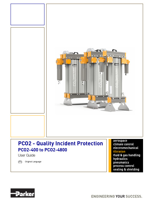
aerospaceclimate control electromechanical filtrationfluid & gas handling hydraulics pneumatics process control sealing & shielding1Safety Information (1)1.1Markings and Symbols (1)2Description (2)2.1Stages of Purification (2)2.2Technical Specification (2)2.2.1Pressure Correction Factors (2)2.3Weights and Dimensions (3)2.4Receiving and Inspecting the Equipment (4)2.4.1Storage (4)2.4.2Unpacking (4)2.4.3Overview of the Equipment (5)3Installation & Commissioning (6)3.1Recommended system layout (6)3.2Locating the Equipment (7)3.2.1Space Requirements (7)3.3Mechanical Installation (7)3.3.1General Requirements (7)3.3.2Securing the Unit (7)4Operating the Equipment (8)4.1Starting the Equipment (8)5Servicing (9)5.1Cleaning (9)5.2Service Intervals (9)5.3Preventative Maintenance Kits (10)5.4Maintenance Procedures (11)5.4.1Cartridge Replacement Procedure (PCO2-400 Models Only) (11)5.4.2OIL-X Element Change Procedure (13)5.4.3Cartridge Replacement Procedure (PCO2-800 to PCO2-4800 Models) (14)5.4.4IP50 Element Change Procedure (16)6Troubleshooting (17)1 Safety InformationDo not operate this equipment until the safety information and instructions in this user guide have been read and understood by all personnel concerned.USER RESPONSIBILITYFAILURE OR IMPROPER SELECTION OR IMPROPER USE OF THE PRODUCTS DESCRIBED HEREIN OR RELATED ITEMS CAN CAUSE DEATH, PERSONAL INJURY AND PROPERTY DAMAGE.This document and other information from Parker Hannifin Corporation, its subsidiaries and authorised distributors provide product or system options for further investigation by users having technical expertise.The user, through its own analysis and testing, is solely responsible for making the final selection of the system and components and assuring that all performance, endurance, maintenance, safety and warning requirements of the application are met. The user must analyse all aspects of the application, follow applicable industry standards, and follow the information concerning the product in the current product catalogue and in any other materials provided from Parker or its subsidiaries or authorised distributors.To the extent that Parker or its subsidiaries or authorised distributors provide component or system options based upon data or specifications provided by the user, the user is responsible for determining that such data and specifications are suitable and sufficient for all applications and reasonably foreseeable uses of the components or systems.Only competent personnel trained, qualified, and approved by Parker Hannifin should perform installation, commissioning, service and repair procedures.With the exception of oxygen, any gas can cause asphyxiation in high enough concentrations. Always ensure that the unit is operated in a well ventilated area and all of the vent ports on the rear of the unit are kept clear and free from blockages.Use of the equipment in a manner not specified within this user guide may result in an unplanned release of pressure, which may cause serious personal injury or damage.When handling, installing or operating this equipment, personnel must employ safe engineering practices and observe all related regulations, health & safety procedures, and legal requirements for safety.Ensure that the equipment is depressurised prior to carrying out any of the scheduled maintenance instructions specified within this user guide. Parker Hannifin can not anticipate every possible circumstance which may represent a potential hazard. The warnings in this manual cover the most known potential hazards, but by definition can not be all-inclusive. If the user employs an operating procedure, item of equipment or a method of working which is not specifically recommended by Parker Hannifin the user must ensure that the equipment will not be damaged or become hazardous to persons or property.Most accidents that occur during the operation and maintenance of machinery are the result of failure to observe basic safety rules and procedures. Accidents can be avoided by recognising that any machinery is potentially hazardous.Should you require an extended warranty, tailored service contracts or training on this equipment, or any other equipment within the Parker Hannifin range, please contact your local Parker Hannifin office.Details of your nearest Parker Hannifin sales office can be found at /gsfeRetain this user guide for future reference.Related Documents:• Preventative Maintenance Guide 176070002• 12 Month Service Instructions 1760700031.1 Markings and SymbolsThe following markings and international symbols are used on the equipment or within this manual:2 DescriptionThe Parker domnick hunter PCO2 systems offer a comprehensive solution to preserve and guarantee the quality of gaseous carbon dioxide used in sparkling beverage bottling.Operating as a Quality Incident Protection system against potential carbon dioxide impurities, the system guarantees the gas quality so itremains within industry and company guidelines, preventing detrimental consequences to the finished end beverage, producers reputation and their bottom-line.PCO2 is the beverage industry preferred choice and is installed in over 150 countries worldwide.2.1 Stages of Purification* Optional - Sterilising Grade: consult Parker for operational use.2.2 Technical SpecificationThis specification is valid when the equipment is located, installed, operated, and maintained as specified within this user guide.Stated flow rates are at 24.1 bar g (350 psi g).*Systems are installed in duplex / parallel to double the flow rate.All systems are supplied as NPT with stainless steel adapters 'NPT to BSP' as standard.PCO2 CO 2 systems are for gaseous CO 2 only.For flows at other pressures, apply the correction factors shown below.2.2.1 Pressure Correction FactorsStage 10.01 micron particle filtrationRemoval of non-volatile organic residue (NVOR) and other contaminants down to 0.01 ppmStage 2Removal of water vapour and partial removal of hydrocarbonsStage 3Primary removal of aromatic hydrocarbons (Benzene, Toulene etc and Acetaldehyde)Stage 4Removal of sulphur compounds (COS, H2S, DMS etc)Stage 50.01 micron particle filtrationStage 6*Point of use VBACE sterile gas membrane. Hi Flow Tetpor II ParameterUnitsPCO2400PCO2800PCO21600PCO22400PCO23200PCO24000PCO24800PCO23200(Duplex)*PCO24000(Duplex)*PCO24800(Duplex)*Technical DataMinimum Operating Pressure bar g (psi g) 3.0(43.5) 3.0(43.5) 3.0(43.5) 3.0(43.5) 3.0(43.5) 3.0(43.5) 3.0(43.5) 3.0(43.5) 3.0(43.5) 3.0(43.5)Maximum Operating Pressure bar g (psi g)20.7(300)24.1(350)24.1(350)24.1(350)24.1(350)24.1(350)24.1(350)24.1(350)24.1(350)24.1(350)Minimum Operating Temperature ºC (ºF)-20(-4)-20(-4)-20(-4)-20(-4)-20(-4)-20(-4)-20(-4)-20(-4)-20(-4)-20(-4)Maximum Operating Temperature ºC (ºF)40(104)40(104)40(104)40(104)40(104)40(104)40(104)40(104)40(104)40(104)Inlet CO 2 Quality ISBT beverage grade CO 2FlowrateKg / hr 1813637261089145118142177290336284354Lb / hr40080016002400320040004800640080009600Port Connections CO 2 Inlet in 1” NPT 1-1/2" NPT CO 2 Outletin1” NPT1-1/2" NPTInlet Pressurebar g 345678*********psi g44587387102116130145160174189Correction Factor 0.190.230.280.330.380.420.470.520.570.610.66Inlet Pressurebar g 1415161718192021222324psi g203218232247261275290304319333350Correction Factor0.710.760.800.850.900.95111112.3 Weights and Dimensions*Clearance required for the removal and servicing of the cartridges.Model Height (H)Width (W)Depth (D)(a)(b)(c)Clearance*Weight mm ins mm ins mm ins mm ins mm ins mm ins mm ins kg Ibs PCO2-400103540.7556422.2035013.78189.57.534013.430011.8168026.875165PCO2-800106141.7763224.8845017.72215.58.534013.440015.7568026.884185PCO2-1600106141.7780131.5445017.72215.58.550920.0440015.7568026.8128282PCO2-2400106141.7797038.1945017.72215.58.567826.7040015.7568026.8172379PCO2-3200106141.77113944.8445017.72215.58.584733.3540015.7568026.8217478PCO2-4000106141.77130851.5045017.72215.58.5101640.040015.7568026.8260573PCO2-4800106141.77147758.1545017.72215.58.5118546.740015.7568026.8304670(b)(b)PCO2-400PCO2-800 to PCO2-48002.4 Receiving and Inspecting the EquipmentOn receipt of the equipment carefully inspect the packaging for damage. If the packaging is damaged inform the delivery company immediately and contact your local Parker Hannifin office.2.4.1 StorageIf the equipment is to be stored prior to installation, do not remove it from the packaging. Ensure that it is stored in an upright position as indicated by the arrows on the packaging.Do not attempt to lift the equipment by yourself. It is recommended that the equipment be carried by a minimum of two persons ortransported on a pallet truck.Note. The storage area should be secure and the environmental conditions should fall within those specified in the technical specification.If the equipment is stored in an area where the environmental conditions fall outside of those specified, it is essential that it be moved to its final location (installation site) and left to stabilise prior to unpacking. Failure to do this could cause condensing humidity and potential failure of the equipment.2.4.2 UnpackingRemove the lid and all four sides of the packing crate. Carefully move the unit to its final location using a forklift truck or pallet truck. Once in it’s final location, remove the unit from the pallet via the 4x bolts.Note: Suitable slings and an overhead crane maybe required depending on the product size.2.4.3 Overview of the EquipmentKey:Item Description1System Inlet2System Outlet3AA020P OIL-X Filter (PCO2-400 Models only) IP50-AA-0465GPCO2 Filter4Manual Filter Drain5Manifold Lifting Handle6Manifold Hinge (PCO2-800 to PCO2-4800 Models) 7Desiccant Cartridge8PCO2 Column9Pressure Gauge10Lifting Eye Bolt7 8PCO2-400PCO2-800 to PCO2-4800 73 Installation & Commissioning3.1 Recommended system layoutOnly competent personnel trained, qualified, and approved by Parker Hannifin should perform commissioning and service procedures.1Liquid CO2 storage tank 2Vaporiser3Stainless steel piping4Pre filtration - Stage One 5PCO2 Unit6Post filtration - Stage five 7Isolation valves8Sterile Filter (Optional)54678 2313.2 Locating the Equipment3.2.1 Space RequirementsThe equipment should be mounted on a flat surface capable of supporting its own weight plus the weight of all ancillary parts. The minimum footprint requirements are specified below, however there must be adequate space around the equipment to allow airflow and access for maintenance purposes and lifting equipment. A minimum spacing of approximately 500mm (20 ins) is recommended around all sides of the unit and 750mm (30 ins) above it.Do Not position the equipment so that it is difficult to operate.3.3 Mechanical Installation3.3.1 General RequirementsEnsure that all piping materials are suitably rated for the application, clean and debris free. The diameter of the pipes must be sufficient to allow unrestricted inlet air supply to the equipment.Apply approximately 8 - 12 turns of P .T.F.E tape to the high quality stainless steel piping.Fit the piping along with the relevant pre and post filtration onto the inlet and outlet. Isolation valves must be installed before the inlet filtration and after the outlet filtration.When routing pipes ensure that they are adequately supported to prevent damage or leaks in the system.All components used within the system must be rated to at least the maximum operating pressure of the equipment. It is recommended that the system is protected with suitably rated pressure relief valves.3.3.2 Securing the UnitMounting holes are provided in the feet of the unit. Once the unit has been positioned in its final location ensure that it is securely fixed in place.500mm (20ins)(20ins)500mm(20ins)4 Operating the Equipment4.1 Starting the EquipmentNote: On start-Up it is normal for the outlet temperature to increase for a limited period of time.1 Open the inlet valve slowly to gradually pressurise the PCO2 unit.2 Open the outlet valve slowly to re-pressurise the downstream piping.Do not open the inlet or outlet valves rapidly or subject the PCO2 unit to excessive pressure differential as damage may occur.5 Servicing5.1 CleaningClean the equipment with a damp cloth only. If required you may use a mild detergent, however do not use abrasives or solvents as they may damage the warning labels on the equipment.5.2 Service IntervalsParker recommend that the adsorbent cartridges and filter elements are exchanged within the recommended 12-month period or before the recorded cumulative mass of the unit has been exceeded or after a quality incident has occurred, whichever comes first. Please refer to the below table for the maximum mass flow of each model.Service12 M o n t h s24 M o n t h s36 M o n t h s48 M o n t h s60 M o n t h s72 M o n t h sAPCO2 Model Number Max Operating Pressure Bar/PSI Flow kg/hr @ Max OperatingPressureMax Mass over 12 Months:kgFlow lb/hr@ Max OperatingPressureMax Mass over 12 Months:IbMax Mass over 12 Months: Tonne (Metric Ton)PCO2-40020 Barg / 300 PSIG 181158121640034944001581PCO2-80024 Barg / 350 PSIG 363317116880069888003170PCO2-160024 Barg / 350 PSIG 72663423361600139776006340PCO2-240024 Barg / 350 PSIG 108995135042400209664009510PCO2-320024 Barg / 350 PSIG 14511267593632002795520012680PCO2-400024 Barg / 350 PSIG 18141584710440003494400015850PCO2-480024 Barg / 350 PSIG 21771901827248004193280019020PCO2-3200 (Duplex)24 Barg / 350 PSIG 29032536060864005591040025361PCO2-4000 (Duplex)24 Barg / 350 PSIG 36283169420880006988800031701PCO2-4800 (Duplex)24 Barg / 350 PSIG435438036544960083865600380415.3 Preventative Maintenance KitsRequired every 8000Hrs (12 months)PCO2-400PCO2-800 to PCO2-4800AAAModelPM Kit NumberKit ContentsOrder QuantityPCO2 400MK-PCO2-4001x Desiccant cartridges 2x Outlet block o-rings 2x P020AA Filter element 2x Filter bowl o-rings 1PCO2 800MK-PCO2-8002x Desiccant cartridges 2x Outlet block o-rings 2x IP50-AA Filter element 2x Filter bowl o-rings 1PCO2 1600MK-PCO2-16004x Desiccant cartridges 2x Outlet block o-rings 2x IP50-AA Filter element 2x Filter bowl o-rings 1PCO2 2400MK-PCO2-24006x Desiccant cartridges 2x Outlet block o-rings 2x IP50-AA Filter element 2x Filter bowl o-rings 1PCO2 3200MK-PCO2-32008x Desiccant cartridges 2x Outlet block o-rings 2x IP50-AA Filter element 2x Filter bowl o-rings 1PCO2 4000MK-PCO2-400010x Desiccant cartridges 2x Outlet block o-rings 2x IP50-AA Filter element 2x Filter bowl o-rings 1PCO2 4800MK-PCO2-480012x Desiccant cartridges 2x Outlet block o-rings 2x IP50-AA Filter element 2x Filter bowl o-rings 1PCO2 3200 (Duplex)MK-PCO2-640016x Desiccant cartridges 4x Outlet block o-rings 4x IP50-AA Filter element 4x Filter bowl o-rings 1PCO2 4000 (Duplex)MK-PCO2-800020x Desiccant cartridges 4x Outlet block o-rings 4x IP50-AA Filter element 4x Filter bowl o-rings 1PCO2 4800 (Duplex)MK-PCO2-960024x Desiccant cartridges 4x Outlet block o-rings 4x IP50-AA Filter element 4x Filter bowl o-rings1With OIL-X IP50 filter elements (PCO2-800 to PCO2-4800)With OIL-X filter elements (PCO2-400 Models only)5.4 Maintenance Procedures5.4.1 Cartridge Replacement Procedure (PCO2-400 Models Only)Ensure that the system is fully depressurised before carrying out the below maintenance procedures.A Remove the M12 nuts from one side of the manifold.B Using the handle, carefully lift and remove the manifold from the unit and store in a safe place.Ensure that the inlet and outlet piping is adequately supported before removing the manifold from the unit.C Remove the old desiccant cartridges and dispose in accordance with local regulations.D Remove the o-ring from the outlet manifold block and replace with the one provided within the 12 month Preventative Maintenance kits.Note: Apply a light coating of Molykote III grease to the o-rings.E Insert the replacement desiccant cartridges into the columns.F Refit the manifold and secure the M12 nuts in sequence, starting with the centre nuts and working outwards. The nuts should be secured intwo stages. Stage 1: 27Nm (20 ft.lb) and Stage 2: 40Nm (30 ft.lb).A5.4.2 OIL-X Element Change ProcedureA Ensure that the filters are fully depressurised by opening the manual drain.B Unscrew the filter bowl and remove the used element.C Replace the o-ring located on the filter bowl with the new one provided within the 12month Preventative Maintenance kits.D Insert the new element into the filter bowl ensuring that the lugs are correctly seated inthe grooves.E Refit the filter bowl to the head ensuring that the threads are fully engaged and thelocking details are aligned.F Close the manual drain and re-pressurise the system.We recommend the use of gloves when touching contaminated elements.Ensure to lubricate the o-ring and threads with Molykote III grease.Item Description Item Description1Filter head4Filter bowl o-ring2Filter bowl5Manual Drain3Element5.4.3 Cartridge Replacement Procedure (PCO2-800 to PCO2-4800 Models)The top manifold has been split into two sections in order to simplify the removal of the desiccant cartridges.Ensure that the system is fully depressurised before carrying out the below maintenance procedures.A Remove the M12 nuts from one side of the manifold.B Using the handles, carefully lift the manifold until the M8 hex bolt has travelled to the top of the manifold hinge. Gently pull the manifoldtowards yourself until it has locked into position.C Carefully rotate the manifold 180o as shown. Once opened, place an M10 locking bolt through the holes in the two halves of the hinges toprevent the manifold falling onto the operator during service.Take care not to trap fingers/hands on the handles when rotating the manifold.D Remove the old desiccant cartridges and dispose in accordance with local regulations.Note: The cartridges should only be lifted using the handles and directly upwards to prevent clashing with the hinged manifold.E Remove the o-ring from the outlet manifold block and replace with the one provided within the 12 month Preventative Maintenance kits.Note: Apply a light coating of Molykote III grease to the o-rings.F Insert the replacement desiccant cartridges into the columns.Refit the manifold and secure the M12 nuts in sequence, starting with the centre nuts and working outwards. The nuts should be secured in two stages. Stage 1: 27Nm (20 ft.lb) and Stage 2: 40Nm (30 ft.lb).Replace the desiccant cartridges on the opposite side following the same procedure as above.5.4.4 IP50 Element Change ProcedureA Ensure that the filters are fully depressurised by opening the 1/4” BSPT ball valves.B Unscrew the filter bowl and then the used element from the tie rod.C Replace the o-ring located on the filter bowl with the new one provided within the 12month Preventative Maintenance kits.D Fit the new element onto the tie rod and tighten.E Refit the filter bowl to the head ensuring that the threads are fully engaged.F Close the 1/4” BSPT ball valves and re-pressurise the system.We recommend the use of gloves when touching contaminated elements.Ensure to lubricate the o-ring and threads with Molykote III grease.Item Description Item Description1Filter head4Element2Filter bowl5Filter bowl o-ring3Tie rod61/4” BSPT ball valve6 TroubleshootingProblem Indication Possible Cause Action RequiredPoor dewpoint Condensed water downstream ofthe system Bulk water carried over into thePCO2 unitCheck pre-filtration elements anddrainsOverflow of the PCO2 unitCompare flow through the PCO2unit to rated flowCheck for modifications to thecompressed air systemInlet pressure too low Check functioning of thecompressorInlet temperature too highCheck functioning of thecompressorCheck ventilation around the dryer Contaminated desiccantLocate and eliminate source ofcontamination and replace thedesiccantHigh pressure drop through filter / system package Pressure gauges fitted tocompressor / trainBlocked filters Replace any blocked filtersOverflow of the PCO2 unit Eliminate conditions leading toover flowOutlet air flow stops Indicated downstream pressuredrops to zero Compressor failure Investigate problem with the compressor and correctEU /-EC Type-examination Certificate:COV0912556/1Notified body for PED:Notified Body for ATEX:----B + DPED Assessment Route:29 April 2019Steven RohanDate:Signature:Parker Hannifin Manufacturing Limited GSFEDeclaration Number:00308Authorised Representative29.4.19--Lloyd's Register Verification 71 Fenchurch Street,London, EC3M 4BS-Standards used----Parker Hannifin Manufacturing Limited GSFEDukesway,Team Valley Trading Estate,Gateshead, Tyne & Wear,NE11 0PZ, UK PCO2 Carbon Dioxide Quality Incident Protection SystemGenerally in accordance with ASME VIII Div 1:2017and AS1210:2010PED----ENDeclaration of Conformity-Division Engineering Manager,This declaration of conformity issued under the sole responsibility of the manufacturer.DeclarationDirectives2014/68/EU -------PEDPCO2-400, PCO2-800, PCO2-1600, PCO2-2400, PCO2-3200, PCO2-4000, PCO2-4800Parker Hannifin Manufacturing Limited Gas Separation and Filtration Division EMEA Dukesway, Team Valley Trading Est Gateshead, Tyne and Wear England NE11 0PZTel: +44 (0) 191 402 9000Fax: +44 (0) 191 482 /gsfe© Parker Hannifin Corporation. All rights reserved.Catalogue: 176********/20 Rev: AEurope, Mi dd le East, AfricaAE – Unite d Arab Emirates, DubaiTel: +971 4 8127100********************AT – Austria, Wiener Neustadt Tel: +43 (0)2622 23501-0*************************AT – Eastern Europe, Wiener NeustadtTel: +43 (0)2622 23501 900****************************AZ – Azerbaijan, Baku Tel: +994 50 2233 458****************************BE/LU – Bel g ium, Nivelles Tel: +32 (0)67 280 900*************************BY – Belarus, Minsk Tel: +375 17 209 9399*************************CH – Switzerlan d , Etoy Tel: +41 (0)21 821 87 00*****************************CZ – Czech Republic, Klecany Tel: +420 284 083 111*******************************DE – Germany, Kaarst Tel: +49 (0)2131 4016 0*************************DK – Denmark, Ballerup Tel: +45 43 56 04 00*************************ES – Spain, Madrid Tel: +34 902 330 001***********************FI – Finlan d , Vantaa Tel: +358 (0)20 753 2500parker.fi ****************FR – France, Contamine s/Arve Tel: +33 (0)4 50 25 80 25************************GR – Greece, Athens Tel: +30 210 933 6450************************HU – Hun g ary, Budapest Tel: +36 1 220 4155*************************IE – Irelan d , Dublin Tel: +353 (0)1 466 6370*************************IT – Italy, Corsico (MI)Tel: +39 02 45 19 21***********************KZ – Kazakhstan, Almaty Tel: +7 7272 505 800****************************NL – The Netherlan d s, Oldenzaal Tel: +31 (0)541 585 000********************NO – Norway, Asker Tel: +47 66 75 34 00************************PL – Polan d , Warsaw Tel: +48 (0)22 573 24 00************************PT – Portu g al, Leca da Palmeira Tel: +351 22 999 7360**************************RO – Romania, Bucharest Tel: +40 21 252 1382*************************RU – Russia, Moscow Tel: +7 495 645-2156************************SE – Swe d en, Spånga Tel: +46 (0)8 59 79 50 00************************SK – Slovakia, Banská Bystrica Tel: +421 484 162 252**************************SL – Slovenia, Novo Mesto Tel: +386 7 337 6650**************************TR – Turkey, Istanbul Tel: +90 216 4997081************************UA – Ukraine, Kiev Tel +380 44 494 2731*************************UK – Unite d Kin gd om, Warwick Tel: +44 (0)1926 317 878********************ZA – South Africa, Kempton Park Tel: +27 (0)11 961 0700*****************************North AmericaCA – Cana d a, Milton, Ontario Tel: +1 905 693 3000US – USA, Cleveland Tel: +1 216 896 3000Asia Pacifi cAU – Australia, Castle Hill Tel: +61 (0)2-9634 7777CN – China, Shanghai Tel: +86 21 2899 5000HK – Hon g Kon g Tel: +852 2428 8008IN – In d ia, MumbaiTel: +91 22 6513 7081-85JP – Japan, Tokyo Tel: +81 (0)3 6408 3901KR – South Korea, Seoul Tel: +82 2 559 0400MY – Malaysia, Shah Alam Tel: +60 3 7849 0800NZ – New Zealan d , Mt Wellington Tel: +64 9 574 1744SG – Sin g apore Tel: +65 6887 6300TH – Thailan d , Bangkok Tel: +662 186 7000-99TW – Taiwan, Taipei Tel: +886 2 2298 8987South AmericaAR – Ar g entina, Buenos Aires Tel: +54 3327 44 4129BR – Brazil, Sao Jose dos Campos Tel: +55 800 727 5374 CL – Chile, Santiago Tel: +56 2 623 1216MX – Mexico, Apodaca Tel: +52 81 8156 6000Parker WorldwideEuropean Pro d uct Information Centre Free phone: 00 800 27 27 5374(from AT, BE, CH, CZ, DE, DK, EE, ES, FI, FR, IE, IL, IS, IT, LU, MT, NL, NO, PL, PT, RU, SE, SK, UK, ZA)。
世界十大油封品牌您知道几个?

三、台湾 WKF 密封件:
臺灣 WKF 密封創立於 20 世紀 80 年代,是專業的油封、密封件制造商,對於各種油封、密封件制品上我們擁有獨立開 發設計與制模的能力。 全廠產品均采用 ISO9001 及 TS16949 之品保系統,品質嚴格監控,使之皆能符合 ASTM、DIN、BS、JIS、SAE 等國際標 準,我們始終秉承品質第壹、客護至上、用心服務的經營理念。持續對我們的產品制程、研發以及服務質量進行改進, 提高產品的市場競爭力。同時以客護至上、用心服務的態度來解抉客護的密封系統問題,獲得客護的信任,創造雙贏 的未來。 公司成立以來,我們不斷把誠信和客護利益放在優先位置,不斷加強服務與管理來提升公司的信譽。 我們也可以依您的圖面客至您要的產品,如果您對密封件有任何的問題,請隨時與我們聯系。 台湾 WKF 油封产品型号: TC 型双唇口外包胶骨架油封、SC 型单唇口外包胶骨架油封、TB 型双唇口外铁壳油封、SB 型单唇口外铁壳油封、TA 型 双唇口加强型外铁壳油封、SA 型单唇口加强型外铁壳油封、VC 型无弹簧骨架油封、VB 型油封、EC/CAP 型端盖油封、 VA 型水封、VS 型水封、TCV 型耐压油封、TCN 型耐高压油封、DKB 型铁壳防尘油封、GA 型铁壳防尘油封、DC 型双面油
七、美国 Garlock 密封密封件:
Garlock 是一家着重于安全性、产品寿命和生产效率的高性能流体密封件及管道解决方案跨国制造商。我们与客户、行业协会和政 府机构合作,了解他们独特的密封挑战并采取创新的解决方案,以便在提高盈利能力的同时确保人员的安全。 他们的解决方案为以下行业提供业界领先的密封完整性和性能: 化工、工程、采购和建设、食品和饮料、海事、采矿、核能、石油与天然气、制药、发电、原生金属、纸浆和造纸、水和废水、 OEM Garlock 的历史可以追溯到 125 年前,目前在全球范围内拥有制造和分销机构,从而使他们可以快速满足客户的需求。 他们还运营着最先进的研究、开发和测试机构,以继续推进密封行业的现状,从而满足工业客户快速变化的需求。 通过将最具创新性的产品与无与伦比的服务和强烈的环保承诺相结合,他们提供可提高工厂生产率、降低成本并符合日益严格的环 保法规的解决方案。
Parker 多路阀-工程机械
F1与F2的做功相等
V = A1S1 = A2S2 W1 = F1S1 = pA1S1 W2 = F2S2 = pA2S2 W1 = W 2
9
液压传动 基础知识
c:流体的能量守恒 - 柏努利 (Bernoulli) 方程
10
液压技术的基础理论
3.几个概念
a) 压力 - 单位面积上所受的作用力
定量泵或变量泵 复制负载信号 紧急停止 流量共享 单独的压力补偿器 供给减压阀 力控制(力反馈功能) 响应快, 无泄漏油口溢流阀 阀芯执行器范围广 阀芯功能广 背压阀 内置式先导压力控制油源 可选装多功能阀块
44
选项功能举例
进口片中的旁通功能, 用于定量泵供油的系统 泵卸载功能起作用时切断泵进口, 这样使系统包括了急停功能 特定片的压力补偿 特定片的负载保持单向阀 特定片的溢流和防气穴功能 特定片的供给减压 特定油口的力反馈功能, 能实现力传感也提供液压斜坡功能 负载信号复制功能消除微下沉 在出口片中的内置先导压力功能 背压功能,提供非常好的补油特性和卸载下落的可能性 特定的双速功能, 能够实现像起重机和高空作业车这类机器的性能与精度之间的 切换 自动停止功能,用于选定的机器运动发生过载或者碰上其他的预先设定的限位 手柄脱离功能, 当远程控制起作用时, 它使直动式操作杆不起作用 机器的优先功能, 如制动和转向
5
液压传动的优缺点
缺点
噪声; 外部泄漏,会造成环境污染,即使是少量的矿物油漏泄, 也会毁坏大片的地表水;不过现在已越来越普遍地使用可 生物降解的液压油液; 易受污染,液压工作介质中的污染物质会导致介质变质、 元件磨损、系统性能恶化; 对环境温度较敏感,温度过高或过低均会影响甚至破坏元 件的可靠性和系统的性能。 液压油液中的气体会破坏系统的刚性,引起气穴,导致液 压泵和其它液压元件的损坏。
斜轴式轴向柱塞定量液压泵 马达 F11 F12 系列说明书
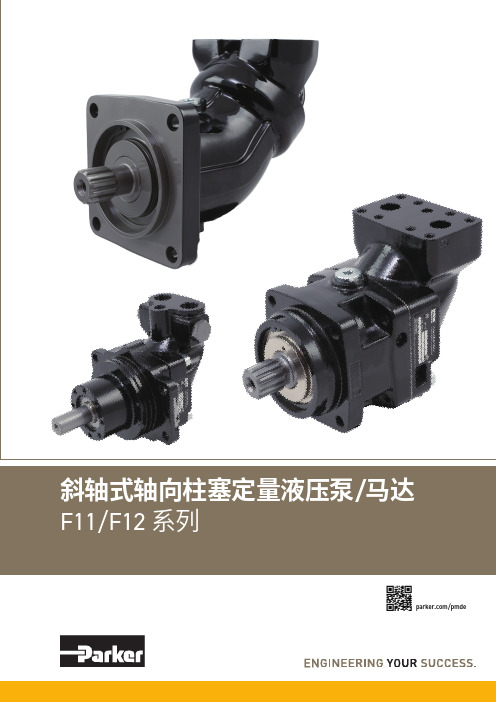
/马达/pmde2Parker HannifinPump & Motor Division Europe Trollhättan, Sweden液压泵/马达F11/F12 系列样本 MSG30-8249/CN换算系数1 kg ..............................................................................2.20 lb 1 N .............................................................................0.225 lbf 1 Nm .....................................................................0.738 lbf ft 1 bar ..........................................................................14.5 psi 1 l .................................................................0.264 US gallon 1 cm 3 ...................................................................0.061 cu in 1 mm ..........................................................................0.039 in 1°C ..........................................................................5/9(°F-32)1 kW ............................................................................1.34 hp换算系数1 lb ............................................................................0.454 kg 1 lbf .............................................................................4.448 N 1 lbf ft .....................................................................1.356 Nm 1 psi ..................................................................0.068948 bar 1 US gallon .................................................................3.785 l 1 cu in .................................................................16.387 cm 31 in ............................................................................25.4 mm 1°F .........................................................................9/5°C + 321 hp ........................................................................0.7457 kW扭矩 (M)M =[Nm]液压马达基本公式流量 (q)q = [l/min]功率 (P) P = [kW]D x n1000 x ηv D x Δp x ηhm63q x Δp x ηt600D - 排量 [cm 3/rev] n - 轴转速 [rpm] ηv - 容积效率Δp - 进油口和出油口之间的压差 [bar] ηhm - 机械效率 ηt - 总效率(ηt = ηv x ηhm )扭矩 (M)M = [Nm]液压泵基本公式流量 (q)q = [l/min]功率 (P)P = [kW]D x n x ηv1000 D x Δp63 x ηhmq x Δp600 x ηtD - 排量 [cm 3/rev] n - 轴转速 [rpm] ηv - 容积效率Δp - 进油口和出油口之间的压差 [bar] ηhm - 机械效率 ηt - 总效率(ηt = ηv x ηhm )销售条件本样本中的各种产品均由派克汉尼汾公司及其子公司和授权经销商销售。
Parker Push-Lok 801 804 821 836 管筒与附配件说明说明书
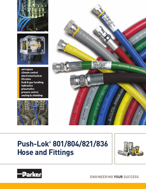
Hose and FittingsParker Push-Lok® – The Most Complete Line of Premium-Quality, Low-Pressure Hose and FittingsParker’s Push-Lok Plusmultipurpose hose line featuresthe widest fluid compatibility,application range and size range inthe industry. It also incorporatesthe highest working pressure in allsizes, making it the most versatilegeneral-purpose hose available.Easy Assembly andOrganizationThe Push-Lok system is easy touse. No clamps or special toolsare required during installation.And with Parker’s exclusive color-code system, you can inventory,maintain and identify your hoseneeds easily and efficiently.Exceptional Value and SavingsParker Push-Lok assembliescan be made in seconds, savingvaluable time and cost.And, Push-Lok 82 Series fittingsare reusable. You can replace thehose at the job site without anyspecial tools or clamps.Operational IntegrityHelping you maintain a cleanwork environment is anotherimportant reason to use Parker’sPush-Lok system. Its unique sealensures reliable, durable,leak-free service.Outstanding quality, valuableefficiency and Parker’s leak-freeassurance are what you get withevery Parker Push-Lok hose andfitting system. The industry’s mostcomplete line of low-pressurehose and fittings, Push-Lok offersthe range and versatility to meetall your needs.The “Push-Lok” BenefitsPush-Lok Plus 801 hose providesthe quick and easy assembly/disassembly advantage and thefullest range of color-codingto benefit your operations.It’s now approved with both 82Series push-on and HY Seriescrimp fittings.Push-Lok Plus 804 hose featuresquick and easy assembly andprovides an EPDM inner-tubefor hot water, dry air andphosphate- ester fluids.Push-Lok 821 is a higherpressure multipurpose hosethat is widely used for shop airsystems and general industrialand maintenance applications.It’s approved with 82 Seriesfittings, and is also available witha fire resistant (FR) cover for usenear welding operations.Push-Lok Plus 836 delivershigh temperature up to 302°F,heat-resistant performance andhigher working pressures than821, along with the same HY and82 Series fittings compatibility.Fiber braid reinforcement layer High-quality elastomer cover —The Color-Coded AdvantagesImproved Inventory ControlAssign a Push-Lok color to each department for its maintenance requirements. The color system helps assure that hoses are routed to their correct areas, resulting in better control over hose inventories.Identifying Industrial Drop LinesUse Push-Lok colors to identify drop line length and diameter for faster and easier replacement. When replacing by color, the right size and length are automatically set.Easier, Faster Line IdentificationIn applications where a number of hose lines carry different media, Push-Lok colors reduce timely “tracing” of lines, preventing disconnection of the wrong line and unnecessary, costly downtime.More Efficient Preventive MaintenanceUsing color-coded Push-Lok hose is an excellent way to keep track of scheduled replacement of low-pressure hose in youroperations. Just assign a different color hose to each replacement period and eliminate the possibility of missing lines scheduled for replacement.Enhanced Product AppearanceFor equipment manufacturers and their customers, using Push-Lok color hoses can vastly improve the visual and functional appeal of work equipment, on-line systems and the overall facility.*For pressure values in bars, multiply the Mpa value times 10. For pressure values in kPa, multiply the Mpa value times 1000. For pressure values in kgf/cm 2, multiply the Mpa value times 10,2.801PartWorkingMinimumField NumberHose I.D. Hose O.D. Pressure Bend Radius Weight Parkrimp Attachableinch mminch mmpsi MPainch mmlbs/ft kg/mHY Series82 SeriesColor CodesGRA RED YEL BLU GRN BLKColor CodesBLKColor CodesBLK801-4 1/4 6,3 0.50 12,7 350 2,4 2-1/2 65 0.09 0,13 • •801-6 3/8 10 0.63 15,9 350 2,4 3 75 0.11 0,16 • •801-8 1/2 12,5 0.78 19,8 300 2,1 5 125 0.18 0,27 • •801-10 5/8 16 0.91 23,0 300 2,1 6 150 0.19 0,28 • •801-12 3/4 19 1.03 26,2 300 2,1 7 180 0.24 0,36 • •801-161251.2832,62001,4102500.370,55••836PartWorkingMinimumFieldNumberHose I.D. Hose O.D. Pressure Bend Radius Weight Parkrimp Attachableinch mminch mmpsi MPainch mmlbs/ft kg/mHY Series82 SeriesColor CodesBLU836-4 1/4 6,3 0.50 12,7 400 2,8 2-1/2 65 0.09 0,13 • •836-6 3/8 10 0.63 15,9 400 2,8 3 75 0.11 0,16 • •836-8 1/2 12,5 0.78 19,8 400 2,8 4 125 0.18 0,27 • •836-10 5/8 16 0.91 23,0 350 2,4 5 150 0.19 0,28 • •836-123/4191.0326,23002,161800.240,36••804PartWorkingMinimumVacuum Rating FieldNumberHose I.D. Hose O.D. Pressure Bend Radius WeightAttachableinch mminch mmpsi MPainch mmlbs/ft kg/m 82 Series804-4 1/4 6,3 0.50 12,7 150 1,7 2-1/2 65 0.09 0,13 15 51 •804-6 3/8 10 0.63 15,9 150 1,7 3 75 0.11 0,16 15 51 •804-8 1/2 12,5 0.78 19,8 100 1,7 5 130 0.18 0,27 15 51 •804-10 5/8 16 0.91 23,0 100 1,0 6 150 0.19 0,28 15 51 •804-123/4191.0326,21001,771800.240,3615 51•Hgof HG kPa inches 821PartWorkingMinimumVacuum Rating FieldNumberHose I.D. Hose O.D. Pressure Bend Radius WeightAttachableinch mminch mmpsi MPainch mmlbs/ft kg/m 82 Series821-4 1/4 6,3 0.50 12,7 350 2,4 2-1/2 64 0.06 0,09 28 95 •821-6 3/8 10 0.63 15,9 300 2,1 3 76 0.09 0,13 28 95 •821-8 1/2 12,5 0.78 19,8 300 2,1 5 127 0.12 0,18 28 95 •821-10 5/8 16 0.91 23,0 250 1,7 6 152 0.19 0,28 28 95 •821-123/4191.0326,22501,771780.210,3128 95•Hgof HG kPa inchesPartWorkingMinimumVacuum Rating FieldNumberHose I.D. Hose O.D. Pressure Bend Radius WeightAttachableinch mminch mmpsi MPainch mmlbs/ft kg/m 82 Series821FR-4 1/4 6,3 0.50 12,7 350 2,4 2-1/2 64 0.08 0,12 28 95 •821FR-6 3/8 10 0.63 15,9 300 2,1 3 76 0.11 0,16 28 95 •821FR-8 1/2 12,5 0.78 19,8 300 2,1 5 127 0.12 0,18 28 95 •821FR-123/4191.0326,22501,771780.220,3328 95•821FRColor CodesWHT BRN BLU GRN BLKHgof HG kPa inchesAssembly and Disassembly Steps Assembly is easy1.Cut hose cleanly and squarelywith a sharp knife or a ParkerPush-Lok cut-off tool2. Lubricate the Push-Lok fittingand/or Hose I.D. with a light oilor soapy water only. Do notuse heavy oil or grease.3.Insert fitting into hose untilthe barb is in the hose.4.Place end fitting against aflat object (bench or wall).Grip hose approximately oneinch from end and push withsteady force until the end ofthe hose bottoms on the fittingand is covered by the yellowplastic cap.Disassembles fast1.Leave fitting in place andcut hose lengthwise fromthe yellow cap approximatelyone inch. IMPORTANT: Becareful not to nick barbswhen cutting hose.2.Grip hose and give a sharpdownward tug to disengagethe fitting.Caution: Push-Lok fittings will properly grip Push-Lok hose only when pushed all the wayin with the cut end of the hose completely concealed by the yellow plastic cap.Sealing integrity may be damagedby using exterior clamps.4 poundsField Attachable**367823J9823B2823C4823J7823C5823698233982379823378234182For use with Parkrimp style crimpers.179HY139HY141HY193HY10LHY11LHY1J9HY1J1HY 169HYParker Fluid Connectors GroupNorth American Divisions & Distribution Service CentersYour complete source for quality tube fittings, hose& hose fittings, brass & composite fittings, quick-disconnect couplings, valves and assembly tools, locally available from a worldwide network of authorized distributors.Fittings:Available in inch and metric sizes covering SAE, BSP, DIN, GAZ, JIS and ISO thread configurations, manufactured from steel, stainless steel, brass, aluminum, nylon and thermoplastic.Hose, Tubing and Bundles: Available in a wide variety of sizes and materials including rubber, wire-reinforced, thermoplastic, hybrid and custom compounds. Worldwide Availability: Parker operates Fluid Connectors manufacturing locations and sales offices throughout North America, South America, Europe and Asia-Pacific.For information, call toll free... 1-800-C-PARKER(1-800-272-7537)North American DivisionsEnergy Products DivisionStafford, TXphone 281 566 4500fax 281 530 5353Fluid System ConnectorsDivisionOtsego, MIphone 269 694 9411fax 269 694 4614Hose Products DivisionWickliffe, OHphone 440 943 5700fax 440 943 3129Industrial Hose DivisionStrongsville, OHphone 440 268 2120fax 440 268 2230Parflex DivisionRavenna, OHphone 330 296 2871fax 330 296 8433Quick Coupling DivisionMinneapolis, MNphone 763 544 7781fax 763 544 3418Tube Fittings DivisionColumbus, OHphone 614 279 7070fax 614 279 7685Distribution Service CentersBuena Park, CAphone 714 522 8840fax 714 994 1183Conyers, GAphone 770 929 0330fax 770 929 0230Lakeville, MNphone 952 469 5000fax 952 469 5729Louisville, KYphone 502 937 1322fax 502 937 4180Portland, ORphone 503 283 1020fax 503 283 2201Toledo, OHphone 419 878 7000fax 419 878 7001fax 419 878 7420(FCG Kit Operations)CanadaGrimsby, ONTphone 905 945 2274fax 905 945 3945(Contact Grimsby for otherService Center locations.)Push-Lok is a registered trademark of Parker Hannifin Corp.© 2011 Parker Hannifin CorporationParker Hannifin CorporationFluid Connectors GroupHose Products Division30240 Lakeland BoulevardWickliffe, OH 44092phone440 943 5700fax440 943 3129*************************4281-B1 5/2011。
parker接头、派克接头简介

parker 接头简介Parker 接头,是美国ParkerHannifin 公司德国工厂的德国工程师Ermto(埃米托)发明于上世纪30 年代,为了纪念其用其名字命名为parker接头,parker接头又名parker卡套式管接头。
Parker接头在中国------parker 接头特性:派克卡套式管接头因其特有的装配方便(仅需两把扳手)而广受欢迎。
经过近80多年的发展,EO工厂始派克接头图册(7张)终保持着卡套式管接头技术的领先地位。
今天,parker管接头是世界上使用最为广泛的一种管接头。
EO管接头是为公制管子设计的,历史上曾经依照德国标准DIN3861、DIN3859和DIN2353,现在这些标准已被国际标准ISO8434取代。
Parker管接头以体积小,压力等级高而著称。
分为低压、中压和高压三个系列(LL、L、S系列)这样使得各种不同的应用场合可以实现最经济化和空间最小化的方案。
parker 接头材质及规格Parker 管接头的材料除了最常见的碳钢镀锌以外,还提供铜和不锈钢两种材料,以适应不同的流体或环境条件。
Parker不锈钢接头的螺母螺纹采用镀银并预先润滑(规格15L-42L,12S-38S),较小规格的螺母螺纹采用蜡封,这样不仅有效的消除了不锈钢螺纹的咬合现象,同时减少40%装配拧紧力矩。
Parker管接头具有50多种不同的形式,可供各种不同应用场合的灵活选择,加上许多parker功能管接头,如旋转接头、球阀、单向阀、截止阀、测压接头等与parker 管接头配合使用,可大大方便系统的配套,提高系统密封的可靠性。
PARKER 液压软管具有防腐、耐高温、抗拉强度高,柔韧性好等诸多性能,而被广泛采用在各行业的液压工程中,派克软管有一层至多层钢丝编织增强层(6层以上),有低、中、高、超高三种压力等级,有轻、重两系列,公称通径在3 — 32mm。
有普通型和特殊型两种软管以满足在普通环境及特殊环境下使用,先进的不剥胶软管极大减轻装配劳动强度,广泛应用在各行业液压系统管路中。
各种型号液压产品介绍

目前宁波北仑卓玛液压机械有限公司可成熟替换的产品如下:德国力士乐REXROTH MCR系列液压马达、GFT系列减速机等法国波克兰POCLAIN MS系列柱塞液压马达及车轮式马达斯达弗STAFFA HMB、HMC系列五星液压马达戴纳密克DINAMIC 卷扬机(液压绞车)、减速机丹佛斯DANFOS OMP\OMR\OMS\OMV\OMT等等摆线式液压马达意大利SAI GM系列低速大扭矩液压马达DENISON CALZONI(丹尼逊、卡桑尼) MR、MRE等系列低速大扭矩液压马达(五星马达) PARKER(派克)、WHITE(怀特)、EA TON(伊顿) TG、TE、2K、6K等摆线式液压马达日本川崎Kawasaki重工 SX、HMKB、HMKC等系列液压马达(五星马达)意大利罗西ROSSI减速机 RCE系列等直角轴式减速机意大利布雷维尼(Brevini) 行星减速机、液压绞车等邦飞利(bonfiglioli) 行星减速机等波克兰乳化液马达 SP,HSP乳化液马达/宁波北仑卓玛液压机械有限公司是专业生产低速大扭矩液压马达及减速机、液压绞车的制造商。
主要产品有:QJM系列球塞式液压马达,NHM系列五星液压马达,BM系列摆线式液压马达,GM系列摆缸式液压马达,提升液压绞车,牵引液压绞车,液压绞盘,液压回转(传动)装置,车轮式液压马达,行走马达,MS 柱塞式液压马达,履带底盘,承接全套液压系统的设计与制造。
且成熟替换国外知名品牌低速马达及减速机系列,产品技术成熟,供货时间快,价格实惠。
广泛应用于建筑工程机械,起重运输机械,冶金重型机械,石油勘探设备,煤矿机械,船舶设备,机床,地质勘探设备等各个行业领域。
液压马达可直接驱动履带行走,轨道轮子驱动,各种回转提升,勘探钻孔,带式输送,物料搅拌,路面切割,船舶起锚等等目前可成熟替换的产品如下:德国力士乐REXROTH MCR系列液压马达、GFT系列减速机等法国波克兰POCLAIN MS系列柱塞液压马达及车轮式马达斯达弗STAFFA HMB、HMC系列五星液压马达戴纳密克DINAMIC 卷扬机(液压绞车)、减速机丹佛斯DANFOS OMP\OMR\OMS\OMV\OMT等等摆线式液压马达意大利SAI GM系列低速大扭矩液压马达DENISON CALZONI(丹尼逊、卡桑尼) MR、MRE等系列低速大扭矩液压马达(五星马达) PARKER(派克)、WHITE(怀特)、EATON(伊顿) TG、TE、2K、6K等摆线式液压马达日本川崎Kawasaki重工SX、HMKB、HMKC等系列液压马达(五星马达) 意大利罗西ROSSI减速机RCE系列等直角轴式减速机意大利布雷维尼(Brevini) 行星减速机、液压绞车等邦飞利(bonfiglioli) 行星减速机等波兰乳化液马达SP,HSP乳化液马达主营:液压马达,行星减速机,液压绞车,液压回转装置,液压系统,行走马达摆线液压马达类:专业生产各种类型液压马达和替换进口马达丹佛斯DANFOSS,型号液压马达完全替换(OMP,OH,OMR,DS,OMH,OMEW)(OMS,OMT,OMV) 丹佛斯DANFOSS液压马达1.微型马达(OML,OMM),中型马达(OMP,OH,OMR,DS,OMH,OMEW),大型马达(OMS,OMT,OMV),40系列轴向柱塞马达 ,90系列轴向柱塞马达 ,L型和K型变量马达 ,TM系列轴向柱塞马达,DCM系列径向柱塞马达,轴向柱塞二位LV马达,51及51-1系列斜轴变量马达 ,径向柱塞马达(DCM系列),摆线马达,我们提供 1600 多种不同的液压马达,并按型号、外形及尺寸分类(包括不同规格的输出轴)进行分类。
PARKER派克B53424MTF气动电磁阀技术参数讲解说明

PARKER派克B53424MTF气动电磁阀技术参数讲解说明PARKER派克B53424MTF气动电磁阀技术参数讲解说明HYLIK海历克张涛张经理今天给大家讲讲关于PARKER派克B53424MTF气动电磁阀没有现货的额,需要订货的,订货周期8-10周左右的。
这款B53424MTF气控阀这个型号自带线圈的,客户不需要再单独购买线圈了哦。
下面带给大家是到货实物图以及技术参数讲解等。
“既然人生只是一场体验,那就少不了酸甜苦辣各尝一遍,悲欢离合都经历一次。
夏天,不是季节,是一种内心的状态。
冰激凌,不是冷饮,是一种恰逢其时的快乐。
锅碗瓢盆,不是厨具,是构成生活的一件件乐器。
人生是用来体验的,不是用来演绎美的。
接受自己身上那些灰暗的部分,原谅自己的迟钝和平庸,允许自己出错,允许自己偶尔断电。
无论怎样,不要气馁,更别放弃,请昂首阔步走下去。
唯有历经风雨的洗涤,方可与彩虹不期而遇。
”B系列,一种性能越的工业阀门,尺寸紧凑,流量范围增强。
有电磁先导操作和远程空气先导型号可供选择。
B系列采用Parker久经考验的WCS(磨损补偿密封)系统,保使用寿命长、响应快。
PARKER派克B53424MTF气动电磁阀适用于端环境Viking Xtreme系列阀是用于劣环境工业的管接式阀。
电磁先导控制&气控先导,可选择汇流板和震动线圈。
抗盐雾和抗冲击。
温度从40F到140F;工作压力从真空到232PSIG;接口螺纹尺寸从1/8"到1/2"。
-Viking Xtreme系列Viking Lite系列阀是用于通用工业的管接式阀。
是先导控制、汇流板安装式。
温度范围从14F到122F,工作压力从22到145PSI;接口螺纹尺寸从1/8" 到 3/8"。
派克B53424MTF技术规格:最高运行温度:122°F,59°c低运行温度:14°F,-10°c最大运行压力:10bar ,145 psig 阀门类型:3通,4通位置数量:2位,3位端口数量:5通启动类型:电磁先导控制超控功能:非锁定和锁定手动按钮安装类型:管接,IEM 汇流棒歧管出口数量:10端口尺寸:1/8 1/4 3/8 端口类型:BSPP,NPT最小流速:0.6Cv 最大流速:2.5Cv输入电压:24VDC,120VAC 电气连接:22mm:3针(DIN 43659 B型)符合规格:IP65,RoHs,CE 额定压力:22到145psig ,1.5到10bar最小运行压力:22,43.5 psig 工作温度:-10到+50°c,+14到+122°F介质:空气润滑剂:无需润滑功耗:2.5w 阀体材质:阳极氧化铝密封材质:丁晴橡胶Viking Lite阀是一种坚固的,多功能的管接式阀,结合了高性能和紧凑的安装尺寸,非常适合于一般通用的工业应用。