AVL使用手册_Flow_meter
AVL_PD_735S+753C_Fuel_Mass_Flow_Meter+Temp_Control_CN

AVL 产品描述燃油消耗测量AVL质量流量式油耗仪&燃油温度控制系统技术描述AVL质量流量式油耗仪和AVL燃油温度控制系统是一套高精度的燃油消耗连续测量和控制系统,它已经在世界上被广泛应用于各种台架和机型,最大测量能力达到125kg/h。
系统以高精度测量和稳定的温度控制闻名于世。
模块化的设计,配套的控制单元,使得本系统的测量精度令人称道。
AVL质量流量式油耗仪与AVL燃油温度控制设备组成的测量系统在低流速和短时间测量的情况下也能提供极高的测量精度。
系统由于采用高精度的质量流量传感器,可做到连续的质量流量kg/h测量。
因此无需对密度进行额外的测量。
在台架试验环境中,燃油消耗的测量精度可达0.12%。
在多油品版本中,还可测量100%的酒精及人造柴油。
功能综述•油耗显示为kg/h, l/h, l/h (API)•燃油密度显示为g/cm³•测量和显示真实油耗的频率最大为20Hz•可对预设的测量时间和测量重量内的燃油消耗进行平均值测量•平均值计算时偏离和不确定度与常规一样•温度控制设定---模拟量或RS232•真实温度显示---模拟量或RS232•在测量循环中连续评估温度梯度•报错功能以避免无效测量•气泡分离和监控•完全自动的检查和标定,标定单元(选项)•快速便捷的燃油替换•错误和状态信息显示•服务周期显示•冷却水供应的监控•自动燃油排气功能适用范围AVL质量流量式油耗仪和AVL温度控制设备是一套高精度,燃油消耗连续测量和控制系统,在低流速和短时间测量的情况下也能提供极高的测量精度。
您的受益•直接质量流量测量精度高达0.12%,稳定的温度控制•开放式的连续测量系统(测量循环中没有额外的压力增加,如由于温度变化…)•在低油耗的工况下测量反应时间也是极短•极高的测量可靠性和稳定性适合各种现代的喷射系统•一个传感器和测量单元可以覆盖从单缸机到600kw的大发动机•按照ISO9001制定的内置标定检查功能(选项:标定单元)技术内容完整的系统包括一个AVL质量流量式油耗仪和一个AVL燃油温度控制设备。
AVL_PD_735S+753C_Fuel_Mass_Flow_Meter+Temp_Control_CN
AVL 产品描述燃油消耗测量AVL质量流量式油耗仪&燃油温度控制系统技术描述AVL质量流量式油耗仪和AVL燃油温度控制系统是一套高精度的燃油消耗连续测量和控制系统,它已经在世界上被广泛应用于各种台架和机型,最大测量能力达到125kg/h。
系统以高精度测量和稳定的温度控制闻名于世。
模块化的设计,配套的控制单元,使得本系统的测量精度令人称道。
AVL质量流量式油耗仪与AVL燃油温度控制设备组成的测量系统在低流速和短时间测量的情况下也能提供极高的测量精度。
系统由于采用高精度的质量流量传感器,可做到连续的质量流量kg/h测量。
因此无需对密度进行额外的测量。
在台架试验环境中,燃油消耗的测量精度可达0.12%。
在多油品版本中,还可测量100%的酒精及人造柴油。
功能综述•油耗显示为kg/h, l/h, l/h (API)•燃油密度显示为g/cm³•测量和显示真实油耗的频率最大为20Hz•可对预设的测量时间和测量重量内的燃油消耗进行平均值测量•平均值计算时偏离和不确定度与常规一样•温度控制设定---模拟量或RS232•真实温度显示---模拟量或RS232•在测量循环中连续评估温度梯度•报错功能以避免无效测量•气泡分离和监控•完全自动的检查和标定,标定单元(选项)•快速便捷的燃油替换•错误和状态信息显示•服务周期显示•冷却水供应的监控•自动燃油排气功能适用范围AVL质量流量式油耗仪和AVL温度控制设备是一套高精度,燃油消耗连续测量和控制系统,在低流速和短时间测量的情况下也能提供极高的测量精度。
您的受益•直接质量流量测量精度高达0.12%,稳定的温度控制•开放式的连续测量系统(测量循环中没有额外的压力增加,如由于温度变化…)•在低油耗的工况下测量反应时间也是极短•极高的测量可靠性和稳定性适合各种现代的喷射系统•一个传感器和测量单元可以覆盖从单缸机到600kw的大发动机•按照ISO9001制定的内置标定检查功能(选项:标定单元)技术内容完整的系统包括一个AVL质量流量式油耗仪和一个AVL燃油温度控制设备。
AVL自动排放分析系统操作作业指导书

AVL自动排放分析系统操作作业指导书1 开机1.1 开启室内总电源开关。
1.2 开启CVS机柜开关。
1.3 开启AMA机柜开关。
1.4 开启计算机,双击桌面的AMA4000快捷方式,进入AMA4000。
1.5 开启气瓶,调整2级表的压力在0.2-0.3MPa左右。
1.6 等待系统热机,约半个小时之后,点击main function 中的standby,如果待机条件达到,则进入待机状态,否则会报警标明FID分析仪或者CLD分析仪温度没有达到。
2标定分析仪2.1 分析仪至少需要预热2小时。
2.2 进入AMA的第三级菜单,选定某一分析仪。
2.3 点击zero gas(零气),然后点击span gas(量距气),读取数值,如果和预期值相差范围在5%以内,可以点击adjust进行标定,标定过程中adjust背景颜色为蓝色,标定结束后,adjust的背景蓝色消失(除了CLD分析仪的零气为合成空气外,其他分析仪的零气都是氮气)。
2.4 然后选择其他分析仪,按照上述过程进行标定。
2.5 也可以进入AMA的二级菜单,点击zero gas,然后点击span gas,不过在二级菜单中,进行的操作是针对所有分析仪,进行adjust也是针对所有分析仪,建议用户在熟练操作之前不要在二级菜单内进行标定的操作。
2.6 摩托车安装好,底盘测功机进入“工况测试”画面。
3 开启MC-Compact,进行试验循环3.1 在开启MC-Compact之前,要注意保证三个条件,一个为系统处在standby (待机) 的状态,二是remote enable,最后一个是系统没有出现报警。
3.2 满足三个条件之后,点击桌面上的MC-Compact的快捷方式。
3.3 点击开始,系统启动DAS4000 (速度比较慢),选择相应的循环,1如:ECE_R40,这时可以选择在循环进行过程中想要出现的模式。
3.4 点击左下角的三角型的标志,开始循环。
3.5 进行气袋的排空和清洗,结束后,出现”Ready to go”,并且叉号变黑。
AVL教学
A VL使用说明1.什么是A VLA VL (Athena V ortex Lattice)是MIT的Mark Drela教授开发的一个气动分析程序。
程序最初由Harold Youngren 1988年为MIT Athena TODOR 航空软件集编写。
经过Mark Drela 和Harold Youngren大量修改后,现在已发展到3.15版了。
A VL 的气动分析部分用FORTRAN编写而成,图形显示则是基于XWindows,用C语言编写,正是因为基于这两种以速度著称的语言,A VL运算起来特别快。
而且它的的跨平台性也比较好,在UNIX和Windows系统下都能运行。
2.A VL能做什么A VL利用涡格法对给定的外形作气动分析,采用关键字描述几何外形,计算出数据并绘制图形,而且数据和图形都能够输出。
这在计算后利用其结果十分方便。
A VL具有为飞机外型快速分析的大量特性,主要的特征如下:气动分力升力面细长体外型描述关键字驱动的几何外型输入文件使用线形插值描述截面截面特性翼型可以是NACA xxxx, 或者来自于翼型输入文件操纵面偏转抛物线形剖面极线,尺度放缩对整个表面或机身做缩放、平移、旋转复制整个表面或机身特性马蹄涡(表面)源线+双合线(机身)有限主体选择离散化归一化正弦余弦组合操纵面偏转通过倾斜法向量前缘襟翼后缘襟翼铰轴线独立于离散过程普通自由流描述alpha, beta 气流角p,q,r 飞机旋转分力亚音速Prandtl-Glauert 可压缩流处理空气动力分力输出直接力和力矩特瑞夫兹平面(Trefftz-plane)力及力矩的导数,w.r.t自由流,旋转,控制力在体坐标或固定坐标下配平计算控制变量alpha, betap, q, r操纵面偏转约束对变量的直接约束通过指定升力系数、力矩来间接约束一次定义多个配平算例保存配平算例设置以备以后调用可选质量定义文件(仅在配平设置,模态分析中)用户选择单位逐条列出部件位置,质量和惯性约束下的配平设置平直或带斜坡的水平飞行固定速率的俯仰飞行模态分析准稳定模型下的刚体分析显示带参数的特征根级数实时显示模态运动输出动态系统矩阵3.涡格法模型使用的原则就如同其它数值算法一样,A VL的用处同样有所限制。
AVL用户手册
AVL 3.14 User Primerlast update 28 Aug 2004Mark Drela, MIT Aero & AstroHarold Youngren, Aerocraft, Inc.HistoryAVL (Athena Vortex Lattice) 1.0 was originally written by Harold Youngren circa 1988 for the MIT Athena TODOR aero software collection. A number of modifications have since been added by Mark Drela and Harold Youngren,to the point where only a trace of the original code remains.General DescriptionAVL 3.xx now has a large number of features intended for rapid aircraft configuration analysis. The major features are as follows:Aerodynamic componentsLifting surfacesSlender bodiesConfiguration descriptionKeyword-driven geometry input fileDefined sections with linear interpolationSection propertiescamberline is NACA xxxx, or from airfoil filecontrol deflectionsparabolic profile drag polar, Re-scalingScaling, translation, rotation of entire surface or bodyDuplication of entire surface or bodySingularitiesHorseshoe vortices (surfaces)Source+doublet lines (bodies)Finite-core optionDiscretizationUniformSineCosineBlendControl deflectionsVia normal-vector tiltingLeading edge flapsTrailing edge flapsHinge lines independent of discretizationGeneral freestream descriptionalpha,beta flow anglesp,q,r aircraft rotation componentsSubsonic Prandtl-Glauert compressibility treatmentDirect forces and momentsTrefftz-planeDerivatives of forces and moments, w.r.t freestream, rotation, controlsIn body or stability axesTrim calculationOperating variablesalpha,betap,q,rcontrol deflectionsConstraintsdirect constraints on variablesindirect constraints via specified CL, momentsMultiple trim run cases can be definedSaving of trim run case setups for later recallOptional mass definition file (only for trim setup, eigenmode analysis)User-chosen unitsItemized component location, mass, inertiasTrim setup of constraintslevel or banked horizontal flightsteady pitch rate (looping) flightEigenmode analysisRigid-body analysis with quasi-steady aero modelDisplay of eigenvalue root progression with a parameterDisplay of eigenmode motion in real timeOutput of dynamic system matricesVortex-Lattice Modeling PrinciplesLike any computational method, AVL has limitations on what it can do.These must be kept in mind in any given application.ConfigurationsA vortex-lattice model like AVL is best suited for aerodynamic configurationswhich consist mainly of thin lifting surfaces at small angles of attack and sideslip. These surfaces and their trailing wakes are represented as single-layer vortex sheets, discretized into horseshoe vortex filaments, whose trailing legs are assumed to be parallel to the x-axis. AVL provides the capability to also model slender bodies such as fuselages and nacelles via source+doublet filaments. The resulting force and moment predictions are consistent with slender-body theory, but the experience with this model is relatively limited, and hence modeling of bodies should be done with caution. If a fuselage is expected to have little influence on the aerodynamic loads, it's simplest to just leave it out of the AVL model.Unsteady flowAVL assumes quasi-steady flow, meaning that unsteady vorticity sheddingis neglected. More precisely, it assumes the limit of small reduced frequency, which means that any oscillatory motion (e.g. in pitch) must be slow enoughthe flow to traverse an airfoil chord. This is true for virtually any expected flight maneuver. Also, the roll, pitch, and yaw rates usedin the computations must be slow enough so that the resulting relativeflow angles are small. This can be judged by the dimensionlessrotation rate parameters, which should fall within the followingpractical limits.-0.10 < pb/2V < 0.10-0.03 < qc/2V < 0.03-0.25 < rb/2V < 0.25These represent extremely violent aircraft motion, and are unlikelyto exceeded in any typical flight situation, except possibly duringlow-airspeed aerobatic maneuvers. In any case, if any of theseparameters falls outside of these limits, the results should beinterpreted with caution.Compressibility---------------Compressibility is treated using the Prandtl-Glauert (PG) transformation.Its relative importance can be judged by the PG factor 1/B = 1/sqrt(1 - M^2), where "M" is the freestream Mach number. A few values are given in the table, which shows the expected range of validity.M 1/B--- -----0.0 1.000 |0.1 1.005 |0.2 1.021 |0.3 1.048 |- PG expected valid0.4 1.091 |0.5 1.155 |0.6 1.250 |0.7 1.400 PG suspect (transonic flow likely)0.8 1.667 PG unreliable (transonic flow certain)0.9 2.294 PG hopelessFor swept-wing configurations, the validity of the PG modelis best judged using the wing-perpendicular Mach numberMperp = M cos(sweep)Since Mperp < M, swept-wing cases can be modeled up to higherM values than unswept cases. For example, a 45 degree swept wingMperp = 0.8 * cos(45) = 0.566which is still within the expected range of PG validityin the above table. So reasonable results can be expectedfrom AVL for this case.When doing velocity parameter sweeps at the lowest Mach numbers,say below M = 0.2, it is best to simply hold M = 0. This willgreatly speed up the calculations, since changing the Mach numberrequires recomputation and re-factorization of the VL influence matrix,which consumes most of the computational effort. If the Mach numberis held fixed, this computation needs to be done only once.Input Files===========AVL works with three input files, all in plain text format. Ideallythese all have a common arbitrary prefix "xxx", and the following extensions:xxx.avl required main input file defining the configuration geometry xxx.mass optional file giving masses and inertias, and dimensional units xxx.run optional file defining the parameter for some number of run casesThe user provides files xxx.avl and xxx.mass, which are typically created using any text editor. Sample files are provided for use as templates.The xxx.run file is written by AVL itself with a user command.It can be manually edited, although this is not really necessarysince it is more convenient to edit the contents in AVL and thenwrite out the file again.Geometry Input File -- xxx.avl==============================This file describes the vortex lattice geometry and aerodynamicsection properties. Sample input files are in the /runs subdirectory.Coordinate system-----------------The geometry is described in the following Cartesian system:注意坐标系和机体坐标系相同Y out the right wingZ upThe free stream must be at a reasonably small angle to the X axis(alpha and beta must be small), since the trailing vorticityis oriented parallel to the X axis. The length unit used inthis file is referred to as "Lunit". This is arbitrary,but must be the same throughout this file.File format-----------Header data- - - - - -The input file begins with the following information in the first 5 non-blank, non-comment lines:Abc... | case title# | comment line begins with "#" or "!"0.0 | Mach1 0 0.0 | iYsym iZsym Zsym4.0 0.4 0.1 | Sref Cref Bref0.1 0.0 0.0 | Xref Yref Zref0.020 | CDp (optional)Mach = default freestream Mach number for Prandtl-Glauert correctioniYsym = 1 case is symmetric about Y=0 , (X-Z plane is a solid wall)= -1 case is antisymmetric about Y=0, (X-Z plane is at const. Cp)= 0 no Y-symmetry is assumed是否存在纵向对称iZsym = 1 case is symmetric about Z=Zsym , (X-Y plane is a solid wall) = -1 case is antisymmetric about Z=Zsym, (X-Y plane is at const. Cp) = 0 no Z-symmetry is assumed (Zsym ignored)好像可以考虑地效Sref = reference area used to define all coefficients (CL, CD, Cm, etc)Cref = reference chord used to define pitching moment (Cm)Bref = reference span used to define roll,yaw moments (Cl,Cn)X,Y,Zref = default location about which moments and rotation rates are defined (if doing trim平衡calculations, XYZref must be the CG location,which can be imposed with the MSET command described later)CDp = default profile drag coefficient added to geometry, applied at XYZref (assumed zero if this line is absent, for previous-version compatibility)The default Mach, XYZref, and CDp values are superseded取代by the valuesin the .run file (described later), if it is present. They can alsobe changed at runtime.Only the half (non-image) geometry must be input if symmetry is specified. Ground effect is simulated with iZsym = 1, and Zsym = location of ground.(该程序可以计算地效)Forces are not calculated on the image/anti-image映像surfaces.Sref and Bref are assumed to correspond to the total geometry.In practice there is little reason to run Y-symmetric image cases,unless one is desperate不顾一切的for CPU savings.Surface and Body data- - - - - - - - - - -The remainder of the file consists of a set of keywords and associated data. Each keyword expects a certain number of lines of data to immediately follow it, the exceptions being inline-coordinate keyword AIRFOIL which is followed by an arbitrary number of coordinate data lines. The keywords must also be nested嵌套的properly in the hierarchy层次shown below. Only the first four characters of each keyword are actually significant, the rest are just a mnemonic帮助记忆的.SURFACEINDEXYDUPLICATESCALETRANSLATEANGLESECTIONSECTIONNACASECTIONCLAFCDCLSECTIONAFILECONTROLCONTROLBODYYDUPLICATESCALETRANSLATEBFILESURFACEYDUPLICATESECTIONSECTIONSURFACE..etc.The INDEX, YDUPLICATE, SCALE, TRANSLATE, and ANGLE keywordscan all be used together. If more than one of these appears for a surface, the last one will be used and the previous ones ignored.At least two SECTION keywords must be used for each surface.The NACA, AIRFOIL, AFILE, keywords are alternatives.If more than one of these appears after a SECTION keyword,the last one will be used and the previous ones ignored. i.e.SECTIONNACAAFILEis equivalent toSECTIONAFILEMultiple CONTROL keywords can appear after a SECTION keyword and dataSurface-definition keywords and data formats- - - - - - - - - - - - - - - - - - - - - - -*****SURFACE | (keyword)Main Wing | surface name string12 1.0 20 -1.5 | Nchord Cspace [ Nspan Sspace ]The SURFACE keyword declares that a surface is being defined untilthe next SURFACE or BODY keyword, or the end of file is reached.A surface does not really have any significance to the underlyingAVL vortex lattice solver, which only recognizes the overallcollection of all the individual horseshoe vortices. SURFACEis provided only as a configuration-defining device, and alsoas a means of defining individual surface forces. This isnecessary for structural load calculations, for example.Nchord = number of chord wise horseshoe vortices placed on the surfaceCspace = chordwise vortex spacing parameter (described later)Nspan = number of spanwise horseshoe vortices placed on the surface [optional] Sspace = spanwise vortex spacing parameter (described later) [optional]If Nspan and Sspace are omitted (i.e. only Nchord and Cspace are present on line), then the Nspan and Sspace parameters will be expected for each section interval, as described later.*****INDEX | (keyword)3 | LsurfThis optional keyword allows declaring that multiple input SURFACEsactually constitute one physical surface, by giving them all thesame Lsurf value. This declaration is necessary for AVL to properlyperform calculations using finite core radii for the horseshoe vortices(the default case). A finite core radius is normally used for eachhorseshoe vortex, except when computing the influence of that vortexon a control point lying on the same physical surface. Using afinite core radius within the same surface would seriously corruptthe calculation.If each physical surface is specified via only a single SURFACE block,then the INDEX declaration is unnecessary.*****YDUPLICATE | (keyword)0.0 | YduplThe YDUPLICATE keyword is a convenient shorthand device for creating 。
AVL_PD_442_BlowByMeter_ENG_V02
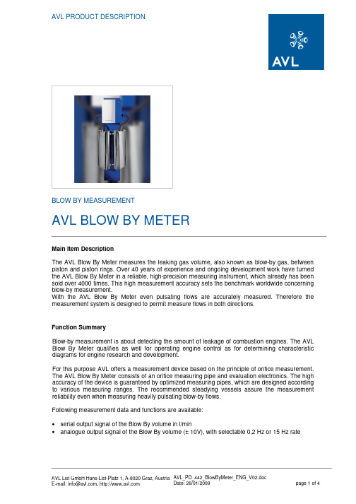
AVL PRODUCT DESCRIPTIONBLOW BY MEASUREMENTAVL BLOW BY METERMain Item DescriptionThe AVL Blow By Meter measures the leaking gas volume, also known as blow-by gas, between piston and piston rings. Over 40 years of experience and ongoing development work have turned the AVL Blow By Meter in a reliable, high-precision measuring instrument, which already has been sold over 4000 times. This high measurement accuracy sets the benchmark worldwide concerning blow-by measurement.With the AVL Blow By Meter even pulsating flows are accurately measured. Therefore the measurement system is designed to permit measure flows in both directions.Function SummaryBlow-by measurement is about detecting the amount of leakage of combustion engines. The AVL Blow By Meter qualifies as well for operating engine control as for determining characteristic diagrams for engine research and development.For this purpose AVL offers a measurement device based on the principle of orifice measurement. The AVL Blow By Meter consists of an orifice measuring pipe and evaluation electronics. The high accuracy of the device is guaranteed by optimized measuring pipes, which are designed according to various measuring ranges. The recommended steadying vessels assure the measurement reliability even when measuring heavily pulsating blow-by flows.Following measurement data and functions are available:•serial output signal of the Blow By volume in l/min•analogue output signal of the Blow By volume (± 10V), with selectable 0,2 Hz or 15 Hz rateApplicationApplications in engine research and development range from the optimization of the cylinder / piston pairing to the piston micrograph, the development of a favourable piston ring geometry to the design of positive crankcase ventilation systems. For monitoring continuous and running-in engine testing on quality test beds, the blow-by measurement is used as a manufacturing quality control check and for acceptance testing. One crucial task of the blow-by measurement is the monitoring of engines on all types of test beds.Benefits•low sensitivity to dirt•100 % availability of measurement data•reproducibility better than 0,1 %•accuracy of 1 % FS ( with fine calibration)•easy installation on test beds•correct measurement also with reverse flows•minimal pressure drop•simple detection of leaks ArrayView: Comparison of different measuring principlesTechnical InsightThe control and data evaluation unit is located in a cabinet (splash- proof, IP 55) which is directly connected with the orifice measuring pipe. The measurement pipe as well as the control and data evaluation unit are mounted on one console. The device can easily be connected by analogue or serial ( RS232C) ports to the test bed system, whereby the range of the blow-by amount is shown on the test bed computer or an alternative remote indication (optional).View: AVL Blow By Meter with two steadying vessels, installed on a mounting plateThe AVL Blow By Meter determines the flow rate using the orifice measurement principle.A differential pressure transducer measures the different gas pressures in front of and after the orifice and the volume of gas flowing through the orifice can be calculated from this difference.Following areas of measurement are available:measurement range : 0,2to 10 l/min 1,5to 75 l/min 3 to 150 l/min 6 to 300 l/min 12 to 600 l/min 24 to 1200 l/min 48 to 2400 l/minView: Different orificesOrifice principleTechnical DataMeasuring range : 0.2…2400 l/min (different orifice pipes)Accuracy: better than ± 1 % FS with optional fine linearizationbetter than ± 1,5 % FS standard linearizationOutlets: analogue ± 10 V matching ± 100 % FSRS232C conforming to AK generic communication protocol Power supply: 24 V DCPower consumption: 35 WProtection class: IP 55Temperature range: -10...55 °CDimension 3...150 l/min: approx. 330 x 350 x 75 mm (w x h x d)Scope of SupplyEach consisting of:1 Orifice measuring pipe1 Electronics2 Measurement tube clamps1 Power supply cable (24 V DC), length 15m1 Signal cable, length 15m1 Cable BBY RS232, length 15m1 Operating manual 442Options/ExtensionsThe AVL Blow By Meter can be expanded with following accessories:•different orifice measuring pipes•appropriate steadying vessels•orifice heating•different remote indications•absolute pressure sensor for the crank case•negative pressure application•AVL function tester。
AVL PUMA OPEN说明书

HEAVY DUTY ENGINE EMISSIONS With dynamic testbeds for the engines of utility vehicles, the focus is on strict compliance with the legislation despite the flexible use of advanced functions and additional measurement methods for engine development. AVL‘s packages guarantee the correct test procedure and display the results in a legally compliant and clear manner after the test has been completed.
specialized interfaces like ASAM-ODS and ASAM-CEA • Graphical formula editor for crank-angle- and time-based
calculations • Full programming environment for user-specific formulas,
LIGHT DUTY ENGINE EMISSIONS Increases in efficiency in the engine development process can be achieved by making use of the benefits of dynamic engine testbeds. It is essential in this area to comply with the basic conditions for exhaust gas measurements specified in the corresponding guidelines. AVL‘s packages contain suitable methods for different measurement equipment (e.g. undiluted raw exhaust gas measurement or diluted CVS measurement).
AVL设备说明综述DOC

新型摩托车发动机自动检测线(AVL 测功机台架系统AMA4000/CVS4000)技术资料功能:AVL 测功机台架系统是用于车辆台架试验, 如工况法排放认证试验和新产品的开发等的设备。
其包括:1.20”底盘测功机2.CVS4000-定容采样系统3.AMA4000-排气污染物分析仪(分别用于直接及稀释采样)4.GEM201L-自动控制系统原理:AVL 测功机台架系统是在底盘测功机上模拟真实的道路路面阻力, 用CVS系统(文氏里管原理)对车辆排放废气进行定容稀释并将废气在气袋中收集起来, 用排气污染物分析仪测量HC, NOX, CO, CO2的浓度, 用主控计算机控制试验的过程, 从底盘测功机, CVS系统, 排气污染物分析仪, 得到数据并计算出单位距离中有害废气的排放质量. 依据对排出废气的分析, 可在车辆上将化油器调到最佳状态。
CVS系统的关键部分, 文氏里管系统, 用于定容稀释取样.排放的测量是将车辆排出的废气与稀释空气进行混合, 保持通过文氏里管的流量恒定, 按一定比例取气并保存到气袋中, 试验循环结束后, 将气袋中的废气传输到分析单元中进行测量, 获得HC, NOX, CO, CO2的浓度. 排放和底盘测功机的有关参数送到主控计算机计算出车辆在单位里程中排放的污染物的质量。
下图为设备示意图:1.00.00 AMA 4000气体分析仪2台AMA 4000气体分析仪,分别用于直接及稀释采样(第二批发货)PIERBURG仪器公司AMA4000气体分析仪可以广泛的测量尾气排放中的气体成分,与发动机台架及底盘测功机台架同时使用。
AMA4000气体分析仪可以根据不同的应用要求,如法规认证试验或研究开发工作,提供不同配置的分析仪。
分析仪还可以提供扩展及选项,如全范围的分析仪,自动控制软件包及维护保养等,构成完整的产品系列。
AMA 4000气体分析仪,单采样管路用于汽油发动机及柴油发动机直接采样AMA 4000排放分析仪,单采样管路,用于汽油发动机及柴油发动机,具有以下功能:直采汽油车及柴油车排气的连续测量满足现在 EPA及 ECE法规要求分析仪部分:所有分析仪通过本地CAN-bus总线与中央分析仪控制单元 (ACU)通讯。
- 1、下载文档前请自行甄别文档内容的完整性,平台不提供额外的编辑、内容补充、找答案等附加服务。
- 2、"仅部分预览"的文档,不可在线预览部分如存在完整性等问题,可反馈申请退款(可完整预览的文档不适用该条件!)。
- 3、如文档侵犯您的权益,请联系客服反馈,我们会尽快为您处理(人工客服工作时间:9:00-18:30)。
Technical Information TI047D/06/en 50096459ElectromagneticFlow Measuring System PROline promag 50/53 PFlow rate measurement inchemical or process applicationsFeatures and benefits•Nominal diameters DN 15...600•PFA or PTFE lining•PFA for high temperature applications up to +180°C•Fitting lengths to DVGW and ISO •High accuracy:–Promag 50: ± 0.5% (option: ±0.2%)–Promag 53: ± 0.2%•Robust field housing, IP 67•IP 67 wall-mount housing for straight-forward installation of the remote ver-sion•Promag 53 with Touch Control:Operation without opening the housing − also for Ex-rated applications •Additionalsoftware packages:–pulsating flow–for batching applications –with the electrode cleaning•Interfaces for integration into all major process-control systems:–HART interface as standard –Promag 50: PROFIBUS-PA–Promag 53: PROFIBUS-PA/-DP , FOUNDATION Fieldbus•“Quick Setup” menus for straightfor-ward commissioning in the field•Ex approval for installation in Zone 1 (ATEX, FM, CSA, etc.)ApplicationAll fluids with a minimum conductivity of ≥5 µS/cm can be measured:•acids and caustic solutions •paints, lacquers •pastes, mashes•water, wastewater etc.A minimum conductivity of ≥20 µS/cm is required for measuring demineralized water.Liner specific applications:•PTFE lining for standard applications in chemical and process industries.•PFA lining for all applications in chemi-cal and process industries; especially for high process temperatures andapplications with temperature shocks.PROline Promag 50/53 PFunction and system designMeasuring principle Faraday’s law of induction states that a voltage is induced in a conductor moving in a magneticfield.In electromagnetic measuring, the flowing medium corresponds to the moving conductor. Theinduced voltage is proportional to the flow velocity and is detected by two measuring electrodesand transmitted to the amplifier. Flow volume is computed on the basis of the pipe's diameter. Theconstant magnetic field is generated by a switched direct current of alternating polarity.Ue = B · L · vQ = A · vUe = induced voltageB = magnetic induction (magnetic field)L = electrode gapv = flow velocityQ = volume flowA = pipe cross-sectionI = current strengthMeasuring system The measuring system consists of a transmitter and a sensor.Two versions are available:•Compact version: transmitter and sensor form a single mechanical unit.•Remote version: transmitter and sensor are installed separately.Transmitter:•Promag 50 (user interface with push buttons for operation, two-line display)•Promag 53 (“Touch Control” without opening the housing, four-line display)Sensor:•Promag P (DN 15…600)2Endress+HauserPROline Promag 50/53 PInputMeasured variable Flow rate (proportional to induced voltage)Measuring range Typically v = 0.01...10 m/s with the specified measuring accuracyOperable flow range Over 1000 : 1Input signal Status input (auxiliary input):U = 3…30 V DC, R i = 5 kΩ,galvanically isolated.Configurable for: totalizer(s) reset, measured value suppression, error-message reset.Current input (for Promag 53 only):Active/passive selectable, galvanically isolated, full scale value selectable, resolution: 3 µA,temperature coefficient: typ. 0.005% o.r./°C (o.r. = of reading)active: 4...20 mA, R i≤ 150 Ω, U out = 24 V DC, short-circuit-proofpassive: 0/4...20 mA, R i≤ 150 Ω, U max = 30 V DCOutputOutput signal Promag 50Current output:active/passive selectable, galvanically isolated, time constant selectable (0.01...100 s),full scale value selectable, temperature coefficient: typ. 0.005% o.r./°C (o.r. = of reading),resolution: 0.5 µA•active: 0/4…20 mA, R L < 700 Ω (HART: R L≥ 250 Ω)•passive: 4…20 mA, operating voltage V S 18...30 V DC, R i≤ 150 ΩPulse/frequency output:passive, open collector, 30 V DC, 250 mA, galvanically isolated.•Frequency output: full scale frequency 2...1000 Hz (f max = 1250 Hz), on/off ratio 1:1, pulse widthmax. 10 s.•Pulse output: pulse value and pulse polarity selectable, max. pulse width configurable(0.5...2000 ms)PROFIBUS-PA interface:•PROFIBUS-PA in accordance with EN 50170 Volume 2, IEC 61158-2 (MBP),galvanically isolated•Current consumption: 11 mA•Permissible supply voltage: 9...32 V•FDE (Fault Disconnection Electronic): 0 mA•Data transmission rate, supported baudrate: 31.25 kBit/s•Signal encoding: Manchester II•Function blocks: 1x Analog Input, 1 x Totalizer•Output data: Volume flow, Totalizer•Input data: Positive zero return (ON/OFF), Control totalizer, Value for local display•Bus address adjustable via DIP-switches at the measuring deviceEndress+Hauser3PROline Promag 50/53 PPromag 53Current output:active/passive selectable, galvanically isolated, time constant selectable (0.01...100 s),full scale value selectable, temperature coefficient: typically 0.005% o.r./°C (o.r. = of reading),resolution: 0.5 µA•active: 0/4…20 mA, R L < 700 Ω (HART: R L≥ 250 Ω)•passive: 4…20 mA, operating voltage V S 18...30 V DC, R i≤ 150 ΩPulse/frequency output:active/passive selectable, galvanically isolated (Ex i version: only passive)•active: 24 V DC, 25 mA (max. 250 mA during 20 ms), R L > 100 Ω•passive: open collector, 30 V DC, 250 mA•Frequency output: full scale frequency 2...10000 Hz (f max = 12500 Hz), EEx-ia: 2...5000 Hz;on/off ratio 1:1; pulse width max. 10 s.•Pulse output: pulse value and pulse polarity adjustable, pulse width configurable(0.05...2000 ms)PROFIBUS-DP interface:•PROFIBUS-DP/-PA in accordance with EN 50170 Volume 2, IEC 61158-2(MBP),galvanically isolated•Data transmission rate, supported baudrat: 9.6 kBaud...12 MBaud•Automatic data transmission rate recognition•Signal encoding: NRZ-Code•Function blocks: 2 x Analog Input, 3 x Totalizer•Output data: Volume flow, Corrected volumen flow, Totalizer 1 (3)•Input data: Positive zero return (ON/OFF), Totalizer control, Value for local display•Bus address adjustable via DIP-switches at the measuring devicePROFIBUS-PA interface:•PROFIBUS-PA in accordance with EN 50170 Volume 2, IEC 61158-2 (MBP),galvanically isolated•Current consumption: 11 mA•Permissible supply voltage: 9...32 V•Data transmission rate, supported baudrate: 31.25 kBit/s•Error current FDE (Fault Disconnection Electronic): 0 mA•Signal encoding: Manchester II•Function blocks: 2 x Analog Input, 3 x Totalizer•Output data: Volume flow, Corrected volumen flow, Totalizer 1 (3)•Input data: Positive zero return (ON/OFF), Totalizer control, Value for local display•Bus address adjustable via DIP-switches at the measuring deviceFOUNDATION Fieldbus interface:•FOUNDATION Fieldbus H1, IEC 61158-2 (MBP), galvanically isolated•Current consumption: 12 mA•Permissible supply voltage: 9...32 V•Error current FDE (Fault Disconnection Electronic): 0 mA•Data transmission rate, supported baudrate: 31.25 kBit/s•Signal encoding: Manchester II•Function blocks: 5 x Analog Input, 1 x Discrete Output, 1 x PID•Output data: Volume flow, Corrected volumen flow, Totalizer 1 (3)•Input data: Positive zero return (ON/OFF), Reset totalizer•Link Master (LM) functionality is supported4Endress+HauserPROline Promag 50/53 PSignal on alarm•Current output→failure response selectable (e.g. in accord. with NAMUR Recom. NE 43)•Pulse/frequency output→ failure response selectable•Status output (Promag 50) → non-conductive by fault or power supply failure•Relay output (Promag 53)→ de-energized by fault or power supply failureLoad See “Output signal”Switching output Status output (Promag 50):Open collector, max. 30 V DC / 250 mA, galvanically isolated.Configurable for: error messages, Empty Pipe Detection (EPD), flow direction, limit values.Relay outputs (Promag 53):Normally closed (NC or break) or normally open (NO or make) contacts available(default: relay 1 = NO, relay 2 = NC)max. 30 V / 0.5 A AC; 60 V / 0.1 A DC, galvanically isolated.Configurable for: error messages, Empty Pipe Detection (EPD), flow direction, limit values,batching contacts.Low flow cutoff Switch points for low flow cutoff are selectableGalvanic isolation All circuits for inputs, outputs, and power supply are galvanically isolated from each other. Endress+Hauser5PROline Promag 50/53 P6Endress+HauserPower supplyElectrical connection Measuring unitConnecting the transmitter, cable cross-section: max. 2.5 mm 2Top: field housingBottom: wall-mount housing aCable for power supply: 85...260 V AC, 20...55 V AC, 16...62 V DC Terminal No. 1: L1 for AC, L+ for DC Terminal No. 2: N for AC, L- for DCb Signal cable: Terminals Nos. 20–27→Page 8c Ground terminal for protective conductor d Ground terminal for signal-cable shielde Service connector for connecting service interface FXA 193 (FieldCheck, ToF Tool-FieldTool Package)f Cover of the connection compartment gSecuring clampPROline Promag 50/53 PEndress+Hauser 7Electrical connection Measuring unit(bus communication)Connecting the transmitter, cable cross-section: max. 2.5 mm 2Top: field housingBottom: wall-mount housing aCable for power supply: 85...260 V AC, 20...55 V AC, 16...62 V DC Terminal No. 1: L1 for AC, L+ for DC Terminal No. 2: N for AC, L- for DC bFieldbus cable:Terminal No. 26: DP (B) / PA (+) / FF (+) (with reverse polarity protection)Terminal No. 27: DP (A) / PA (–) / FF (–) (with reverse polarity protection)DP (A) = RxD/TxD-N; DP (B) = RxD/TxD-P c Ground terminal for protective conductor d Ground terminal for Fieldbus cablee Service connector for connecting service interface FXA 193 (FieldCheck, ToF Tool-FieldTool Package)f Cover of the connection compartmentgCabel for external termination (only PROFIBUS):Terminal No. 24: +5 V Terminal No. 25: DGND hSecuring clampabgPROline Promag 50/53 P8Endress+HauserTerminal assignment, Promag 50Terminal assignment, Promag 53The inputs and outputs on the communication board can be either permanently assigned or var-iable, depending on the version ordered (see table). Replacements for modules which are defec-tive or which have to be replaced can be ordered as accessories.Terminal No. (inputs / outputs)Order variant 20 (+) / 21 (–)22 (+) / 23 (–)24 (+) / 25 (–)26 (+) / 27 (–) 50***-***********W −−−Current outputHART 50***-***********A −−Frequency output Current outputHART 50***-***********D Status inputStatus outputFrequency outputCurrent outputHART 50***-***********H –––PROFIBUS-PA 50***-***********S ––Frequency output Ex i, passive Current output Ex i active, HART 50***-***********T––Frequency output Ex i, passiveCurrent output Ex i passive, HARTGround connection, power supply →Page 6Terminal No. (inputs / outputs)Order variant20 (+) / 21 (–)22 (+) / 23 (–)24 (+) / 25 (–)26 (+) / 27 (–)Fixed communication boards (fixed assignment)53***-***********A −−Frequency output Current outputHART 53***-***********B Relay outputRelay outputFrequency outputCurrent outputHART 53***-***********F –––PROFIBUS-PAEx i 53***-***********G –––FOUNDATION Fieldbus, Ex i 53***-***********H –––PROFIBUS-PA 53***-***********J –––PROFIBUS-DP 53***-***********K −−−FOUNDATION Fieldbus 53***-***********S −−Frequency outputEx i Current output Ex i active, HART 53***-***********T−−Frequency outputEx iCurrent output Ex i passive, HARTFlexible communication boards 53***-***********C Relay output Relay output Frequency output Current outputHART 53***-***********D Status input Relay output Frequency output Current outputHART 53***-***********L Status input Relay output Relay output Current outputHART 53***-***********M Status input Frequency output Frequency output Current outputHART 53***-***********2Relay output Current output Frequency output Current outputHART 53***-***********4Current input Relay output Frequency output Current outputHART 53***-***********5Status inputCurrent inputFrequency outputCurrent outputHARTGround connection, power supply →Page 6PROline Promag 50/53 PEndress+Hauser9Electrical connection remote versionn.c. = isolated cable shields, not connectedCable entryPower supply and signal cables (inputs/outputs):•Cable entry M20 x 1.5 (8...12 mm)•Threads for cable entries, PG 13.5 (5...15 mm), 1/2" NPT, 1/2"Connecting cable for remote version:•Cable entry M20 x 1.5 (8...12 mm)•Threads for cable entries, PG 13.5 (5...15 mm), 1/2" NPT, 1/2"Cable specifications remote versionCoil cable:•2 x 0.75 mm 2 PVC cable with common, braided copper shield (Ø approx. 7 mm)•Conductor resistance: ≤ 37 Ω/km•Capacitance: core/core, shield grounded: ≤ 120 pF/m •Permanent operating temperature: –20…+80 °C •Cable cross-section: max. 2.5 mm 2Signal cable:•3 x 0.38 mm 2 PVC cable with common, braided copper shield (Ø approx. 7 mm) and individu-ally shielded cores•With Empty Pipe Detection (EPD): 4 x 0.38 mm 2 PVC cable with common, braided copper shield (Ø approx. 7 mm) and individually shielded cores.•Conductor resistance: ≤ 50 Ω/km •Capacitance: core/shield: ≤ 420 pF/m•Permanent operating temperature: –20…+80 °C •Cable cross-section: max. 2.5 mm 2a = signal cable,b = coil current cable (cross-section: max. 2.5 mm 2)1 = core,2 = core insulation,3 = core shield,4 = core jacket,5 = core strengthening,6 = cable shield,7 = outer jacketPROline Promag 50/53 POptionally, E+H also supplies reinforced connecting cables with an additional, metal strenghten-ing braid. We recommend such cables for the following cases:•Cables laid underground•Danger of rodent attack•Device used with ingress protection IP 68Operation in zones of severe electrical interference:The measuring device complies with the general safety requirements in accordance withEN61010, the EMC requirements of EN61326/A1, and NAMUR recommendation NE21.Caution!Grounding is by means of the ground terminals provided for the purpose inside the connectionhousing. Keep the stripped and twisted lengths of cable shield to the terminals as short aspossible.Supply voltage85…260 V AC, 45…65 Hz20…55 V AC, 45…65 Hz16…62 V DCPROFIBUS-PA and FOUNDATION FieldbusNon-Ex: 9...32 V DCEx i: 9...24 V DCEx d: 9...32 V DCPower consumption AC: <15 VA (including sensor)DC: <15 W (including sensor)Switch-on current:•max. 13.5 A (< 50 ms) at 24 V DC•max. 3 A (< 5 ms) at 260 V ACPower supply failure Lasting min. 1 power cycle:•EEPROM or T-DAT™ (Promag 53 only) retain the measuring system data in the event of a powersupply failure•S-DAT™ = exchangeable data storage chip which stores the data of the sensor (nominal diam-eter, serial number, calibration factor, zero point, etc.)Potential equalisation Standard casePerfect measurement is only ensured when the medium and the sensor have the same electricalpotential. Most Promag sensors have a standard installed reference electrode which guaranteesthe required connection. This usually means that additional potential matching measures areunnecessary.For installation in metal pipes, it is advisable to connect the ground terminal of the transmitterhousing to the piping. Also, observe company-internal grounding guidelines.Caution!For sensors without reference electrodes or without metal process terminals, carry out potentialmatching as per the instructions for special cases described below. These special measures areparticularly important when standard grounding practice cannot be ensured or extremely strongmatching currents are expected.10Endress+HauserMetal, ungrounded pipingIn order to prevent outside influences on measurement, it is advisable to use ground cables toconnect each sensor flange to its corresponding pipe flange and ground the flanges. Connect thetransmitter or sensor connection housing, as applicable, to ground potential by means of theground terminal provided for the purpose.Caution!Also, observe company-internal grounding guidelines.Note!The ground cable for flange-to-flange connections can be ordered separately as an accessoryfrom E+H.•DN ≤ 300: The ground cable is in direct connection with the conductive flange coating and issecured by the flange screws.•DN ≥ 350: The ground cable connects directly to the metal transport bracket.Endress+Hauser11Plastic pipes and isolating lined pipesNormally, potential is matched using the reference electrodes in the measuring tube. However, inexceptional cases it is possible that, due to the grounding plan of a system, large matching cur-rents flow over the reference electrodes. This can lead to destruction of the sensor, e.g. throughelectrochemical decomposition of the electrodes. In such cases, e.g. for fibre-glass or PVC pip-ing, it is recommended that you use additional ground disks for potential matching.When using ground disks, note the following points:•Ground disks (DN 15...300) can be ordered separately from E+H as an accessory.•Ground disks (incl. seals) increase the installation length. You can find the dimensions ofground disks on Page30.Caution!•Risk of damage from electrochemical corrosion. Note the electrochemical insulation rating, ifthe ground disks and measuring electrodes are made of different materials.•Also, observe company-internal grounding guidelines.Pipes with cathodic protectionIn such cases, install the measuring instrument without potential in the piping:•When installing the measuring device, make sure that there is an electrical connection betweenthe two piping runs (copper wire, 6 mm2).•Make sure that the installation materials do not establish a conductive connection to the meas-uring device and that the installation materials withstand the tightening torques applied whenthe threaded fasteners are tightened.•Also comply with the regulations applicable to potential-free installation.1 = isolation transformer,2 = electrically isolated12Endress+HauserPerformance characteristicsReference operating conditions To DIN 19200 and VDI/VDE 2641:•Medium temperature: +28 °C ± 2 K •Ambient temperature: +22 °C ± 2 K •Warm-up period: 30 minutes Installation:•Inlet run >10 x DN•Outlet run > 5 x DN•Sensor and transmitter grounded.•Sensor centered relative to the pipe.Maximum measured error Promag 50:Pulse output: ± 0.5% o.r. ± 1 mm/s (o.r. = of reading)Current output: plus typically ± 5 µAPromag 53:Pulse output: ± 0.2% o.r. ± 2 mm/s (o.r. = of reading)Current output: plus typically ± 5 µASupply voltage fluctuations have no effect within the specified range.Max. measured error in % of readingRepeatability max. ± 0.1% o.r. ± 0.5 mm/s (o.r. = of reading)Endress+Hauser13Operating conditionsInstallation conditionsInstallation instructions Mounting locationCorrect measuring is possible only if the pipe is full. Avoid the following locations:•Highest point of a pipeline. Risk of air accumulating.•Directly upstream of a free pipe outlet in a vertical pipe.Installation of pumpsDo not install the sensor on the intake side of a pump. This precaution is to avoid low pressureand the consequent risk of damage to the lining of the measuring tube. Information on the lining'sresistance to partial vacuum can be found on Page21.It might be necessary to install pulse dampers in systems incorporating reciprocating, diaphragmor peristaltic pumps. Information on the measuring system's resistance to vibration and shock canbe found on Page19.Partially filled pipesPartially filled pipes with gradients necessitate a drain-type configuration. The Empty Pipe Detec-tion (EPD) function offers additional protection by detecting empty or partially filled pipes.Caution!Risk of solids accumulating. Do not install the sensor at the lowest point in the drain. It is advisableto install a cleaning valve.14Endress+HauserVertical pipesInstall a siphon (b) or a vent valve (a) downstream of the sensor in vertical pipes longer than5meters. This precaution is to avoid low pressure and the consequent risk of damage to the liningof the measuring tube. These measures also prevent the system losing prime, which could causeair inclusions. Information on the lining's resistance to partial vacuum can be found on Page21.a = vent valve,b = siphonOrientationAn optimum orientation helps avoid gas and air accumulations and deposits in the measuringtube. Promag, nevertheless, supplies a range of options and accessories for correct measuringof problematic mediums:•Electrode Cleaning Circuitry (ECC) to remove electrically conductive deposits in the measuringtube, e.g. in accretive mediums.•Empty Pipe Detection (EPD) for recognition of partially filled measuring tubes, or for degassingmediums or for applications with fluctuating process pressure.Vertical orientation:This orientation is ideal for self-emptying piping systems and for use in conjunction with EmptyPipe Detection.Endress+Hauser15Horizontal orientation:The measuring electrode-plane should be horizontal. This prevents brief insulation of the two elec-trodes by entrained air bubbles.Caution!Empty Pipe Detection functions correctly only when the measuring device is installed horizontallyand the transmitter housing is facing upward. Otherwise there is no guarantee that Empty PipeDetection will respond if the measuring tube is only partially filled or empty.1 = EPD electrode (Empty Pipe Detection)2 = Measuring electrodes (signal detection)3 = Reference electrode (potential equalisation)VibrationsSecure the piping and the sensor if vibration is severe.Caution!It is advisable to install sensor and transmitter separately if vibration is excessively severe.Information on resistance to vibration and shock can be found on Page19.16Endress+HauserFoundations, supportsIf the nominal diameter is DN ≥ 350, mount the transmitter on a foundation of adequate load-bearing strength.Caution!Do not allow the casing to take the weight of the sensor. This would buckle the casing anddamage the internal magnetic coils.Inlet and outlet runs If possible, install the sensor well clear of fittings such as valves, T-pieces, elbows, etc. Compli-ance with the following requirements for the inlet and outlet runs is necessary in order to ensuremeasuring accuracy:•Inlet run ≥ 5 x DN•Outlet run ≥ 2 x DNEndress+Hauser17Adapters Suitable adapters to (E) DIN EN 545 (double-flange junction sections) can be used to install thesensor in larger-diameter pipes. The resultant increase in the rate of flow improves measuringaccuracy with very slow-moving fluids.The nomogram shown here can be used to calculate the pressure loss caused by reducers andexpanders. The nomogram applies only to fluids of viscosity similar to water:1.Calculate the ratio of the diameters d/D.2.From the nomogram read off the pressure loss as a function of flow velocity (downstream fromthe reduction) and the d/D ratio.Length of connecting cable Permissible cable length Lmax depends on the conductivity of the medium. A minimum conduc-tivity of 20µS/cm is required for measuring demineralized water.Gray shaded area = permissible range for medium conductivityLmax = length of connecting cable in [m]Medium conductivity in [µS/cm]In order to ensure measuring accuracy, moreover, comply with the following instructions wheninstalling the remote version:•Secure the cable run or route the cable in a conduit. Movement of the cable can falsify themeasuring signal, particularly if the conductivity of the medium is low.•Route the cable well clear of electrical machines and switching elements.•Ensure potential equalisation between sensor and transmitter, if necessary.18Endress+HauserEnvironmentAmbient temperature Standard: –20…+60 °C (sensor, transmitter)Optional: –40...+60 °C (transmitter)Note the following points:•Install the device at a shady location. Avoid direct sunlight, particularly in warm climatic regions.•If both fluid and ambient temperatures are high, install the transmitter at a remote location fromthe sensor (→ “Medium temperature”)•At ambient temperatures below –20 °C the readability of the display may be impaired. Storage temperature–10...+50 °C (preferably +20 °C)•The measuring device must be protected against direct sunlight during storage in order toavoid unacceptably high surface temperatures.•Choose a storage location where moisture does not collect in the measuring device. This willhelp prevent fungus and bacteria infestation which can damage the liner.•Do not remove the protective plates or caps on the process connections until the device isready to install. This is particularly important in the case of sensors with PTFE linings.Degree of protection•Standard: IP 67 (NEMA 4X) for transmitter and sensor•Optional: IP 68 (NEMA 6P) for Promag P sensor, remote versionShock and vibration resistance Acceleration up to 2 g by analogy with IEC 68-2-6 (high-temperature version: no data available)Electromagneticcompatibility (EMC)To EN 61326/A1 and NAMUR recommendation NE 21Endress+Hauser1920Endress+HauserProcess conditionsMedium temperature rangeThe permissible medium temperature depends on the measuring-tube lining:•−40…+130 °C for PTFE (DN 15…600), for restrictions →refer to diagrams •−20…+180 °C for PFA (DN 25…200), for restrictions →refer to diagrams Compact version (PFA and PTFE lining)T A = ambient temperature, T F = fluid temperature HT = high-temperature version, with insulationRemote version (PFA and PTFE lining)T A = ambient temperature, T F = fluid temperature HT = high-temperature version, with insulationConductivityMinimum conductivity:≥ 5 µS/cm for fluids generally≥ 20 µS/cm for demineralised waterNote that in the case of the remote version, the minimum conductivity is also influenced by the length of the connecting cable → see “Length of connecting cable”Medium pressure range (nominal pressure)EN 1092-1 (DIN 2501): PN 10 (DN 200…600) PN 16 (DN 65…600) PN 25 (DN 200…600) PN 40 (DN 15…150) ANSI B16.5:Class 150 (1/2…24") Class 300 (1/2…6") JIS B2238:10K (DN 50…300)20K (DN 15…300)AS2129:Table E (DN25, 50)Pressure tightness (liner)NominaldiameterMeasuring tubeliningResistance to partial vacuum of measuring tube liningLimit values for abs. pressure [mbar] at various fluid temperatures [mm][inch]25 °C80 °C100 °C130 °C150 °C180 °C 151/2"PTFE000100−−251"PTFE / PFA0 / 00 / 00 / 0100 / 0− / 0− / 0 32−PTFE / PFA0 / 00 / 00 / 0100 / 0− / 0− / 0 40 1 1/2"PTFE / PFA0 / 00 / 00 / 0100 / 0− / 0− / 0 502"PTFE / PFA0 / 00 / 00 / 0100 / 0− / 0− / 0 65−PTFE / PFA0 / 0*40 / 0130 / 0− / 0− / 0 803"PTFE / PFA0 / 0*40 / 0130 / 0− / 0− / 0 1004"PTFE / PFA0 / 0*135 / 0170 / 0− / 0− / 0 125−PTFE / PFA135 / 0*240 / 0385 / 0− / 0− / 0 1506"PTFE / PFA135 / 0*240 / 0385 / 0− / 0− / 0 2008"PTFE / PFA200 / 0*290 / 0410 / 0− / 0− / 0 25010"PTFE330*400530−−30012"PTFE400*500630−−35014"PTFE470*600730−−40016"PTFE540*670800−−45018"PTFENo vacuum is permissible!50020"PTFE60024"PTFE* No value can be specified.Endress+Hauser21。