VLMG31K1L2-GS08中文资料
常用控制电缆规格型号表及说明

KVV控制电缆规格型号表之巴公井开创作一、表格定义二、使用说明尺度:聚氯乙烯绝缘控制电缆尺度:产品尺度:GB9330.2-88《聚氯乙烯绝缘和护套控制电缆》,IEC60227(60502,60332); SABS。
本产品供交流额定电压450V/750V或直流电压1000V及以下配电装置中电器,仪表接线之用。
应用:控制电缆适合布线的电气控制设备和仪器,监测和控制回路,电气呵护和丈量电源分配单元服务条件的情况下,额定电压为450/750V AC。
铺设:聚氯乙烯绝缘电缆长期工作温度为70℃;交联聚乙烯绝缘电缆长期工作温度为90℃敷设电缆的温度不克不及低于0℃。
允许弯曲半径:非铠装电缆(R):R≥6D(D:电缆外径);铠装或铜胶带屏蔽电缆:R≥12D;屏蔽软电缆:R≥10D。
注释:具体电缆芯数系列为,2,3,5,7,8,10,12,14,16,19,24,27,30,37;R--连接用软电缆(电线),软结构;V--绝缘聚氯乙烯 V--聚氯乙烯绝缘 V--聚氯乙烯护套;B--平型(扁形) S--双绞型;A--镀锡或镀银;F--耐高温;P--编织屏蔽 P2--铜带屏蔽 P22--钢带铠装;Y--预制型、一般省略,或聚烯烃护套FD--产品类别代号,指分支电缆,将要公布的建设部尺度用FZ暗示,其实质相同;YJ--交联聚乙烯绝缘;V--聚氯乙烯绝缘或护套;ZR--阻燃型;NH--耐火型;WDZ--无卤低烟阻燃型;WDN--无卤低烟耐火型;例:RV --铜芯、氯乙烯绝缘,连接电缆(电线);AVR-- 镀锡、铜芯、聚乙烯绝缘、平型、连接软,电缆(电线);RVB-- 铜芯、聚氯乙烯平型连接电线;RVS --铜芯、聚氯乙烯绞型连接电线;RVV --铜芯、聚氯乙烯绝缘、聚氯乙烯护套、圆形连接软电缆ARVV-- 镀锡、铜芯、聚氯乙烯绝缘、聚氯乙烯护套、平形连接软电缆RVVB --铜芯、聚氯乙烯绝缘、聚氯乙烯护套、平形连接软电缆RV-105 --铜芯耐热105℃、聚氯乙烯绝缘、聚氯乙烯绝缘、连接软电缆AF-205AFS-250AFP-250 --镀银、聚氯乙氟塑料绝缘、耐高温-60℃~250℃、连接软电线三、经常使用电(线)缆类型线缆规格型号含义:BV--暗示单铜芯、聚氯乙烯普通绝缘电线,无护套线。
实力专业用品-实力专业用品-实力专业用品说明书

7
DIN Adaptors
DIN Adaptor for RGS SSRs
Installation Instructions
Ordering Key
RGS1DIN
DIN rail adaptor module for mounting the RGS series on DIN rail.
Suffix H8 added to SSR part no. refers to factory mounted DIN clip. Conditions apply. Please ask your Sales representative for further details.
Ordering Key
Ordering Key
RGN - TERMRES
RGN-TERMRES termination resistor to be fitted on the last RG..N on the NRG bus chain. Packing qty. 4 pc.
Specifications are subject to change without notice (30.07.2019)
3-pin socket to mate with RM1E..V.. 4-pin socket to mate with RA2A..C 4-pin socket to mate with RA2A..C
5-pin socket to mate with RA..S 4-pin socket to mate with RKD2..C 2-pin socket to mate with RK2..C
Material Thermal resistance
环保型三价白铬电镀工艺
三价白铬电镀添加剂哪家好?传统六价铬电镀工艺对人类健康和环境保护构成日趋严重的威胁。
相对于六价铬电镀工艺而言,三价铬电镀工艺的体系更复杂,对杂质的敏感性更高,对添加剂的质量要求也更高。
本公司从2006年起即开始着手三价铬电镀工艺的研发工作,2008年就开发出了第一代的三价铬电镀添加剂,是目前国内研发最早,工艺最先进、最成熟的三价铬电镀添加剂供应商。
➢Unimirror TV CⅡ镜牌三价白铬电镀工艺的设备要求镀槽:PP,PVC,或内衬PVC或玻璃钢的钢铁槽阳极:采用TV CⅡ专用阳极及钛钩温度控制:使用钛素材的电热笔、蛇形冷却管过滤:采用高密度炭芯连续过滤,二次循环每小时整流器:要求配置安培小时计,整流器容量不低于12V备注:阴、阳极导电排使用树脂包覆铜材料,并且最好配置自动添加器➢Unimirror TV CⅡ镜牌三价白铬电镀的工艺参数及操作条件原料及操作条件范围最佳值TV CⅡ-BC复合盐250-300克/升260克/升TV CⅡ-CC铬盐140-160克/升150克/升TV CⅡ-CAT稳定剂55-75 ml/L 60 ml/LTV CⅡ-MS 抑雾剂2-5 ml/L 3 ml/LTV CⅡ-EXT络合剂1-2 ml/L 1ml/LPH值 2.5-3.0 2.8温度30-40℃32℃比重24-26 26阴极电流密度8-16 ASD 13 ASD阳极电流密度 3.5-5.5 ASD 4.5 ASD阳极材料TVC三价铬专用阳极过滤连续过滤搅拌中等程度机械式或空气搅拌加热采用纯钛加热管加热镀层沉积速率0.10-0.125 microns / min➢Unimirror TV CⅡ镜牌三价白铬电镀工艺开缸方法1.洗净镀缸,注入60%体积的纯水,加热至60℃;2.开启空气搅拌,缓慢加入260克/升的TV CⅡ-BC 复合盐及150克/升TV CⅡ-CC铬盐,搅拌至完全溶解。
注意:加入TV CⅡ-BC复合盐后,镀液温度会急剧下降,必须维持加入以防温度下降导致溶解不彻底。
dk32 遥控器用户手册说明书

DK32遥控器用户手册非常感谢您购买我司产品。
DK32是一款优秀的无线电遥控接收系统,采用先进的SHTT数字跳频技术,专业、智能、通用。
为了共同维护飞行安全,也为了您能更好地使用本系统,请务必仔细阅读本手册。
如果您在使用本系统过程中遇到任何问题,请查阅本手册相关条目或者访问思翼科技官方网站()上与本系统相关的专题页面。
您也可以直接电话咨询思翼科技售后服务热线(400 838 2918)或邮件询问技术支持邮箱(****************)。
目录1 阅读提示.......................................................................................................................................................-5 -1.1 标识符号的含义.....................................................................................................................................-5 -1.2 飞行安全................................................................................................................................................-5 -1.3 DK32遥控器充电注意事项....................................................................................................................-7 -1.4 关于使用SD存储卡的注意事项...........................................................................................................-7 -1.5 携带、保管、废弃的注意事项..............................................................................................................-8 -2 产品介绍.......................................................................................................................................................-9 -2.1 产品特性................................................................................................................................................-9 -2.2 DK32遥控器部件介绍.........................................................................................................................-12 -2.2.1 示意图...........................................................................................................................................-12 -2.2.2 开关类型.......................................................................................................................................-15 -2.2.3 数字微调介绍................................................................................................................................-16 -2.3 技术参数..............................................................................................................................................-17 -2.4 LED指示灯定义...................................................................................................................................-18 -3 使用前.........................................................................................................................................................-19 -3.1 正确放置遥控器天线...........................................................................................................................-19 -3.1.1 遥控器天线角度示意图................................................................................................................-21 -3.1.2 天空端天线角度示意图................................................................................................................-22 -3.2 给DK32遥控器充电...........................................................................................................................-23 -3.3对频......................................................................................................................................................-24 -3.4 选择遥控器油门杆类型 (26)4 主菜单界面介绍.........................................................................................................................................-27 -5 模型设置.....................................................................................................................................................-29 -5.1 舵量显示..............................................................................................................................................-31 -5.2 模型选择..............................................................................................................................................-31 -5.2.1 选择模型及步骤............................................................................................................................-31 -5.2.2 重命名模型及步骤........................................................................................................................-32 -5.2.3 复制模型及步骤............................................................................................................................-34 -5.2.4 重置模型及步骤............................................................................................................................-35 -5.3.1 如何设置模型类型?....................................................................................................................-37 -5.3.2 一键配置植保机参数....................................................................................................................-38 -5.4 舵机行程量..........................................................................................................................................-39 -5.5 通道映射..............................................................................................................................................-40 -5.6 舵机反向..............................................................................................................................................-44 -5.7 中立微调..............................................................................................................................................-46 -5.8 微调设定..............................................................................................................................................-47 -5.9 教练模式..............................................................................................................................................-49 -5.10 失控保护............................................................................................................................................-51 -5.11 定时器................................................................................................................................................-53 -5.12 电压告警............................................................................................................................................-54 -5.13 植保语音............................................................................................................................................-54 -5.14 摇杆死区............................................................................................................................................-57 -5.15 一控多机............................................................................................................................................-58 -6 系统设置.....................................................................................................................................................-60 -6.1 通用设置..............................................................................................................................................-62 -6.2 锁屏与显示..........................................................................................................................................-63 -6.3 H/W设置..............................................................................................................................................-64 -6.4 端口设置..............................................................................................................................................-65 -6.5 摇杆校准..............................................................................................................................................-67 -6.6 拨轮校准..............................................................................................................................................-69 -6.7 配置导出..............................................................................................................................................-71 -6.8 通信设置..............................................................................................................................................-73 -6.8.1 发射功率.......................................................................................................................................-73 -6.8.2 遥控器/天空端天线.......................................................................................................................-74 -6.9 电调校准..............................................................................................................................................-75 -7 天空端设置.................................................................................................................................................-76 -7.1 通用设置..............................................................................................................................................-77 -7.1.1 信号模式.......................................................................................................................................-77 -7.1.2 开机对频.......................................................................................................................................-77 -7.1.4 遥控接力.......................................................................................................................................-78 -7.2电压校准...............................................................................................................................................-79 -7.3 PWM设置.............................................................................................................................................-80 -8 图传/数传设置............................................................................................................................................-81 -8.1基础设置...............................................................................................................................................-82 -8.2 高级设置..............................................................................................................................................-84 -8.3 蓝牙配置..............................................................................................................................................-85 -8.4 链路信息..............................................................................................................................................-86 -8.5 图传设置..............................................................................................................................................-86 -8.6 探照灯设置..........................................................................................................................................-87 -9 固件与语音升级.........................................................................................................................................-88 -10 关于保修...................................................................................................................................................-91 -10.1返修流程.............................................................................................................................................-91 -10.2保修政策.............................................................................................................................................-92 -10.2.1 7天包退货...................................................................................................................................-92 -10.2.2 15天免费换货..............................................................................................................................-93 -10.2.3 一年内免费保修..........................................................................................................................-94 -1 阅读提示1.1标识符号的含义本说明书中,如出现以下符号,表示这部分内容需要特别留意:危险若忽略此操作,会有很大概率对使用者或他人造成人身伤害警告若忽略此操作,有可能会对使用者或他人造成人身伤害注意若忽略此操作,有可能会对使用者或他人造成经济损失禁止事项必须执行注释1.2飞行安全DK32遥控接收系统为专业应用场景设计制造,需要操作人员具备一定的基本技能,请务必小心使用。
蓝迈钢索线材料安全数据表说明书
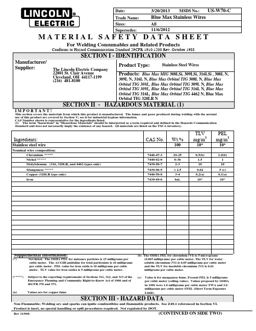
Date: 3/20/2013 MSDS No.: US-W70-CTrade Name: Blue Max Stainless WiresSizes: AllSupersedes: 11/6/2012M A T E R I A L S A F E T Y D A T A S H E E TFor Welding Consumables and Related ProductsConforms to Hazard Communication Standard 29CFR 1910.1200 Rev. October 1988SECTION I - IDENTIFICATIONManufacturer/Supplier:The Lincoln Electric Company22801 St. Clair AvenueCleveland, OH 44117-1199(216) 481-8100Product Type: Stainless Steel WiresProducts: Blue Max MIG 308LSi, 309LSi, 316LSi , 308L N, 309L N, 316L N, Blue Max Orbital TIG 308L N, Blue Max Orbital TIG 308L, Blue Max Orbital TIG 309L N, Blue Max Orbital TIG 309L, Blue Max Orbital TIG 316L N, Blue Max Orbital TIG 316L, Blue Max Orbital TIG 4462 N, Blue Max Orbital TIG 320LR NSECTION II - HAZARDOUS MATERIAL (1)I M P O R T A N T !This section covers the materials from which this product is manufactured. The fumes and gases produced during welding with the normal use of this product are covered by Section V; see it for industrial hygiene information.CAS Number shown is representative for the ingredients listed.(1) The term “hazardous” in “Hazardous Materials” should be interpreted as a term required and defined in the Hazards Communication Standard and does not necessarily imply the existence of any hazard. All materials are listed on the TSCA inventory.Product is inert, no special handling or spill procedures required. Not regulated by DOT.Rev 11/06b (CONTINUED ON SIDE TWO)Product: Blue Max Stainless WiresDate: 3/20/2013SECTION IV - HEALTH HAZARD DATAThreshold Limit Value: The ACGIH recommended general limit for Welding Fume NOS - (Not Otherwise Specified) is 5 mg/m3.ACGIH-1999 preface states that the TLV-TWA should be used as guides in the control of health hazards and should not be used as fine lines between safe and dangerous concentrations. See Section V for specific fume constituents which may modify this TLV. Threshold Limit Values are figures published by the American Conference of Government Industrial Hygienists. Units are milligrams per cubic meter of air.Effects of Overexposure: Electric arc welding may create one or more of the following health hazards:Fumes and Gases can be dangerous to your health. Common entry is by inhalation. Other possible routes are skin contact and ingestion.Short-term (acute) overexposure to welding fumes may result in discomfort such as metal fume fever, dizziness, nausea, or dryness or irritation of nose, throat, or eyes. May aggravate pre-existing respiratory problems (e.g. asthma, emphysema). Chromates present in the fume have beenknown to cause severe irritation of the bronchial tubes and lungs. Asthma has been reported.Long-term (chronic) overexposure to welding fumes can lead to siderosis (iron deposits in lung) and may affect pulmonary function. Manganese overexposure can affect the central nervous system, resulting in impaired speech and movement. Bronchitis and some lung fibrosis have been reported. Nickel and its compounds are on the IARC (International Agency for Research on Cancer) and NTP (National Toxicology Program) lists as posing a cancer risk to humans. Nickel compounds are skin sensitizers with symptoms usually occurring after repeated exposure - ranging from a slight itch to severe dermatitis. Chromates may cause ulceration and perforation of the nasal septum. Liver damage and allergic reactions, including skin rash, have been reported. Chromates contain the hexavalent form of chromium. Hexavalent chromium and its compounds are on the IARC (International Agency for Research on Cancer) and NTP (National Toxicology Program) lists as posing a cancer risk to humans.WARNING: This product contains or produces a chemical known to the State of California to cause cancer and birth defects (or other reproductive harm). (California Health & Safety Code Section 25249.5 et seq.)Arc Rays can injure eyes and burn skin. Skin cancer has been reported.Electric Shock can kill. If welding must be performed in damp locations or with wet clothing, on metal structures or when in cramped positions such as sitting, kneeling or lying, or if there is a high risk of unavoidable or accidental contact with workpiece, use the following equipment: Semiautomatic DC Welder, DC Manual (Stick) Welder, or AC Welder with Reduced Voltage Control.Emergency and First Aid Procedures: Call for medical aid. Employ first aid techniques recommended by the American Red Cross.IF BREATHING IS DIFFICULT give oxygen. IF NOT BREATHING employ CPR (Cardiopulmonary Resuscitation) techniques.IN CASE OF ELECTRICAL SHOCK, turn off power and follow recommended treatment. In all cases call a physician.SECTION V - REACTIVITY DATAHazardous Decomposition Products: Welding fumes and gases cannot be classified simply. The composition and quantity of both are dependent upon the metal being welded, the process, procedure and electrodes used.Other conditions which also influence the composition and quantity of the fumes and gases to which workers may be exposed include: coatings on the metal being welded (such as paint, plating, or galvanizing), the number of welders and the volume of the worker area, the qualityand amount of ventilation, the position of the welder's head with respect to the fume plume, as well as the presence of contaminants inthe atmosphere (such as chlorinated hydrocarbon vapors from cleaning and degreasing activities.)When the electrode is consumed, the fume and gas decomposition products generated are different in percent and form from theingredients listed in Section II. Decomposition products of normal operation include those originating from the volatilization, reaction,or oxidation of the materials shown in Section II, plus those from the base metal and coating, etc., as noted above.Reasonably expected fume constituents of this product would include: Primarily iron oxide, manganese oxide, and complex chromium oxides;secondarily complex oxides of copper, molybdenum and nickel when used with gas shielding.Maximum fume exposure guideline for this product based on manganese content is 0.1 milligrams per cubic meter when used with gas shielding.The OSHA PEL (Permissible Exposure Limit) is a ceiling value that shall not be exceeded at any time.Keep exposure as low as possible. Indoors, use local exhaust; outdoors, a respirator may be required.Gaseous reaction products may include carbon monoxide and carbon dioxide. Ozone and nitrogen oxides may be formed by the radiationfrom the arc.Determine the composition and quantity of fumes and gases to which workers are exposed by taking an air sample from inside the welder's helmet if worn or in the worker's breathing zone. Improve ventilation if exposures are not below limits. See ANSI/AWS F1.1, F1.2, F1.3 and F1.5, available from the American Welding Society, 550 N.W. LeJeune Road, Miami, FL 33126.SECTION VI AND VIICONTROL MEASURES AND PRECAUTIONS FOR SAFE HANDLING AND USE Read and understand the manufacturer's instruction and the precautionary label on the product. Request Lincoln Safety Publication E205. See American National Standard Z49.1, "Safety In Welding, Cutting and Allied Processes" published by the American Welding Society, 550 N.W. LeJeune Road, Miami, FL, 33126 (both available for free download at /community/safety/) and OSHA Publication 2206 (29CFR1910), U.S. Government Printing Office, Superintendent of Documents, P.O. Box 371954, Pittsburgh, PA 15250-7954 for more details on many of the following: Ventilation: Use enough ventilation, local exhaust at the arc, or both to keep the fumes and gases from the worker's breathing zone and the general area. Train the welder to keep his head out of the fumes. Keep exposure as low as possible.Respiratory Protection: Use respirable fume respirator or air supplied respirator when welding in confined space or general work area when local exhaust or ventilation does not keep exposure below TLV.Eye Protection: Wear helmet or use face shield with filter lens shade number 12 or darker. Shield others by providing screens and flash goggles. Protective Clothing: Wear hand, head, and body protection which help to prevent injury from radiation, sparks and electrical shock. See Z49.1.At a minimum this includes welder's gloves and a protective face shield, and may include arm protectors, aprons, hats, shoulder protection, as well as dark substantial clothing. Train the welder not to permit electrically live parts or electrodes to contact skin or clothing or gloves if they are wet. Insulate from work and ground.Disposal Information:Discard any product, residue, disposable container, or liner as ordinary waste in an environmentally acceptable manner accordingto Federal, State and Local Regulations unless otherwise noted. No applicable ecological information available.。
VTKG产品说明书
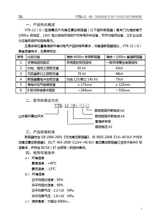
一、产品特点概述VTK-12(G)型弹簧式户内高压真空断路器(以下简称断路器)是专门为海拔高于1000m的地区,12kV电力系统开发的户内专用开关设备,可作为电网设备、工矿企业动力设备的保护和控制单元。
正是安装位置高海拔环境对电气产品的特殊要求,与普通断路器相比,VTK-12(G)具备显著特点,主要表现在:二、型号的表达方式额定短路开断电流kA山东泰开真空开关额定短路开断电流kA高海拔专用额定电压kV三、产品依据标准断路器符合GB 1984-2003《交流高压断路器》、JB 3855-2008《3.6~40.5kV户内交流高压真空断路器》、DL/T 403-2000《12kV~40.5kV高压真空断路器订货技术条件》标准要求,并符合IEC56(87出版物)的相关要求。
四、使用环境条件a)环境温度最高温度:+40℃最低温度:-15℃b)环境湿度日平均相对湿度:95%月平均相对湿度:90%日平均蒸气压:2.2×10 MPa月平均蒸气压:1.8×10 MPac)海拔高度:不超过4000m;d)地震烈度不超过8度;e)使用场所无滴水,无易燃和爆炸危险,无化学腐蚀性气体以及无剧烈震动。
五、产品结构及工作原理5.1 本体结构VTK-12(G)断路器主体部分采用固体绝缘结构,利用先进的环氧固封技术,将真空灭弧室、主导电回路、绝缘支撑等有机的结合成为一个集成固封极柱。
从根本上解决了真空断路器的环境耐受问题。
5.2 操动机构部分5.2.1弹簧操动机构(参见图1、图2)操动机构为弹簧储能操动机构,断路器框架内装有合闸单元,由一个或数个脱扣电磁铁组成的分闸单元,辅助开关,指示装置等部件;前方设有合、分按钮,手动储能操作孔,弹簧储能状态指示牌,合分指示牌等。
5.2.1.1 储能断路器合闸所需能量由合闸弹簧储能提供。
储能既可由外部电源驱动电机完成,也可以使用储能手柄完成。
储能操作:由固定在框架上的储能电机16进行,或者将储能手柄插入手动储能孔中逆时针摇动进行。
蓝星COD说明书

1.1 接线端子说明LXWA-O安装固定完成后,即可进行电源线和信号输出线的接线。
LXWA-O 接线端子在控制器的接线盒内,打开接线盒盖板,对照接线端子说明,按照需要进行电源和信号输出线的接线。
接线端子说明见表4.3.1。
注意: * 通讯端口通过接口上方的跳线配置为RS232或RS485模式: RS232模式: 1-4 OFF, 5-8 ON;RS485模式: 1-4 ON, 5-8 OFF;** 这些端口带有可以对人体造成危险或伤害的高电压,为了您的生命安全,请断电操作。
*** LXWA-O接地线必须按照有关标准可靠接地。
如果没有接地或接地不可靠,有可能造成LXWA-O不稳定或意外危险。
2水样取样和排放蠕动泵对水样的最大自由提升高度为1.5米,样水软管可直接插入污水池中,或者连接到外部取样管路上。
水样排放求自由排放,排放口不带压力,无阻力排放。
图6.1为取样和排放示意图。
(a) 水池取样(b) 管路取样图6.1取样和排放示意图3系统运行在LXWA-O完成安装和外部接线工作,并且检查完水样取样和排放等外围连接,正确无误以后,LXWA-O即可以投入正常使用。
本章主要讲述LXWA-O投运的步骤。
3.1 生物反应器中初始水样的加入生物反应器中初始水样的加入,可以通过直接加入的的方式,即先拔出搅拌电机部分,用容器盛被测量水样400mL,直接倒入生物反应中。
图8.1.1 初始水样的加入初始水样加入后,插入搅拌电机部分,注意,搅拌桨插入时,桨叶应稍微向溶解氧探头相反的方向倾斜。
然后,再按照第5章所述的安装过程将生物反应器安装到LXWA-O上并完成LXWA-O内部的联接。
3.2 LXWA-O通电运行8.1节所述过程完成后,首先要确认供电电源是否正确,如果符合3.1节所述的要求,LXWA-O就可以通电运行。
LXWA-O通电后,有两分钟的初始化过程,然后,LXWA-O进正常的测量过程。
如果初始水样温度较低,LXWA-O有一个加温过程(到30℃约10~30分钟),在此过程中,LXWA-O读数错误或没有读数,如果初始水样是首次加入,还需要经过4~24小时的驯化过程,才能得到正确的读数。
电磁保护设备TeSys GV系列产品参数表说明书
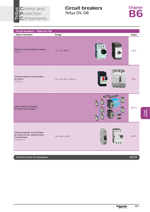
C i r c u i t b r e a k e r sCircuit breakersTeSys GV, GBC ontrol and P rotection C omponentsChapterB60.75g g 1.1g g 1.5375 2.533.5 LR2 K0308GV2LE071.1g g –––––– 2.533.5 LR2 K0308GV2LE071.5g g 1.5g g 3375451 LR2 K0310GV2LE08––– 2.2g g –––451 LR2 K0312GV2LE082.2g g 3501004375 6.378 LR2 K0312GV2LE103g g 410100 5.537510138 LR2 K0314GV2LE144g g 5.510100–––10138 LR2 K0316GV2LE14––––––7.537510138 LRD 14GV2LE14––––––937514170 LRD 16GV2LE165.515507.56751137514170 LR2 K0321GV2LE167.5155096751537518223 LRD 21GV2LE20915401147518.537525327 LRD 22GV2LE2211154015475–––25327 LRD 22GV2LE2215105018.54752237532416LRD 32GV2LE32(1) As % of Icu.g ) > 100 kA.GV2 LE10D F 526144.t i fC i r c u i t b r e a k e r s0.09––––––0.45LRD 03GV2L030.12g g –––0.37g g 0.638LRD 04GV2L040.18g g ––––––0.638LRD 04GV2L04––––––0.55g g 113LRD 05GV2L050.25g g ––––––113LRD 05GV2L05––––––0.75g g 113LRD 06GV2L050.37g g 0.37g g –––113LRD 05GV2L050.55g g 0.55g g 1.1g g 1.622.5LRD 06GV2L06–––0.75g g ––– 1.622.5LRD 06GV2L060.75g g 1.1g g 1.54100 2.533.5LRD 07GV2L07Example: GV3 L32 becomes GV3 L326.(1) As % of Icu. Associated current limiter or fuses, where required. See characteristics page B6/33.g > 100 kA.GV2 L10D F 526145.t i fGV3 L65D F 526146.t i fTeSys GVThermal-magnetic motor circuit breakers GV2 ME0.06gg––––––0.16…0.252.4GV2ME020.09g g––––––0.25…0.405GV2ME030.12 0.18g g g g – –– –– – 0.37 –g–g –0.40…0.638GV2ME040.25gg––– 0.55gg0.63…113GV2ME050.37 0.55 –g g –g g –0.37 0.55 0.75g g g g g g – 0.75 1.1– g g – g g 1…1622.5GV2ME060.75g g1.1gg1.5375 1.6...2.533.5GV2ME071.1 1.5g g g g 1.5 2.2g g g g 2.2 3 3 375 75 2.5 (4)51GV2ME082.2gg350100 43754...6.378GV2ME103 4g g g g 4 5.510 10100 100 5.5 7.5 3 375 756 (10)138GV2ME145.5 –15 –50 –7.5 – 6 –75 – 9 11 3 375 759…14170GV2ME167.5155096751537513…18223GV2ME209154011475 18.537517…23327GV2ME2111154015475 –––20…25327GV2ME22 (3)15105018.54752237524 (32)416GV2ME32Motor circuit breakers from 0.06 to 15 kW / 400 V, with lugsTo order thermal magnetic circuit breakers with connection by lugs, add the digit 6 to the end of reference selected above.Example: GV2 ME08 becomes GV2 ME086.Thermal magnetic circuit breakers GV2 ME with built-in auxiliary contact block With instantaneous auxiliary contact block (composition, see page B6/11):b GV AE1, add suffix AE1TQ to the motor circuit breaker reference selected above. Example: GV2 ME01AE1TQ .b GV AE11, add suffix AE11TQ to the motor circuit breaker reference selected above. Example: GV2 ME01AE11TQ .b GV AN11, add suffix AN11TQ to the motor circuit breaker reference selected above. Example: GV2 ME01AN11TQ .These circuit breakers with built-in contact block are sold in lots of 20 units in a single pack.(1) As % of Icu.(2) The thermal trip setting must be within the range marked on the graduated knob.(3) Maximum rating which can be mounted in enclosures GV2 MC or MP , please consult your Regional Sales Office. g > 100 kA.GV2 ME10D F 526134.t i fC i r c u i t b r e a k e r sTeSys GVTeSys protection componentsThermal-magnetic motor circuit breakers GV2 MEReferences0.06g g ––– 0.16…0.25 2.4GV2ME0230.09g g ––– 0.25…0.405GV2ME0330.120.18g g g g –––0.40…0.638GV2ME0430.250.37g g g g 0.37g g 0.63…113GV2ME0530.370.55g g g g 0.370.550.75g g g g g g 1…1.622.5GV2ME0630.75g g1.1g g 1.6…2.533.5GV2ME0731.11.5g g g g 1.52.2g g g g 2.5…451GV2ME0832.2g g 350100 4…6.378GV2ME10334g g g g 45.510101001006…10138GV2ME1435.515507.5675 9…14170GV2ME1637.515509675 13…18223GV2ME203911151540401147517…23327GV2ME2131115401547520 (25)327GV2ME223Contact blocksDescription Mounting Maximum number Type of contacts Sold in lots of Unitreference Instantaneous auxiliary contactsFront 1N/O + N/C 10GVAE113N/O + N/O 10GVAE203LH side2N/O + N/C 1GVAN113N/O + N/O1GVAN203AccessoryDescriptionApplicationSold in lots of Unitreference Cable end reducerFor connection of conductors from 1 to 1.5 mm 220LA9D99(1) For connection of conductors from 1 to 1.5 mm 2, the use of an LA9 D99 cable end reducer is recommended.(2) Maximum rating which can be mounted in enclosures GV2 MC or MP , please consult your Regional Sales Office (3) The thermal trip setting must be within the range marked on the graduated knob.g > 100 kA.GV2 ME pp 3D F 526135.t i fLA9 D99D F 533898.e p sTeSys GVReferencesTeSys protection componentsThermal-magnetic motor circuit breakersGV2 P, GV3 P and GV3 ME80GV2 P10D F 526137.t i fGV3 P65D F 526139.t i fGV3 P651D F 526140.t i fC i r c u i t b r e a k e r sTeSys GVReferences93610011181001581007.59707010010091150501001001115101010010012…20GV7RS20 2.0109113636100100111518181001001518.58810010015…25GV7RE25 2.0109117070100100111550501001001518.5101010010015…25GV7RS25 2.01018.53610018.522181810010022810025…40GV7RE40 2.01018.57010018.550100221010025…40GV7RS40 2.0102236100301810030810030…50GV7RE50 2.01522701003050100301010030 (50)GV7RS502.01537361004555181810010055810048...80GV7RE80 2.040377010045555050100100551010048...80GV7RS80 2.0404536100–1810075810060...100GV7RE100 2.0404570100–50100751010060...100GV7RS100 2.0405575353510010075903030100100901108810010090 (150)GV7RE1502.020557570701001007590505010010090110101010010090…150GV7RS150 2.02090110353510010011013216030303010010010016020088100100132…220GV7RE220 2.3509011070701001001101321605050501001001001602001010100100132…220GV7RS220 2.350(1) As % of lcu.TeSys protection componentsThermal-magnetic motor circuit breakers GV7 RGV7 RE40D F 526138.t i fGV7 RS220D F 526141.t i f0.12–0.120.180.18–0.370.40…0.6313GV2RT040.090.120.250.370.250.370.370.550.63…122GV2RT050.180.250.370.550.370.550.370.550.750.751.11…1.633GV2RT060.370.750.751.1 1.11.51.6…2.551GV2RT070.550.75 1.11.5 1.51.52.2 2.23 2.5…478GV2RT081.12.22.23344…6.3138GV2RT101.52.234445.5 5.57.56…10200GV2RT142.23 5.55.57.57.59119…14280GV2RT1647.57.5991513…18400GV2RT205.5911111118.517…23400GV2RT21(1) The thermal trip setting must be within the range marked on the graduated knob.GV2 RTD F 526142.t i fC i r c u i t b r e a k e r sblack handle, blue legend plate(1) The thermal trip setting must be within the range marked on the graduated knob.(2) Other accessories such as mounting, cabling and marking accessories are identical to those used for GV2 ME motor circuit breakers, see page B6/13.GV2 RTD F 526142.t i fD F 526340.e p sC i r c u i t b r e a k e r sTeSys GVDescription Mounting Maximum number Type of contacts Sold inlots of Unitreference Instantaneous auxiliary contactsFront (1)1N/O or N/C (2)10GVAE1N/O + N/C 10GVAE11N/O + N/O10GVAE20Side (LH)2N/O + N/C1GVAN11N/O + N/O1GVAN20Fault signalling contact + instantaneous auxiliary contact Side (3) (LH)1N/O (fault)+ N/O1GVAD1010+ N/C1GVAD1001N/C (fault)+ N/O1GVAD0110+ N/C1GVAD0101Short-circuit signalling contactSide (LH)1C/O common point1GVAM11(1 block on RH sideof circuit breaker GV2 ME)50 Hz GVAX11560 Hz GVAX116127 V60 Hz GVAX115220…240 V 50 Hz GVAX22560 Hz GVAX226380…400 V50 Hz GVAX38560 Hz GVAX386415…440 V 50 Hz GVAX415440 V60 Hz GVAX385Add-on contact blocksDescriptionMountingMaximum number Reference Visible isolation block (5)Front (1)1GV2AK00 (6)LimitersAt top(GV2 ME and GV2 P)1GV1L3Independent1LA9LB920(1) Mounting of a GV AE contact block or a GV2 AK00 visible isolation block on GV2 P and GV2 L .(2) Choice of N/C or N/O contact operation, depending on which way round the reversible block is mounted.(3) The GV AD is always mounted next to the circuit breaker.(4) To order an undervoltage trip: replace the dot (p ) in the reference with a U , example: GV AU025. To order a shunt trip: replace the dot (p ) in the reference with an S , example: GV AS025.(5) Visible isolation of the 3 poles upstream of circuit breaker GV2 P and GV2 L .Visible isolation block GV2 AK00 cannot be used with motor circuit breakers GV2 P32 and GV2 L32 (Ith max = 25 A).(6) Ie Max = 32 A.ReferencesTeSys protection componentsThermal-magnetic and magnetic motor circuit breakers GV2 with screw clamp connectionsAdd-on blocks and accessoriesCharacteristics:pages B6/89 and B6/94Dimensions, schemes:pages B6/70 to B6/82LA9LB920D B 126629.e p sC i r c u i t b r e a k e r sTeSys GVTerminal blockfor supply to one or more GV2 G busbar setsConnection from the top1GV1G09Can be fitted with current limiter GV1 L3 (GV2 ME and GV2 P)1GV2G05Cover for terminal block For mounting in modular panels10LA9E07Flexible 3-pole connection for connecting a GV2 to a contactor LC1-D09…D25 Centre distance between mounting rails: 100…120 mm10GV1G02Set of connections upstream/downstream For connecting GV2 ME to a printed circuit board 10GV2GA01“Large Spacing” adapter UL 508 type EFor GV2 P pp H7 (except 32 A)1GV2GH7Clip-in marker holders (supplied with each circuit breaker)For GV2 P , GV2 L, GV2 LE and GV2 RT (8 x 22 mm)100LA9D92ReferencesTeSys protection componentsThermal-magnetic and magnetic motor circuit breakers GV2 with screw clamp connectionsAccessoriesDimensions, schemes:pages B6/70 to B6/82D B 417942.e p sTeSys GVD B 126631.e p sD B 126630.e p sD B 126632.e p s7P B 106297_45.e p sExtended Rotary HandleAllows a circuit breaker or a starter-controller installed in back of an enclosure to be operated from the front of the enclosure.A rotary handle can be black or red/yellow, IP54 or IP65. It includes a function for locking the circuit breaker or the starter in the O (Off) or I (On) position(depending of the type of rotary handle) by means of up to 3 padlocks with a shank diameter of 4 to 8 mm. The extended shaft must be adjusted to use in different size enclosures. The IP54 rotary handle is fixed with a nut (Ø22) to make easierthe assembling. The new Laser Square tool brings the accuracy to align the circuit breaker and the rotary handle.device(padlocks not included)ReferencesTeSys protection componentsThermal-magnetic and magnetic motor circuit breakers GV2 with screw clamp connectionsC i r c u i t b r e a k e r sTeSys GVDescriptionMounting Maximum number Type of contacts Sold inlots of Unitreference Instantaneous auxiliary contactsFront1N/O or N/C (1)10GVAE1N/O + N/C 10GVAE11 (2)N/O + N/O10GVAE20 (2)Side (LH)2N/O + N/C1GVAN11 (2)N/O + N/O1GVAN20 (2)Fault signalling contact + instantaneous auxiliary contactFront 1N/O (fault)+ N/O1GVAED101 (2)N/O (fault)+ N/C1GVAED011 (2)Side (3) (LH)1N/O (fault)+ N/O1GVAD1010+ N/C1GVAD1001N/C (fault)+ N/O1GVAD0110+ N/C1GVAD0101Short-circuit signalling contact Side (LH)1C/O common point 1GVAM11(4)MountingVoltage ReferenceSide(1 block on RH side of circuit breaker)24 V 50 Hz GVA p 02560 Hz GVA p 02648 V 50 Hz GVA p 05560 Hz GVA p 05610050 Hz GVA p 107100…110 V 60 Hz GVA p 107110…115 V 50 Hz GVA p 11560 Hz GVA p 116120…127 V 50 Hz GVA p 125127 V 60 Hz GVA p 115200 V50 Hz GVA p 207200…220 V 60 Hz GVA p 207220…240 V 50 Hz GVA p 22560 Hz GVA p 226380…400 V 50 Hz GVA p 38560 Hz GVA p 386415…440 V 50 Hz GVA p 415415 V 60 Hz GVA p 416440 V 60 Hz GVA p 385480 V 60 Hz GVA p 415500 V 50 Hz GVA p 505600 V60 HzGVA p 505AccessoriesDescription Reference Sets of 3-pole 115 A busbars Pitch: 64 mm2 tap-off GV3 P pp and GV3 L pp GV3G2643 tap-off GV3 P pp and GV3 L pp GV3G364Cover “Large Spacing” UL 508 type E (Only one cover required on supply side)GV3 P ppGV3G66(1) Choice of N/C or N/O contact operation, depending on which way round the reversible block is mounted.(2) Contact blocks available in version with spring terminal connections. Add a figure 3 at the end of the references selected above. Example: GV AED101 becomes GV AED1013.(3) The GV AD pp is always mounted next to the circuit breaker.(4) To order an undervoltage trip: replace the dot (p ) in the reference with a U , example: GV AU025. To order a shunt trip: replace the dot (p ) in the reference with an S , example: GV AS025.Add-on blocks and accessoriesGV3 G66D F 537424.e p sTeSys GVD B 126637.e p sD B 126636.e p sD B 126632.e p s7P B 106297_45.e p sExtended Rotary HandleAllows a circuit breaker or a starter-controller installed in back of an enclosure to be operated from the front of the enclosure.A rotary handle can be black or red/yellow, IP54 or IP65. It includes a function for locking the circuit breaker or the starter in the O (Off) or I (On) position(depending of the type of rotary handle) by means of up to 3 padlocks with a shank diameter of 4 to 8 mm. The extended shaft must be adjusted to use in different size enclosures. The IP54 rotary handle is fixed with a nut (Ø22) to make easierthe assembling. The new Laser Square tool brings the accurency to align the circuit breaker and the rotary handle.For English 10-GVAPSEN For German 10-GVAPSDE For Spanish10-GVAPSES For Chinese 10-GVAPSCN For Portuguese 10-GVAPSPT For Russian 10-GVAPSRU For Italian10-GVAPSITD F 526342.e p sB6/21C i r c u i t b r e a k e r sTeSys GVfor locking the Start button (on open-mounted product)using up to 3 padlocks(padlocks to be ordered separately)External operator for mounting on enclosure door.Red Ø40 knob on yellow plate, padlockable in position O (with up to 3 padlocks). Door locked when knob in position I, and when knob padlocked in position O.GK3AP03(1) 1 voltage trip OR 1 fault signalling contact to be fitted inside the motor circuit breaker.Other versions24 to 690 V, 50 or 60 Hz voltage trips for circuit breakers GV3 ME80.Please consult your Regional Sales Office.ReferencesTeSys protection componentsMotor circuit breakers GV3 ME80 and GK3 EF80Add-on blocks and accessoriesCharacteristics:pages B6/89 and B6/92Dimensions:page B6/47B6/22D F 526344.e p sB6/23C i r c u i t b r e a k e r sTeSys GVThese allow remote indication of the circuit breaker contact states. They can be used for signalling, electrical locking, relaying, etc. They are available in two versions: standard and low level. They include a terminal block and the auxiliary circuits leave the circuit breaker through a hole provided for this purpose.They perform the following functions, depending on where they are located in the circuit breaker:Low levelGV7AB11Fault discrimination devicesThese make it possible to:b either differentiate a thermal fault from a magnetic fault,b or open the contactor only in the event of a thermal fault.VoltageReference a 24...48 and c 24…72 V GV7AD111 (1)z 110…240 VGV7AD112 (1)Electric tripsThese allow the circuit breaker to be tripped via an electrical control signal.b Undervoltage trip GV7 AUv Trips the circuit breaker when the control voltage drops below the tripping threshold, which is between 0.35 and 0.7 times the rated voltage.v Circuit breaker closing is only possible if the voltage exceeds 0.85 times the rated voltage. Circuit breaker tripping by a GV7 AU trip meets the requirements of IEC 60947-2.b Shunt trip GV7 ASTrips the circuit breaker when the control voltage rises above 0.7 times the rated voltage.b Operation (GV7 AU or GV7 AS)v When the circuit breaker has been tripped by a GV7 AU or AS, it must be reset either locally or by remote control. (For remote control, please consult your Regional Sales Office).v Tripping has priority over manual closing: if a tripping instruction is present, manual action does not result in closing, even temporarily, of the contacts.v Durability: 50 % of the mechanical durability of the circuit breaker.TypeVoltageReference Undervoltage trip48 V, 50/60 HzGV7AU055 (1)110…130 V, 50/60 Hz GV7AU107 (1)200…240 V, 50/60 Hz GV7AU207 (1)380…440 V, 50/60 Hz GV7AU387 (1)525 V, 50 HzGV7AU525 (1)Shunt trip48 V, 50/60 HzGV7AS055 (1)110…130 V, 50/60 Hz GV7AS107 (1)200…240 V, 50/60 Hz GV7AS207 (1)380…440 V, 50/60 Hz GV7AS387 (1)525 V, 50 HzGV7AS525 (1)(1) For mounting of a GV7 AD or a GV7 AU or AS.ReferencesTeSys protection componentsThermal-magnetic motor circuit breakers GV7 R with screw clamp connectionsAdd-on blocks and accessoriesCharacteristics:pages B6/51, B6/52 and B6/56Dimensions:pages B6/79 to B6/81Schemes:page B6/83B6/24B6/25C i r c u i t b r e a k e r sTeSys GVDescription ApplicationFor use on contactors Sold in lots of Unitreference Clip-on connectors for GV7 RUp to 150 A, 1.5…95 mm 2–3GV7AC021Up to 220 A, 1.5…185 mm 2–3GV7AC022Spreader 3-pole (1)To increase the pitch to 45 mm–1GV7AC03Terminal shields IP 405 (1)Supplied with sealing accessory–1GV7AC01Phase barriersSafety accessories used when fitting of shields is impossible –2GV7AC04Insulating screens Ensure insulation between the connections and the backplate –2GV7AC05Kits for combination with contactor (2)Allowing link between thecircuit breaker and the contactor. The cover provides protection against direct finger contactLC1 F115…F1851GV7AC06LC1 F225 and F2651GV7AC07LC1 D115 and D1501GV7AC08Replaces the circuit breaker front cover; secured by screws. It includes a device for locking the circuit breaker in the O (Off) position by means of up to 3 padlocks with a shank diameter of 5 to 8 mm (padlocks not included). A conversion accessory allows the direct rotary handle to be mounted on the enclosure door. In this case, the door cannot be opened if the circuit breaker is in the “ON” position. Circuit breaker closing is inhibited if the enclosure door is open.Description TypeDegree of protection Reference Direct rotary handleBlack handle, black legend plate IP 40GV7AP03Red handle, yellow legend plateIP 40GV7AP04Adapter plate (3)Four mounting direct rotary handle on enclosure doorIP 43GV7AP05Allows a circuit breaker installed in the back of an enclosure to be operated from the front of the enclosure. It comprises:b a unit which screws onto the front cover of the circuit breaker,b an assembly (handle and front plate) to be fitted on the enclosure door,b an extension shaft which must be adjusted (distance between the mounting surface and the door: 185 mm minimum, 600 mm maximum). It includes a device for locking the circuit breaker in the O (Off) position by means of up to 3 padlocks with a shank diameter of 5 to 8 mm (padlocks not included). This prevents the enclosure door from being opened.DescriptionTypeDegree of protection Reference Extended rotary handleBlack handle, black legend plate IP 55GV7AP01Red handle, yellow legend plateIP 55GV7AP02Allows circuit breakers not fitted with a rotary handle to be locked in the O (Off) position by means of up to 3 padlocks with a shank diameter of 5 to 8 mm (padlocks not included).Description ApplicationReference Locking deviceFor circuit breaker not fitted with a rotary handleGV7V01(1) Terminal shields cannot be used together with spreaders.(2) The kit comprises links, a protective shield and a depth adjustable metal bracket for the breaker.(3) This conversion accessory makes it impossible to open the door if the device is closed and prevents the device from being closed if the door is open.ReferencesTeSys protection componentsThermal-magnetic motor circuit breakers GV7 R with screw clamp connectionsAccessoriesGV7 AC07D F 537429.e p sGV7 AC08D F 537428.e p sDimensions:pages B6/79 to B6/81B6/260.5 6.63GB2DB051143GB2DB062263GB2DB073403GB2DB084503GB2DB095663GB2DB106833GB2DB1281083GB2DB14101383GB2DB16121653GB2DB20162203GB2DB21202703GB2DB22(1) Conforming to IEC 60947-1.GB2 CBppD F 526243.t i fGB2 CD ppD F 526244.t i fGB2 DBppD F 526245.t i fPresentation, selection :page B6/84Characteristics :pages B6/85 to B6/87Dimensions :page B6/88Schemes :page B6/88B6/27C i r c u i t b r e a k e r s(1) Conforming to IEC 60947-1.Accessories for circuit breakers GB2-CB, DB and CSDescriptionSold in lots of Unitreference Busbar set for supply to 10 GB2 DB or20 GB2 CB or GB2 CS with 2 connectors1GB2G210Supply connector 10GB2G01GB2 CS ppD F 526246.t i fPresentation, selection :page B6/84Characteristics :pages B6/85 to B6/87Dimensions :page B6/88Schemes :page B6/88B6/28B6/29B6/30TeSys GVCharacteristicsTeSys protection componentsMagnetic motor circuit breakers GV2 LE and GV2 LReferences:pages B6/2 and B6/3Dimensions:pages B6/43 to B6/47Schemes:page B6/48add-on contact blocks. Side by side mounting is possible up to 40 °C.(2) When mounting on a vertical rail, fit a stop to prevent any slippage.(1) As % of Icu.Average operating times at 20 °C related to multiples of the setting currentD F 534092.e p s1 3 poles from cold state2 2 poles from cold state3 3 poles from hot stateDynamic stressI peak = f (prospective Isc) at 1.05 Ue = 435 VD F 534093.e p s1 Maximum peak current2 32 A3 25 A4 18 A5 14 A6 10 A7 6.3 A8 4 A9 2.5 A 10 1.6 A11 Limit of rated ultimate breaking capacity on short-circuit of GV2 LE (14, 18, 23 and 25 A ratings).Dynamic stressI peak = f (prospective Isc) at 1.05 Ue = 435 VD F 534094.e p s1 Maximum peak current2 32 A3 25 A4 18 A5 14 A6 10 A7 6.3 A8 4 A9 2.5 A 10 1.6 A11 Limit of rated ultimate breaking capacity on short-circuit of GV2 LE (14, 18, 23 and 25 A ratings).Thermal limit in kA 2s in the magnetic operating zone Sum of I 2dt = f (prospective Isc) at 1.05 Ue = 435 V22Prospective Isc (kA)D F 534095.e p s1 32 A 2 25 A3 18 A4 14 A5 10 A6 6.3 A7 4 A8 2.5 A9 1.6 AThermal limit in kA 2s in the magnetic operating zone Sum of I 2dt = f (prospective Isc) at 1.05 Ue = 435 V22D F 534096.e p s1 25 A and 32 A 2 18 A3 14 A 4 10 A5 6.3 A6 4 A7 2.5 A8 1.6 AThermal limit in kA 2s in the magnetic operating zone Sum of I 2dt = f (prospective Isc) at 1.05 Ue = 435 V22D F 534097.e p s1 32 A (GV2 LE32)2 25 A and 32 A (GV2 L32)3 18 A4 14 A5 10 A6 6.3 A7 4 A8 2.5 A9 1.6 A10 Limit of rated ultimate breaking capacity on short-circuit of GV2 LE (14, 18, 23 and 25 A ratings).Average operating time at 20 °C without prior current flowx the setting current (Ir)D F 534098.e p s1 3 poles from cold state2 2 poles from cold state3 3 poles from hot stateA Thermal overload relay protection zoneB GV3 L protection zoneDynamic stressI peak = f (prospective Isc) at 1.05 Ue = 435 VProspective Isc (kA)D B 418280.e p s1 Maximum peak current2 GV3 L653 GV3 L504 GV3 L405 GV3 L326 GV3 L25Thermal limit in A 2sSum of I 2dt = f (prospective Isc) at 1.05 Ue = 435 V2Prospective Isc (kA)D B 418279.e p s1 GV3 L652 GV3 L503 GV3 L404 GV3 L325 GV3 L25TeSys GVDimensions, mountingD F 537440.e p sD F 537441.e p sD F 537444.e p sTeSys protection componentsMagnetic motor circuit breakers GV2 L and GV2 LETeSys GVDimensions, mounting TeSys protection componentsMagnetic motor circuit breakers GV2 L and GV2 LED B 127415.e p sD B 127414.e p sa b Mini Maxi Mini Maxi GV2 APN pp140250GV2 APN pp + GV APH02151250GV2 APN pp + GV APK11250434--GV2 APN pp + GV APH02 + GV APK11--250445TeSys GVDimensions,mounting Sets of busbars GV2 G445, GV2 G454, GV2 G472, with terminal block GV2 G05D F 537451.e p sGV2 G445224269314359GV2 G454260314368422GV2 G472332404476548D F 537452.e p sD F 537454.e p sGV2 G345 (3 x 45 mm)134GV2 G354 (3 x 54 mm)152TeSys protection componentsMagnetic motor circuit breakers GV2 L and GV2 LED F 537480.e psD F 537435.e p sD F 510637.e p sD F 510638.e p sD B 127416.e p sD B 127417.e p sa b Mini Maxi Mini Maxi GV3 APN pp189300--GV3 APN pp + GV APK12300481GV3 APN pp + GV APH03--200300GV3 APN pp + GV APH03 + GV APK12--300492TeSys GVSchemesTeSys protection componentsMagnetic motor circuit breakers GV2 L, GV2 LE, GV3 LD F 537474.e p sD F 537475.e p sD F 537476.e p sGV2 ME, GV2 P , GV3 ME, GV3 P and GV7 R motor circuit breakers are 3-pole thermal-magnetic circuit breakers specifically designed for the control and protection of motors , conforming to standards IEC 60947-2 and IEC 60947-4-1.Connection GV2GV2 ME and GV2 P circuit breakers are designed for connection by screw clamp terminals.Circuit breaker GV2 ME can be supplied with lugs or spring terminal connections.Spring terminal connections ensure secure, permanent and durable clamping that is resistant to harsh environments, vibration and impact and are even more effective when conductors without cable ends are used. Each connection can take two independent conductors.GV3GV3 circuit breakers feature connection by BTR screws (hexagon socket head), tightened using a n° 4 Allen key.This type of connection uses the Ever Link ® system with creep compensation (1) (Schneider Electric patent).This technique makes it possible to achieve accurate and durable tightening torque, in order to avoid cable creep.GV3 circuit breakers are also available with connection by lugs. This type of connection meets the requirements of certain Asian markets and is suitable for applications subject to strong vibration, such as railway transport.GV7GV7 circuit breakers: with connection by screw clamp terminals (for bars and lugs) and by clip-on connectors.OperationControl is manual and local when the motor circuit breaker is used on its own.Control is automatic and remote when it is associated with a contactor.GV2 ME and GV3 ME80Pushbutton control.Energisation is controlled manually by operating the Start button “I” 1.De-energisation is controlled manually by operating the Stop button “O” 2, or automatically by the thermal-magnetic protection elements or by a voltage trip attachment.GV2 P , GV3 P and GV7 Rb Control by rotary knob: for GV2 P and GV3 P b Control by rocker lever: for GV7 R.Energisation is controlled manually by moving the knob or rocker lever to position “I” 1.De-energisation is controlled manually by moving the knob or rocker lever to position “O” 2.De-energisation due to a fault automatically places the knob or rocker lever in the “Trip” position 3.Re-energisation is possible only after having returned the knob or rocker lever to position “O”.(1) Creep: normal crushing phenomenon of copper conductors, that is accentuated over time.GV2 MEwith screw clamp terminals124D F 526134.t i fGV2 MEwith spring terminals connections124D F 526135.t i fGV3 P1324D F 526136.t ifGV2 P1342D F 526137.t i fGV7 R132D F 526138.t i f。
- 1、下载文档前请自行甄别文档内容的完整性,平台不提供额外的编辑、内容补充、找答案等附加服务。
- 2、"仅部分预览"的文档,不可在线预览部分如存在完整性等问题,可反馈申请退款(可完整预览的文档不适用该条件!)。
- 3、如文档侵犯您的权益,请联系客服反馈,我们会尽快为您处理(人工客服工作时间:9:00-18:30)。
Vishay SemiconductorsVLMG31..Standard SMD LED in PLCC-2FEATURES•Lead (Pb)-free product-RoHS compliant •SMD LEDs with exceptional brightness •Luminous intensity categorized•Compatible with automatic placementequipment•EIA and ICE standard package•Compatible with IR reflow, vapor phase and wave solder processes according to CECC 00802 and J-STD-020C•Available in 8 mm tape •Low profile package•Non-diffused lens: excellent for coupling to light pipes and backlighting •Low power consumption •Luminous intensity ratio in one packaging unit I Vmax /I Vmin ≤ 1.6•Preconditioning: acc. to JEDEC level 2a •ESD-withstand voltage:up to 2 kV according to JESD22-A114-B 948553DESCRIPTIONThese devices have been designed to meet the increasing demand for surface mounting technology.The package of the VLMG31-series is the PLCC-2.It consists of a lead frame which is embedded in a white thermoplast. The reflector inside this package is filled up with clear epoxy.PRODUCT GROUP AND PACKAGE DATA •Product group: LED •Package: SMD PLCC-2 •Product series: standard •Angle of half intensity: ± 60°APPLICATIONS •Automotive: backlighting in dashboards and switches •Telecommunication: indicator and backlighting in telephone and fax •Indicator and backlight for audio and video equipment•Indicator and backlight in office equipment •Flat backlight for LCDs, switches and symbols •General usePARTS TABLEPARTCOLOR, LUMINOUS INTENSITY TECHNOLOGY VLMG31K1L2-GS08Green, I V = (7.1 to 18) mcd GaP on GaP VLMG31K1L2-GS18Green, I V = (7.1 to 18) mcd GaP on GaP VLMG31K1M2-GS08Green, I V = (7.1 to 28) mcd GaP on GaP VLMG31K1M2-GS18Green, I V = (7.1 to 28) mcd GaP on GaP VLMG31L1M2-GS08Green, I V = (11.2 to 28) mcd GaP on GaP VLMG31L1M2-GS18Green, I V = (11.2 to 28) mcdGaP on GaPVishay SemiconductorsVLMG31..Note:1) Tamb = 25°C, unless otherwise specified2) Driving LED in reverse direction is suitable for short term application.Note:1) Tamb = 25°C, unless otherwise specified2) in one packing unit IVmax/I Vmin≤ 1.6Note:Luminous intensity is tested at a current pulse duration of 25 ms andan accuracy of ± 11 %.The above Type Numbers represent the order groups which include only a few brightness groups. Only one group will be shipped on each reel (there will be no mixing of two groups on each reel). In order to ensure availability, single brightness groups will not be orderable.In a similar manner for colors where wavelength groups are measured and binned, single wavelength groups will be shipped on any one reel.In order to ensure availability, single wavelength groups will not be orderable.Note:Wavelengths are tested at a current pulse duration of 25 ms and an accuracy of ± 1 nm.ABSOLUTE MAXIMUM RATINGS1) VLMG31..PARAMETER TEST CONDITION SYMBOL VALUE UNIT Reverse voltage2)V R6V DC forward current T amb≤ 60°C I F30mA Surge forward current t p≤ 10 µs I FSM0.5A Power dissipation P V100mW Junction temperature T j100°C Operating temperature range T amb- 40 to + 100°C Storage temperature range T stg- 40 to + 100°CThermal resistance junction/ ambient mounted on PC board(pad size > 16 mm2)R thJA400K/WOPTICAL AND ELECTRICAL CHARACTERISTICS1) VLMG31.., GREENPARAMETER TEST CONDITION PART SYMBOL MIN TYP.MAX UNITLuminous intensity2)I F = 10 mA VLMG31K1L2I V7.118mcd VLMG31K1M2I V7.128mcd VLMG31L1M2I V11.228mcdDominant wavelength I F = 10 mAλd562575nm Peak wavelength I F = 10 mAλp565nm Angle of half intensity I F = 10 mAϕ± 60deg Forward voltage I F = 20 mA V F 2.2 2.8V Reverse voltage I R = 10 µA V R615V Junction capacitance V R = 0, f = 1 MHz C j15pFLUMINOUS INTENSITY CLASSIFICATION GROUP LIGHT INTENSITY (MCD) STANDARD OPTIONAL MIN MAX K17.192911.2 L111.214.0214.018.0 M118.022.4222.428.0COLOR CLASSIFICATIONGROUP GREENDOM. WAVELENGTH (NM)MIN. MAX.356256545645675566569656857175705738572575CROSSING TABLEVISHAY OSRAM VLMG31K1L2LGT670-K1L2VLMG31K1M2LGT670-K1M2VLMG31L1M2LGT670-L1M2Vishay SemiconductorsVLMG31..TYPICAL CHARACTERISTICST amb = 25°C, unless otherwise specifiedFigure 1. Forward Current vs. Ambient TemperatureFigure 2. Pulse Forward Current vs. Pulse Duration Figure 3. Rel. Luminous Intensity vs. Angular Displacement 01020304060I F - F o r w a r d C u r r e n t (m A )95 1090550T am b - Am b ient Temperat u re (°C)100806040200.010.111010100t p - P u lse Length (ms)10095 9985I - F o r w a r d C u r r e n t (m A )F 0.40.20.20.40.695 103190.60.90.80°30°10°20°40°50°60°70°80°0.71.0I V r e l- R e l a t i v e L u m i n o u s I n t e n s i t yFigure 4. Relative Intensity vs. WavelengthFigure 5. Forward Current vs. Forward VoltageFigure 6. Specific Luminous Intensity vs. Forward Current52054056058060000.20.40.60.81.262095 10038λ - W a v elength (nm)1.0I - R e l a t i v e L u m i n o u s I n t e n s i t yV r e l 0.1110100V F - For w ardV oltage (V )I - F o r w a r d C u r r e n t (m A )F 5210395 99864Vishay SemiconductorsVLMG31..PACKAGE DIMENSIONS in millimetersFigure7. Rel. Luminous Intensity vs. Ambient TemperatureVishay SemiconductorsVLMG31..METHOD OF TAPING/POLARITY AND TAPE AND REELSMD LED (VLM3 - SERIES)Vishay’s LEDs in SMD packages are available in an antistatic 8 mm blister tape (in accordance with DIN IEC 40 (CO) 564) for automatic component insertion. The blister tape is a plastic strip with impressed component cavities, covered by a top tape.TAPING OF VLM.3..REEL PACKAGE DIMENSION IN MM FOR SMD LEDS, TAPE OPTION GS08 (= 1500 PCS.)REEL PACKAGE DIMENSION IN MM FOR SMD LEDS, TAPE OPTION GS18 (= 8000 PCS.) PREFERREDSOLDERING PROFILEFigure 8. Tape Dimensions in mm for PLCC-2Figure9. Reel Dimensions - GS08Figure 10. Reel Dimensions - GS18Figure 11. Vishay Lead (Pb)-free Reflow Soldering Profile(acc. to J-STD-020C)Figure 12. Double Wave Soldering of Opto Devices (all Packages)Vishay Semiconductors VLMG31..BAR CODE PRODUCT LABELEXAMPLE:A)Type of componentB)Manufacturing plantC)SEL - selection code (bin):e.g.:K1= code for luminous intensity group4 = code for color groupD)Date code year/weekE)Day code (e.g. 2: Tuesday)F)Batch no.G)Total quantityH)Company codeDRY PACKINGThe reel is packed in an anti-humidity bag to protect the devices from absorbing moisture during transportation and storage.FINAL PACKINGThe sealed reel is packed into a cardboard box. A secondary cardboard box is used for shipping purposes.RECOMMENDED METHOD OF STORAGEDry box storage is recommended as soon as the aluminium bag has been opened to prevent moisture absorption. The following conditions should be observed, if dry boxes are not available:• Storage temperature 10°C to 30°C• Storage humidity ≤ 60 % RH max.After more than 672 h under these conditions moisture content will be too high for reflow soldering.In case of moisture absorption, the devices will recover to the former condition by drying under the following condition:192 h at 40°C + 5°C/- 0°C and < 5 % RH (dry air/ nitrogen) or96 h at 60°C + 5°C and < 5 % RH for all device containers or24 h at 100°C + 5°C not suitable for reel or tubes. An EIA JEDEC standard JESD22-A112 level 2a label is included on all dry bags.ESD PRECAUTIONProper storage and handling procedures should befollowed to prevent ESD damage to the devicesespecially when they are removed from the antistaticshielding bag. Electro-static sensitive devices warninglabels are on the packaging.VISHAY SEMICONDUCTORS STANDARDBAR CODE LABELSThe Vishay Semiconductors standard bar code labelsare printed at final packing areas. The labels are oneach packing unit and contain Vishay Semiconductorsspecific data.V ISHAYA HVLMG31..Vishay SemiconductorsOZONE DEPLETING SUBSTANCES POLICY STATEMENTIt is the policy of Vishay Semiconductor GmbH to1.Meet all present and future national and international statutory requirements.2.Regularly and continuously improve the performance of our products, processes, distribution and operatingsystems with respect to their impact on the health and safety of our employees and the public, as well as their impact on the environment.It is particular concern to control or eliminate releases of those substances into the atmosphere which are known as ozone depleting substances (ODSs).The Montreal Protocol (1987) and its London Amendments (1990) intend to severely restrict the use of ODSs and forbid their use within the next ten years. Various national and international initiatives are pressing for an earlier ban on these substances.Vishay Semiconductor GmbH has been able to use its policy of continuous improvements to eliminate the use of ODSs listed in the following documents.1.Annex A, B and list of transitional substances of the Montreal Protocol and the London Amendments respectively2.Class I and II ozone depleting substances in the Clean Air Act Amendments of 1990 by the EnvironmentalProtection Agency (EPA) in the USA3.Council Decision 88/540/EEC and 91/690/EEC Annex A, B and C (transitional substances) respectively. Vishay Semiconductor G mbH can certify that our semiconductors are not manufactured with ozone depleting substances and do not contain such substances.We reserve the right to make changes to improve technical designand may do so without further notice.Parameters can vary in different applications. All operating parameters must be validated for each customer application by the customer. Should the buyer use Vishay Semiconductors products for any unintended or unauthorized application, the buyer shall indemnify Vishay Semiconductors against all claims, costs, damages, and expenses, arising out of, directly or indirectly, any claim of personal damage, injury or deathassociated with such unintended or unauthorized use.Vishay Semiconductor GmbH, P.O.B. 3535, D-74025 Heilbronn, GermanyDisclaimer Legal Disclaimer NoticeVishayAll product specifications and data are subject to change without notice.Vishay Intertechnology, Inc., its affiliates, agents, and employees, and all persons acting on its or their behalf (collectively, “Vishay”), disclaim any and all liability for any errors, inaccuracies or incompleteness contained herein or in any other disclosure relating to any product.Vishay disclaims any and all liability arising out of the use or application of any product described herein or of any information provided herein to the maximum extent permitted by law. The product specifications do not expand or otherwise modify Vishay’s terms and conditions of purchase, including but not limited to the warranty expressed therein, which apply to these products.No license, express or implied, by estoppel or otherwise, to any intellectual property rights is granted by this document or by any conduct of Vishay.The products shown herein are not designed for use in medical, life-saving, or life-sustaining applications unless otherwise expressly indicated. Customers using or selling Vishay products not expressly indicated for use in such applications do so entirely at their own risk and agree to fully indemnify Vishay for any damages arising or resulting from such use or sale. Please contact authorized Vishay personnel to obtain written terms and conditions regarding products designed for such applications.Product names and markings noted herein may be trademarks of their respective owners.元器件交易网。