SIHLZ14中文资料
ED15M44SLEZ中文资料(Positronic)中文数据手册「EasyDatasheet - 矽搜」
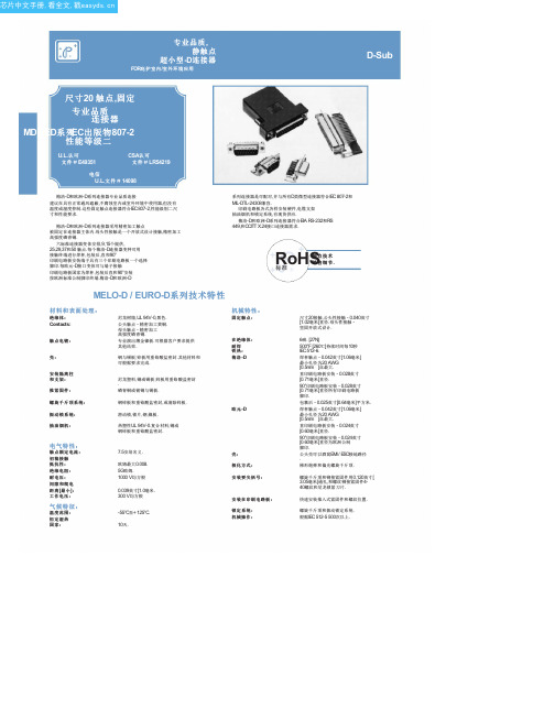
MD / ED系列
0.135 [3.43] 0.352 [8.94]
对于焊杯触点 ,指定 在步骤 4代码 2
订购信息.
典型型号: ED15M200T2Z
修正公头性和母头性提供偏光螺旋千斤顶. 指定订购信息步骤 7码 T6.
典型型号: MD15M200T6Z
直印刷电路板安装连接器
CODE NUMBER
HDC
6 0.375 [9.53] 0.360 [9.14]
指定订购信息步骤 6代码 F或 Q. F代表铁 素体电感和 Q为铁素体电感与推入式紧固件 .
L 90°印 刷 电 路 板 安 装 连 接 器
铁素体电感酒吧
A
0.135±0.005 [3.43±0.13]
Fixed female jackscrews
六标准连接器变体安排,9,15个提供, 25,29,37和50 触点.每个梅洛-D连接器变种可用 接触终端进行焊杯,包装后,直和90°
印刷电路板安装端子具有三个印刷电路板一个选择
脚印.每欧元-D接口变体可与端子接触 印刷电路板国家为焊杯,包装后直和90°安装 按欧洲标准公制脚印终端.梅洛-D和欧洲-D
钢与锡板;锌板用重铬酸盐密封.其他材料和 可根据要求完成.
尼龙塑料,铜或锡板;锌板用重铬酸盐密封 . 磷青铜或铍铜与锡板.
钢锌板和重铬酸盐密封,或清除锌板.
滑动锁,锁片,钢,镍板.
热塑性UL 94V-0.复合材料,铜或 钢锌板和重铬酸盐密封.
机械特性:
固定触点:
在绝缘体: 耐焊 铁热:
梅洛 -D
欧元 -D
可选壳件
与环球 FLOAT支架 [F]
0.120±0.010 [3.05±0.25]
ANSI ASQZ1.4抽样检验技术
7.2檢查水平等級 7.2.1一般檢查水平 一般檢查水平分為三級:一般檢查水平I;一般檢 查水平II;一般檢查水平III。 判斷能力:III>II>I。 7.2.2 特殊檢查水平 特殊檢查水平分為四級:特殊檢查水平S-1;特殊 檢查水平S-2;特殊檢查水平S-3;特殊檢查水平 S-4。 判斷能力:S-4>S-3>S-2>S-1。一般檢查水平的 判斷能力大於特殊檢查水平的判斷能力。即: III>II>I >S-4>S-3>S-2>S-1 7.3檢查水平的選擇原則 沒有特別規定時,首先採用一般檢查水平II;
繼續抽樣的結論。若結論為繼續抽檢,按規定 樣本大小作第二次抽樣檢查,據累計抽樣檢查 結果判定批合格或批不合格。 5.2.3 多次抽樣。多次抽樣檢驗是二次抽樣 檢驗的擴展。每次均按規定的樣本大小抽樣並 作檢查,將各次抽檢結果累計與判定數組比較, 作出合格、不
合格或繼續抽檢的結論,直至抽檢次數可 作出合格或不合格判定為止。中國規定有 五次抽樣檢查,美國規定有七次抽樣。 5.2.4 序貫抽樣。序貫抽樣檢查每次隻抽 取一個樣品檢查,一個或若幹個樣品檢查 後,將累計檢查結果與相應的判斷標准作 比較﹐作出合格﹑不合格或繼續抽驗的結 論。
6.合格質量水平 AQL
6.1.AQL 的概念與意義 合格質量水平AQL(Acceptable Quality Level),也稱品質允收水準。它表征連續提 交批平均不合格率的上限值,它是計數調整型 抽樣檢查對交驗批的質量標準。AQL 以每百 單位產品的不合格數或不合格數表示。在數值 上它等於過程平均不合格品率上限值p max , 它是允許的不良再壞的批質量平均值。
瑞典模具钢

X13T6W(236)电渣重溶模具材料详细介绍:X13T6W(236H)电渣重溶模具钢材详细介绍:MEK4/DIN1.8523高耐磨塑胶模具钢详细介绍:高温热作模具用合金BC-3详细介绍:高温热作模具用合金BC-3材料介绍热挤压材料BC-3是一种新型特种合金材料,适应于800℃以上应用的热加工领域。
具有良好的稳定性和耐磨性及红硬性,同时具有优良的抗急冷急热和抗高温氧化性能,在温度650℃时具有良好的综合性能,是一种理想的热挤压材料。
现用于制作有色金属铜及铜金合金的挤压。
其使用寿命比一般热作模具钢可提高五到十倍,并且挤制的产品表面质量好,尺寸精确度高,而且使用寿命长,应用到铜加工行业已有多年的历史。
一、新型特种钢BC-3热挤压材料的主要性能1、机械性能2、持久性能3、蠕变和疲劳性能4抗氧化数据5、长期时效性能热挤压模具是有色金属挤压生产中使用的关键工具,热挤压模具的使用寿命和质量,极大影响着挤压制品的质量、挤压制品表面质量不好,尺寸精度差,因而需要频繁更换模具,生产效率太低,产品成品率低,磨具消耗量大。
我们开发研制的BC-3合金材料已经解决了铜及压的多种难题。
几年来,已经在全国铜挤压领域肿,去得了显著的经济效益和社会效益并充分显示了这种新型材料的显著优越性。
1、提高生产效率BC-3材料使用寿命长。
使用寿命是H13钢的5-10倍,可以为企业减少大量热停修模的时间。
2、提高产品质量BC-3的红硬性高,耐磨性好。
使用中不变形,不氧化,表面光滑不沾铜。
所挤制的产品表面质量好,尺寸精确度高,为拉伸工序和定尺控制提供了良好条件。
消除了使用热作钢模具时的粘铜、划伤等现象。
3、提高产品成品率使用BC-3材料挤压出的铜材表面光洁,成品率高。
4、减低模具费用热挤压生产中,挤压模消耗量大,占生产的比重也高,使用BC-3材料是热作钢模具使用寿命的5-10倍,并且减少大量的模具机加工费用。
其经济效益和社会效益显著。
为实现热挤压产品高产、优质、低耗提供了保证,为有色金属加工业的可持续发展创造了良好的条件。
欧洲品牌电磁器件型号123456产品说明书
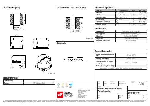
Dimensions: [mm]Scale - 5:174404054047BC74404054047T e m p e r a t u r eT pT L74404054047Cautions and Warnings:The following conditions apply to all goods within the product series of WE-LQS of Würth Elektronik eiSos GmbH & Co. KG:General:•This electronic component is designed and manufactured for use in general electronic equipment.•Würth Elektronik must be asked for written approval (following the PPAP procedure) before incorporating the components into any equipment in fields such as military, aerospace, aviation, nuclear control, submarine, transportation (automotive control, train control, ship control), transportation signal, disaster prevention, medical, public information network etc. where higher safety and reliability are especially required and/or if there is the possibility of direct damage or human injury.•Electronic components that will be used in safety-critical or high-reliability applications, should be pre-evaluated by the customer. •The component is designed and manufactured to be used within the datasheet specified values. If the usage and operation conditions specified in the datasheet are not met, the wire insulation may be damaged or dissolved.•Do not drop or impact the components, the component may be damaged.•Würth Elektronik products are qualified according to international standards, which are listed in each product reliability report. Würth Elektronik does not warrant any customer qualified product characteristics beyond Würth Elektroniks’ specifications, for its validity and sustainability over time.•The responsibility for the applicability of the customer specific products and use in a particular customer design is always within the authority of the customer. All technical specifications for standard products also apply to customer specific products.Product specific:Soldering:•The solder profile must comply with the technical product specifications. All other profiles will void the warranty.•All other soldering methods are at the customers’ own risk.•Strong forces which may affect the coplanarity of the components’ electrical connection with the PCB (i.e. pins), can damage the part, resulting in avoid of the warranty.Cleaning and Washing:•Washing agents used during the production to clean the customer application might damage or change the characteristics of the wire insulation, marking or plating. Washing agents may have a negative effect on the long-term functionality of the product.•Using a brush during the cleaning process may break the wire due to its small diameter. Therefore, we do not recommend using a brush during the PCB cleaning process.Potting:•If the product is potted in the customer application, the potting material may shrink or expand during and after hardening. Shrinking could lead to an incomplete seal, allowing contaminants into the core. Expansion could damage the components. We recommend a manual inspection after potting to avoid these effects.Storage Conditions:• A storage of Würth Elektronik products for longer than 12 months is not recommended. Within other effects, the terminals may suffer degradation, resulting in bad solderability. Therefore, all products shall be used within the period of 12 months based on the day of shipment.•Do not expose the components to direct sunlight.•The storage conditions in the original packaging are defined according to DIN EN 61760-2.•The storage conditions stated in the original packaging apply to the storage time and not to the transportation time of the components. Packaging:•The packaging specifications apply only to purchase orders comprising whole packaging units. If the ordered quantity exceeds or is lower than the specified packaging unit, packaging in accordance with the packaging specifications cannot be ensured. Handling:•Violation of the technical product specifications such as exceeding the nominal rated current will void the warranty.•Applying currents with audio-frequency signals may result in audible noise due to the magnetostrictive material properties.•The temperature rise of the component must be taken into consideration. The operating temperature is comprised of ambient temperature and temperature rise of the component.The operating temperature of the component shall not exceed the maximum temperature specified.These cautions and warnings comply with the state of the scientific and technical knowledge and are believed to be accurate and reliable.However, no responsibility is assumed for inaccuracies or incompleteness.Würth Elektronik eiSos GmbH & Co. KGEMC & Inductive SolutionsMax-Eyth-Str. 174638 WaldenburgGermanyCHECKED REVISION DATE (YYYY-MM-DD)GENERAL TOLERANCE PROJECTIONMETHODChrB.001.0062022-10-01DIN ISO 2768-1mDESCRIPTIONWE-LQS SMT Semi-ShieldedPower Inductor ORDER CODE74404054047SIZE/TYPE BUSINESS UNIT STATUS PAGEImportant NotesThe following conditions apply to all goods within the product range of Würth Elektronik eiSos GmbH & Co. KG:1. General Customer ResponsibilitySome goods within the product range of Würth Elektronik eiSos GmbH & Co. KG contain statements regarding general suitability for certain application areas. These statements about suitability are based on our knowledge and experience of typical requirements concerning the areas, serve as general guidance and cannot be estimated as binding statements about the suitability for a customer application. The responsibility for the applicability and use in a particular customer design is always solely within the authority of the customer. Due to this fact it is up to the customer to evaluate, where appropriate to investigate and decide whether the device with the specific product characteristics described in the product specification is valid and suitable for the respective customer application or not.2. Customer Responsibility related to Specific, in particular Safety-Relevant ApplicationsIt has to be clearly pointed out that the possibility of a malfunction of electronic components or failure before the end of the usual lifetime cannot be completely eliminated in the current state of the art, even if the products are operated within the range of the specifications.In certain customer applications requiring a very high level of safety and especially in customer applications in which the malfunction or failure of an electronic component could endanger human life or health it must be ensured by most advanced technological aid of suitable design of the customer application that no injury or damage is caused to third parties in the event of malfunction or failure of an electronic component. Therefore, customer is cautioned to verify that data sheets are current before placing orders. The current data sheets can be downloaded at .3. Best Care and AttentionAny product-specific notes, cautions and warnings must be strictly observed. Any disregard will result in the loss of warranty.4. Customer Support for Product SpecificationsSome products within the product range may contain substances which are subject to restrictions in certain jurisdictions in order to serve specific technical requirements. Necessary information is available on request. In this case the field sales engineer or the internal sales person in charge should be contacted who will be happy to support in this matter.5. Product R&DDue to constant product improvement product specifications may change from time to time. As a standard reporting procedure of the Product Change Notification (PCN) according to the JEDEC-Standard inform about minor and major changes. In case of further queries regarding the PCN, the field sales engineer or the internal sales person in charge should be contacted. The basic responsibility of the customer as per Section 1 and 2 remains unaffected.6. Product Life CycleDue to technical progress and economical evaluation we also reserve the right to discontinue production and delivery of products. As a standard reporting procedure of the Product Termination Notification (PTN) according to the JEDEC-Standard we will inform at an early stage about inevitable product discontinuance. According to this we cannot guarantee that all products within our product range will always be available. Therefore it needs to be verified with the field sales engineer or the internal sales person in charge about the current product availability expectancy before or when the product for application design-in disposal is considered. The approach named above does not apply in the case of individual agreements deviating from the foregoing for customer-specific products.7. Property RightsAll the rights for contractual products produced by Würth Elektronik eiSos GmbH & Co. KG on the basis of ideas, development contracts as well as models or templates that are subject to copyright, patent or commercial protection supplied to the customer will remain with Würth Elektronik eiSos GmbH & Co. KG. Würth Elektronik eiSos GmbH & Co. KG does not warrant or represent that any license, either expressed or implied, is granted under any patent right, copyright, mask work right, or other intellectual property right relating to any combination, application, or process in which Würth Elektronik eiSos GmbH & Co. KG components or services are used.8. General Terms and ConditionsUnless otherwise agreed in individual contracts, all orders are subject to the current version of the “General Terms and Conditions of Würth Elektronik eiSos Group”, last version available at .Würth Elektronik eiSos GmbH & Co. KGEMC & Inductive SolutionsMax-Eyth-Str. 174638 WaldenburgGermanyCHECKED REVISION DATE (YYYY-MM-DD)GENERAL TOLERANCE PROJECTIONMETHODChrB.001.0062022-10-01DIN ISO 2768-1mDESCRIPTIONWE-LQS SMT Semi-ShieldedPower Inductor ORDER CODE74404054047SIZE/TYPE BUSINESS UNIT STATUS PAGE。
Shimadzu GC-2014C184-E014F 产品说明书.pdf_1718759513.25

GC-2014Big Performance & Small Space GC-2014Improved design and innovative technology for all of our injectors, detectors and fl ow controllers equal or surpass our GC-2010 the high-end technology leader.High PerformanceSuperior PerformanceLarge LCD, all digital gases control and auto-diagnostics inherited from the GC-2010 – “The Most advanced, easy-to-use interface”Easy OperationExcellent User InterfaceUse any column types for any analysis. Packed or capillary columns give you the freedom to choose the best technique for your measurement. Fully integrated multiple valve systems are made simple for optimum performance for SystemGC custom GC products.FlexibilityExpandability for Every SituationSimple nozzle replacement supports both capillary and packed columns.Our New FPD is used for all columnsDetectorsHolophotal Flame Photometric DetectorPhotomultiplierFilter Lens Nozzle The detectors have been completely redesigned, incorporating the GC-2010 detector designs for capillary analyses and the GC-14 detector designs for packed columns. This TCD-2014 unit is ideal for packed column measurements employing the semi-diffusion cell designInjection unitswith unsurpassed accuracyThe design of the SPL-2014 capillary column sample injection unit is based on the GC-2010 technology.This accuracy was unattainable with previous models.The packed column sample injection unit employs the proven design of the GC-14 injection unit.Easier to understand, simpler operationLarge display, help functions and pop-up screens Loaded with productivity-enhancing functionsEasy OperationA large LCD displays chromatograms and method parameters.This is a great improvement for Chromatopacs systems that do not have these real time displays.Graphical user interface enables quick setting of all analytical conditions.The built-in Help function almost eliminates need for familiarization training.Large displayshows most analysis details at a glance,ideal for Chromatopac users.Graphical popup screen that clearly indicates thepolarity so manual injection errors are prevented when using the dual packed column system.Polarity display prevents injection errorsEasy-to-understand Pop-up ScreensChromatogram display Graphical U/IBuilt-in Help FunctionLarge Display6Self-diagnosticsUnit control check Hardware diagnosis Save and check diagnosis logGC-2014250mmGC-14230mmSolenoid valve unitManual fl ow controllersAFCSpeci fi cationsDetectorsTemperature range Temperature settingNo. of units installed simultaneously Detector type 400°C max. (FID, TCD, FTD) 350°C max. (ECD, FPD) 1°C stepsUp to 4 units (restricted depending on detector type) FID, TCD, ECD, FPD, FTD for capillary/packedDual fl ow rate differential system400°C max.3pgC/s (dodecane)107Quartz glass Standard: for packed, Option: for capillaryFlame Ionization Detector (FID) SystemTemperature rangeMinimum detected quantityDynamic rangeNozzleThermal Conductivity Detector (TCD)System Temperature range Dynamic range Sensitivity Dual fl ow rate differential system400°C max.10540,000mV · mL/mg (built-in pre-ampli fi er, with 10 × ampli fi cation)Electron Capture Detector (ECD)SystemTemperature range Minimum detected quantity Dynamic range Fixed current system using 63Ni370MBq radiation source 400°C max.0.1pg/s (γ-BHC)104Flame Photometric Detector (FPD)Temperature range Dynamic rangeMinimum detected quantity 350°C max.P: 104S: 103P: 0.5pgP/s (tributyl phosphate) S: 8pgS/s (dodecane thiol)Flame Thermionic Detector (FTD)Temperature range Dynamic rangeMinimum detected quantity (Two types, one for capillary and one for packed. The speci fi cation are the same.) 400°C max.N: 103P: 103N: 0.4pgN/s (azobenzene)P: 0.05pgP/s (malathion)Display240 × 320 dot graphics display (30 characters × 16 lines)Dimensions, Weight, Power Requirements (GC main unit)Dimensions WeightPower Requirements 400 (W) × 690 (H) × 607 (D) mm48kg (GC-2014AF model)AC100V/120V 230V1800VA (GC-2014AF model) or2600VA (GC-2014AF model), 50/60HzColumn OvenTemperature range DimensionsOven capacity Temperature accuracy Temperature deviation Temperature variation coef fi cient Temperature program steps Programmed rate setting range Total time for all steps Linear heating rangeCooling rateColumns accepted (Ambient + 10°C) ~ 400°C (using liquid CO2 gas*: -50°C ~400°C)250 (W) × 360 (H) × 175 (D) mm15.8LSet value (K) ± 1% (calibration at 0.01°C increments)2°C max. (on 200mm dia. circumference 30mm from rear)0.01°C/°CUp to 20 (cooling program possible)-250°C ~ 250°C/min9999.99 minutes max.30°C/min up to 150°C20°C/min up to 250°C10°C/min up to 380°C7°C/min up to 400°C (at 25°C ambient temperature)300°C ~ 50°C in 6 min max. (at 25°C ambient temperature)Capillary columns: 2Packed columns for GC14B: 4 (Glass columns: 2)Sample Injection UnitTemperature rangeHeating settingsNo. of units installed simultaneously Sample injection unit types Up to 400°C1°C stepsUp to 3 unitsDual packed, single packed, split/splitless, direct, direct (AMC)Carrier Gas Flow Controller For Packed / DualFlow rate setting range Programmable steps Programmed rate setting range Correction function 0 ~ 100mL/min7-400 ~ 400mL/minMaintains column fl ow rate during column oven heatingFor Capillary Split/Splitless, Direct (Split/splitless injection mode)Pressure setting range Programmable steps Programmed rate setting range Split ratio setting rangeTotal fl ow rate setting range Correction function 0 ~ 970kPa7 (pressure-decreasing program possible)-400 ~ 400kPa/min0 ~ 9999.90 ~ 1200mL/minMaintains column average linear velocity during column oven heating (for capillary only)(Pressure mode direct injection)Pressure setting range Programmable steps Programmed rate setting range Correction function 0 ~ 970kPa/min7-400 ~ 400kPa/minMaintains column average linear velocity during column oven heating (for capillary only)(Flow-rate mode direct injection)Flow rate setting range Programmable steps Programmed rate setting range 0 ~ 1200mL/min 7-400 ~ 400mL/minFor Single Packed, Direct (AMC)Flow rate setting range Correction function 0~100mL/minMaintenance column fl ow rate during column oven heating*Optional parts are required to use liquid CO2 gas.。
NSF14中文

元件認證指南目錄飲用水處理系統和元件認證指南章節-----------------------------------------------------------------------------------頁碼序--------------------------------------------------------------------------------------1-4 概況-----------------------------------------------------------------------------------5常見問題-----------------------------------------------------------------------------6-8 NSF標準規定-----------------------------------------------------------------------9-15 認證-----------------------------------------------------------------------------------15-18 與供應商合作-----------------------------------------------------------------------19詞彙表--------------------------------------------------------------------------------20-24 附錄A--------------------------------------------------------------------------------25附錄B--------------------------------------------------------------------------------26附錄C--------------------------------------------------------------------------------27-28 聯絡資訊-----------------------------------------------------------------------------29序NSF International(簡稱NSF)成立於1944年,為一個致力於公共衛生安全以及環境保護的機構。
LCX14中文资料

© 2005 Fairchild Semiconductor Corporation DS012412March 1995Revised February 200574LCX14 Low Voltage Hex Inverter with 5V Tolerant Schmitt Trigger Inputs74LCX14Low Voltage Hex Inverterwith 5V Tolerant Schmitt Trigger InputsGeneral DescriptionThe LCX14 contains six inverter gates each with a Schmitt trigger input. They are capable of transforming slowly changing input signals into sharply defined, jitter-free out-put signals. In addition, they have a greater noise margin than conventional inverters.The LCX14 has hysteresis between the positive-going and negative-going input thresholds (typically 1.0V) which is determined internally by transistor ratios and is essentially insensitive to temperature and supply voltage variations.The inputs tolerate voltages up to 7V allowing the interface of 5V, 3V and 2.5V systems.The 74LCX14 is fabricated with advanced CMOS technol-ogy to achieve high speed operation while maintaining CMOS low power dissipation.Featuress 5V tolerant inputss 2.3V–3.6V V CC specifications provided s 6.5 ns t PD max (V CC 3.3V), 10 P A I CC max s Power down high impedance inputs and outputs s r 24 mA output drive (V CC 3.0V)s Implements patented noise/EMI reduction circuitry s Latch-up performance exceeds JEDEC 78 conditions s ESD performance:Machine model ! 200VHuman model ! 2000Vs Leadless Pb-Free DQFN packageOrdering Code:Devices also available in T ape and Reel. Specify by appending the suffix letter “X ” to the ordering code.Pb-Free package per JEDEC J-STD-020B.Note 1: DQFN package available in Tape and Reel only.Note 2: “_NL ” indicates Pb-Free package (per JEDEC J-STD-020B). Device available in Tape and Reel only.Order Number Package Package DescriptionNumber 74LCX14M M14A 14-Lead Small Outline Integrated Circuit (SOIC), JEDEC MS-012, 0.150" Narrow 74LCX14MX_NL(Note 2)M14A Pb-Free 14-Lead Small Outline Integrated Circuit (SOIC), JEDEC MS-012, 0.150" Narrow 74LCX14SJ M14D Pb-Free 14-Lead Small Outline Package (SOP), EIAJ TYPE II, 5.3mm Wide74LCX14BQX (Note 1)MLP014A Pb-Free 14-Terminal Depopulated Quad Very-Thin Flat Pack No Leads (DQFN), JEDEC MO-241, 2.5 x 3.0mm74LCX14MTC MTC1414-Lead Thin Shrink Small Outline Package (TSSOP), JEDEC MO-153, 4.4mm Wide 74LCX14MTCX_NL (Note 2)MTC14Pb-Free 14-Lead Thin Shrink Small Outline Package (TSSOP), JEDEC MO-153, 4.4mm Wide 274L C X 14Logic SymbolIEEE/IECPin DescriptionsTruth TableConnection DiagramsPin Assignments for SOIC, SOP , and TSSOPPad Assignments for DQFN(Top View)Pin NamesDescription I n Inputs O nOutputsInput OutputA O LH HL74LCX14Absolute Maximum Ratings (Note 3)Recommended Operating Conditions (Note 5)Note 3: The Absolute Maximum Ratings are those values beyond which the safety of the device cannot be guaranteed. The device should not be operated at these limits. The parametric values defined in the Electrical Characteristics tables are not guaranteed at the Absolute Maximum Ratings. The “Recom-mended Operating Conditions ” table will define the conditions for actual device operation.Note 4: I O Absolute Maximum Rating must be observed.Note 5: Unused inputs must be held HIGH or LOW. They may not float.DC Electrical CharacteristicsSymbol ParameterValueConditionsUnits V CC Supply Voltage 0.5 to 7.0V V I DC Input Voltage 0.5 to 7.0VV O DC Output Voltage 0.5 to V CC 0.5Output in HIGH or LOW State (Note 4)V I IK DC Input Diode Current 50V I GND mA I OK DC Output Diode Current 50V O GND mA 50V O ! V CCI O DC Output Source/Sink Current r 50mA I CC DC Supply Current per Supply Pin r 100mA I GND DC Ground Current per Ground Pin r 100mAT STGStorage Temperature65 to 150q CSymbol ParameterMin Max Units V CC Supply Voltage Operating 2.0 3.6V Data Retention1.5 3.6V I Input Voltage 0 5.5V V O Output Voltage HIGH or LOW State 0V CCV I OH /I OLOutput CurrentV CC 3.0V 3.6V r 24mAV CC 2.7V 3.0V r 12V CC 2.3V 2.7Vr 8Symbol ParameterConditionsV CC T A 40q C to 85q C Units (V)Min Max V t Positive Input Threshold 2.50.9 1.7V 3.0 1.2 2.2V t Negative Input Threshold 2.50.4 1.1V 3.00.6 1.5V H Hysteresis2.50.3 1.0V3.00.4 1.2V OHHIGH Level Output VoltageI OH 100P A 2.3 3.6V CC - 0.2VI OH = -8 mA 2.3 1.8I OH 12 mA 2.7 2.2I OH 18 mA 3.0 2.4I OH 24 mA3.0 2.2V OLLOW Level Output VoltageI OL 100P A 2.3 3.60.2V I OL = 8mA 2.30.6I OL 12 mA 2.70.4I OL 16 mA 3.00.4I OL 24 mA3.00.55I I Input Leakage Current 0 d V I d 5.5V 2.3 3.6r 5.0P A I OFF Power-Off Leakage Current V I or V O 5.5V 010P A I CC Quiescent Supply Current V I V CC or GND 2.3 3.610P A 3.6V d V I d 5.5V 2.3 3.6r 10'I CCIncrease in I CC per InputV IH V CC 0.6V2.33.6500P A 474L C X 14AC Electrical CharacteristicsNote 6: Skew is defined as the absolute value of the difference between the actual propagation delay for any two separate outputs of the same device. The specification applies to any outputs switching in the same direction, either HIGH-to-LOW (t OSHL ) or LOW-to-HIGH (t OSLH ).Dynamic Switching CharacteristicsCapacitanceSymbolParameterT A 40q C to 85q C, R L 500 :UnitsV CC 3.3V r 0.3VV CC 2.7V V CC 2.5V r 0.2VC L 50 pF C L 50 pF C L 30 pF MinMax Min Max Min Max t PHL Propagation Delay Time1.5 6.5 1.57.5 1.57.8ns t PLH 1.56.5 1.57.51.57.8t OSHL Output to Output Skew 1.0ns t OSLH(Note 6)1.0Symbol ParameterConditionsV CC T A 25q C Units (V)Typical V OLP Quiet Output Dynamic Peak V OL C L 50 pF, V IH 3.3V, V IL 0V 3.30.8V C L 30 pF, V IH 2.5V, V IL 0V 2.50.6V OLVQuiet Output Dynamic Valley V OLC L 50 pF, V IH 3.3V, V IL 0V 3.3 0.8VC L 30 pF, V IH 2.5V, V IL 0V2.50.6Symbol ParameterConditionsTypical Units C IN Input Capacitance V CC Open, V I 0V or V CC 7pF C OUT Output CapacitanceV CC 3.3V, V I 0V or V CC8pF C PDPower Dissipation CapacitanceV CC 3.3V, V I 0V or V CC , f 10 MHz25pF74LCX14AC Loading and Waveforms Generic for LCX FamilyFIGURE 1. AC Test Circuit(C L includes probe and jig capacitance)Waveform for Inverting and Non-Inverting FunctionsPropagation Delay, Pulse Width and t rec Waveforms3-STATE Output High Enable andDisable TImes for Logic3-STATE Output Low Enable andDisable Times for LogicSetup Time, Hold TIme and Recovery TIme for Logict rise and t fallFIGURE 2. Waveforms(Input Pulse Characteristics; f = 1MHz, t r = t f = 3ns)Test Switcht PLH, t PHL Opent PZL, t PLZ6V at V CC 3.3 r 0.3VV CC x 2 at V CC 2.5 r 0.2Vt PZH,t PHZ GNDSymbolV CC3.3V r 0.3V 2.7V 2.5V r 0.2VV mi 1.5V 1.5V V CC/2V mo 1.5V 1.5V V CC/2V x V OL 0.3V V OL 0.3V V OL 0.15VV y V OH 0.3V V OH 0.3V V OH 0.15V 674L C X 14Schematic DiagramGeneric for LCX Family74LCX14Tape and Reel SpecificationTape Format for DQFNTAPE DIMENSIONS inches (millimeters)REEL DIMENSIONS inches (millimeters)PackageTape Number Cavity Cover Tape DesignatorSection Cavities Status Status Leader (Start End)125 (typ)Empty Sealed BQXCarrier 2500/3000Filled Sealed Trailer (Hub End)75 (typ)EmptySealedTapeSize A B C D N W1W212 mm13.00.0590.5120.7957.0080.4880.724(330)(1.50)(13.00)(20.20)(178)(12.4)(18.4) 874L C X 14Physical Dimensionsinches (millimeters) unless otherwise noted14-Lead Small Outline Integrated Circuit (SOIC), JEDEC MS-012, 0.150" NarrowPackage Number M14A 74LCX14Physical Dimensions inches (millimeters) unless otherwise noted (Continued)Pb-Free 14-Lead Small Outline Package (SOP), EIAJ TYPE II, 5.3mm WidePackage Number M14D 1074L C X 14Physical Dimensionsinches (millimeters) unless otherwise noted (Continued)Pb-Free 14-Terminal Depopulated Quad Very-Thin Flat Pack No Leads (DQFN), JEDEC MO-241, 2.5 x 3.0mmPackage Number MLP014APhysical Dimensions inches (millimeters) unless otherwise noted (Continued)14-Lead Thin Shrink Small Outline Package (TSSOP), JEDEC MO-153, 4.4mm WidePackage Number MTC14Fairchild does not assume any responsibility for use of any circuitry described, no circuit patent licenses are implied and Fairchild reserves the right at any time without notice to change said circuitry and specifications.LIFE SUPPORT POLICYFAIRCHILD’S PRODUCTS ARE NOT AUTHORIZED FOR USE AS CRITICAL COMPONENTS IN LIFE SUPPORT DEVICES OR SYSTEMS WITHOUT THE EXPRESS WRITTEN APPROVAL OF THE PRESIDENT OF FAIRCHILD SEMICONDUCTOR CORPORATION. As used herein:1.Life support devices or systems are devices or systemswhich, (a) are intended for surgical implant into the body, or (b) support or sustain life, and (c) whose failure to perform when properly used in accordance with instructions for use provided in the labeling, can be rea-sonably expected to result in a significant injury to the user.2. A critical component in any component of a life supportdevice or system whose failure to perform can be rea-sonably expected to cause the failure of the life support device or system, or to affect its safety or effectiveness.元器件交易网 74LCX14 Low Voltage Hex Inverter with 5V Tolerant Schmitt Trigger Inputs。
IBM Z14 ZR1 和 LinuxONE Rockhopper II 电缆出口选项说明书

IBM Z14ZR1 AND L INUX ONE R OCKHOPPER IIC ABLE E XIT C HOICESEdited by Aleis Murphy, Greg HutchisonIBM Z Hardware Sales SpecialistsWashington Systems CenterHerndon, VA This document is designed to address potential confusion regarding the ordering of Top and/orBottom Exit Cabling on the IBM z14 ZR1 and LinuxONE Rockhopper II.For additional information, please refer to the 3907 Installation Manual for Physical Planning (IMPP).Here are summary points to the details that follow.1.I/O and power cabling can be routed through the top of the rack, even when bottomexit cabling is ordered. The Top Exit Cabling feature provides a top hat. Top hat details to follow in this document.2.Top and Bottom Exit Cabling can both be ordered simultaneously.3.There is no non-raised floor feature although this system can be installed on a non-raised floor. With bottom exit cabling on a non-raised floor, all cables must egress out of the top of the machine – and an exit path out of the top of the machine is provided for the cables.4.Fiber Quick Connect - FQC (FC7934) can be ordered with either Top Exit or Bottom ExitCabling. FQC is applicable to FICON Express16S+, FICON Express16S and FICONExpress8S – Long Wave only.5.When FQC is desired, Fiber Transport Services must also be ordered.Figure 1: This is the Cables tab in eConfig for the z14 ZR1 and LinuxONE Rockhopper II. This screenshot should be familiar to IBMers and Business Partners only.Note that in the cabling tab of the IBM configurator, there are three choices.Fiber Transport Services (FTS)This provides installation planning assistance, fiber trunking cable, connectors, distribution enclosures, cable support routing hardware, and installation by IBM personnel.With the use of fiber trunking and distribution enclosures, all system reconfigurations may be performed at a patch panel, planned to eliminate extensive down time and enhancing your availability.Reconfiguration is as simple as unplugging and re-plugging a connector. The Enterprise Fiber Cabling Services use a proven modular cabling system, the fiber transport system (FTS), which includes trunk cables, zone cabinets, and panels for servers, directors, and storage devices. FTS supports Fiber Quick Connect (FQC), a fiber harness that is integrated in the frame of a z14server for quick connection. In the IBM z14 FQC supports FICON LX features types. Fiber Quick Connect can be implemented out of the top or the bottom in the z14 ZR1.Top Exit Cabling FC7917When installed on a non-raised floor, all cables shall be egressed out of the top of the rack, even if only Bottom Exit Cabling is ordered.When Top Exit Cabling is ordered, there are no side chimneys as with other IBM Z systems. In the case of the z14 Model ZR1 and LinuxOne Rockhopper II a new “top hat” is provided with Top Exit Cabling.The top hat can be configured to exit cables either from the top-front or the top-rear of the rack. This same feature can be used for overhead power cabling or for overhead I/O cabling. The feature is required for scenarios in which top exit is desired with Fiber Quick Connect (FC7934) brackets at the top. The top hat provides cable strain relief and cable management. Strain relief is also available out of the top when Top Exit Cabling is not ordered. Minimum: 0Maximum: 1Pre-requisites: NoneCo-requisites: NoneCompatibility Conflicts: NoneField Installable: YesFigure 2: IBM z14 Model ZR1 Top Hat for Top Exit Cabling – cables exiting from the front ofthe top exit cabling enclosureIf FCQ is also ordered, appropriate harness brackets are included.Figure 3: The Fiber Quick Connect feature enables trunk cables to connect to FICON channels using under-the-cover attachment harnesses. These harnesses are installed when your system is built, and your 3907 arrives ready to connect the trunk cables at your site. The harness brackets use an MTP connector, and the FICON connects are routed to the FICONfeature cards in the rack.Figure 4: When routing cables directly through the top of the frame, there are two sliding plates on the top of the frame (one on each side of the rear of the frame) that can be opened and any gaps can be eliminated with self-sticking foam. The foam assists with airflow containment. The sliding plates can be used for top exit cabling, even if the Top Exit Cabling feature code is not ordered.Bottom Exit Cabling FC7919When bottom exit cabling is selected, the required infrastructure is provided. This feature includes cabling egress for both Input/Output (I/O) cables and power cables.When installation is on a raised floor and when cables are planned to be egressed out the bottom of the rack, FC7919 should be ordered.When installed on a non-raised floor, all cables shall be egressed out of the top of the rack. Minimum: 0Maximum: 1Pre-requisites: NoneCo-requisites: NoneCompatibility Conflicts: NoneField Installable: YesFigure 5: Bottom Exit Cabling TailgateIBM has offered tailgates for a variety of generations of IBM Z systems. Tailgates in the past have offered the ability to support and protect the cables that are exiting the system.The tailgates offered today are specifically designed for cushioning the exiting cables as well as preventing or minimizing airflow recirculation within the system.These bracket assemblies are only available and installed on the rear of the system. With Bottom Exit Cabling there can be no cable egress in the front of the z14 ZR1 or LinuxONE Rockhopper II system.I/O feature cables and connectorsThe IBM Facilities Cabling Services fiber transport system offers a total cable solution service to help with cable ordering requirements. These services can include the requirements for all of the protocols and media types that are supported (for example, FICON, Coupling Links, and OSA). The services can help whether the focus is the data center, SAN, LAN, or the end-to-end enterprise.You can route I/O cables:- Through the top of the frame using the top exit cabling (FC 7917) with FQC (Fiber Quick Connect)- Through the top of the frame using the top exit cabling (FC 7917) without FQC- Directly through the top of the frame, even without Top Exit Cabling- Through the bottom of the frame using the bottom exit cabling feature (FC 7919) with FQC - Through the bottom of the frame using the bottom exit cabling feature (FC 7919) without FQC- Through the bottom of the frame or to the top of the frame using the spine cable management hardware (see the next page) if the 3907 contains more than one PCIe+ I/O drawers or if you are installing the 16U Reserved feature (FC 0617).The Fiber Quick Connect (FQC) feature for FICON LX cabling and trunking (only) can be used on a 3907 that is installed on a raised floor or a non-raised floor. This is an optional feature. The FQC components can be on the top or the bottom of the machine, depending on whether you’ve order Bottom Exit Cabl ing or Top Exit Cabling or both.Figure 6: Rack Enclosure Cable Management SystemA newly designed vertical cable management guide (“spine”) can assist with proper cable management for fiber, copper, and coupling cables. The spine is shipped with configurations that contain two to four PCIe+ I/O drawers or with the 16U Reserved feature (FC 0617). All external cabling to the system (from top or bottom) can use the spine to minimize interference with the PDUs mounted on the sides of the rack. The spine includes removable hooks that can be placed in appropriate slots throughout the length of the spine.IBM Site and Facilities has a comprehensive set of scalable solutions to address cabling requirements, from product-level to enterprise-level for small, medium, and large enterprises. These services fall into two major categories:- IBM Facilities Cabling Services - fiber transport system- IBM IT Facilities Assessment, Design, and Construction Services - optimized airflow assessment for cabling.Planning and installation services for individual fiber optic cable connections are available. An assessment and planning for IBM Fiber Transport System (FTS) trunking components can also be performed. These services are designed to be right-sized for your products or the end-to-end enterprise, and to take into consideration the requirements for all of the protocols and media types supported on z14, LinuxONE and older IBM Z servers (for example, FICON, Coupling Links, OSA-Express) whether the focus is the data center, the Storage Area Network (SAN), the Local Area Network (LAN), or the end-to-end enterprise.IBM Site and Facilities are designed to deliver convenient, packaged services to help reduce the complexity of planning, ordering, and installing fiber optic cables. The appropriate fiber cabling is selected based upon the product requirements and the installed fiber plant.z14 ZR1 and LinuxONE Rockhopper II Height ConsiderationsAlways consult the Installation Manual for Physical Planning publication.Height Reduction:If you have doorways that will not fit the 3907, you should order FC9975. This reduces the frame height to 1900 mm (74.8 in). With FC9975, the 2U top hat, the primary Support Element, and the alternate Support Element are shipped in separate boxes.Height Reduction adds time to the installation process and should be selected only when absolutely necessary for delivery clearance purposes. FC9975 should be ordered for openings less than 2032 mm (80.0 in) high.The top exit cabling enclosure is installed on the top of the machine in the rear. The following table provides the dimensions and weight for the top exit cabling enclosure (FC7917):Note: Ensure that there is enough headroom for cabling to exit the top of the z14 and easily be routed into overhead trays.。
- 1、下载文档前请自行甄别文档内容的完整性,平台不提供额外的编辑、内容补充、找答案等附加服务。
- 2、"仅部分预览"的文档,不可在线预览部分如存在完整性等问题,可反馈申请退款(可完整预览的文档不适用该条件!)。
- 3、如文档侵犯您的权益,请联系客服反馈,我们会尽快为您处理(人工客服工作时间:9:00-18:30)。
Power MOSFETIRLZ14, SiHLZ14Vishay SiliconixFEATURES•Dynamic dV/dt Rating •Logic-Level Gate Drive•R DS(on) Specified at V GS = 4 V and 5 V •175 °C Operating Temperature •Fast Switching •Ease of Paralleling •Simple Drive Requirements •Lead (Pb)-free AvailableDESCRIPTIONThird generation Power MOSFETs from Vishay provide the designer with the best combination of fast switching,ruggedized device design, low on-resistance and cost-effectiveness.The TO-220 package is universally preferred for all commercial-industrial applications at power dissipation levels to approximately 50 W. The low thermal resistance and low package cost of the TO-220 contribute to its wide acceptance throughout the industry.Notesa.Repetitive rating; pulse width limited by maximum junction temperature (see fig. 11).b.V DD = 25 V, starting T J = 25 °C, L = 793 µH, R G = 25 Ω, I AS = 10 A (see fig. 12).c.I SD ≤ 10 A, dI/dt ≤ 90 A/µs, V DD ≤ V DS , T J ≤ 175 °C.d. 1.6 mm from case.PRODUCT SUMMARYV DS (V)60R DS(on) (Ω)V GS = 5.0 V0.20Q g (Max.) (nC)8.4Q gs (nC) 3.5Q gd (nC) 6.0ConfigurationSingleTO-220GDSORDERING INFORMATIONPackage TO-220Lead (Pb)-free IRLZ14PbF SiHLZ14-E3SnPbIRLZ14SiHLZ14ABSOLUTE MAXIMUM RATINGS T C = 25 °C, unless otherwise notedPA AMETE SYMBOL LIMIT UNIT Drain-Source Voltage V DS60VGate-Source Voltage V GS ± 10 Continuous Drain Current V GS at 5.0 VT C = 25 °C I D10A T C = 100 °C7.2Pulsed Drain Current a I DM 40Linear Derating Factor0.29W/°C Single Pulse Avalanche Energy b E AS 68mJ Maximum Power Dissipation T C = 25 °CP D 43WPeak Diode Recovery dV/dt cdV/dt 4.5V/ns Operating Junction and Storage Temperature Range T J , T stg- 55 to + 175°C Soldering Recommendations (Peak Temperature)for 10 s 300d Mounting Torque6-32 or M3 screw10lbf · in 1.1N · m * Pb containing terminations are not RoHS compliant, exemptions may apply元器件交易网IRLZ14, SiHLZ14Vishay SiliconixNotesa.Repetitive rating; pulse width limited by maximum junction temperature (see fig. 11).b.Pulse width ≤ 300 µs; duty cycle ≤ 2 %.THERMAL RESISTANCEPA AMETE SYMBOL MIN.TYP.MAX.UNIT Maximum Junction-to-Ambient R thJA --62°C/WCase-to-Sink, Flat, Greased Surface R thCS -0.50-Maximum Junction-to-Case (Drain)R thJC--3.5元器件交易网IRLZ14, SiHLZ14Vishay SiliconixTYPICAL CHARACTERISTICS 25 °C, unless otherwise notedC Fig. 2 - Typical Output Characteristics, T C= 175 °CFig. 3 - Typical Transfer CharacteristicsFig. 4 - Normalized On-Resistance vs. Temperature元器件交易网IRLZ14, SiHLZ14Vishay SiliconixFig. 6 - Typical Gate Charge vs. Gate-to-Source Voltage元器件交易网IRLZ14, SiHLZ14 Vishay SiliconixFig. 9 - Maximum Drain Current vs. Case Temperature Fig. 10a - Switching Time Test Circuit Fig. 10b - Switching Time Waveforms元器件交易网IRLZ14, SiHLZ14Vishay SiliconixFig. 12a - Unclamped Inductive Test CircuitFig. 12b - Unclamped Inductive WaveformsFig. 13a - Basic Gate Charge WaveformFig. 13b - Gate Charge Test Circuit元器件交易网IRLZ14, SiHLZ14Vishay SiliconixFig. 14 - For N-ChannelVishay Siliconix maintains worldwide manufacturing capability. Products may be manufactured at one of several qualified locations. Reliability data for Silicon Technology and Package Reliability represent a composite of all qualified locations. For related documents such as package/tape drawings, part marking, and reliability data, see /ppg?91325.元器件交易网Disclaimer Legal Disclaimer NoticeVishayAll product specifications and data are subject to change without notice.Vishay Intertechnology, Inc., its affiliates, agents, and employees, and all persons acting on its or their behalf (collectively, “Vishay”), disclaim any and all liability for any errors, inaccuracies or incompleteness contained herein or in any other disclosure relating to any product.Vishay disclaims any and all liability arising out of the use or application of any product described herein or of any information provided herein to the maximum extent permitted by law. The product specifications do not expand or otherwise modify Vishay’s terms and conditions of purchase, including but not limited to the warranty expressed therein, which apply to these products.No license, express or implied, by estoppel or otherwise, to any intellectual property rights is granted by this document or by any conduct of Vishay.The products shown herein are not designed for use in medical, life-saving, or life-sustaining applications unless otherwise expressly indicated. Customers using or selling Vishay products not expressly indicated for use in such applications do so entirely at their own risk and agree to fully indemnify Vishay for any damages arising or resulting from such use or sale. Please contact authorized Vishay personnel to obtain written terms and conditions regarding products designed for such applications.Product names and markings noted herein may be trademarks of their respective owners.元器件交易网。