SAE AMS4946B-2006TA18钛合金无缝管标准
(完整版)钛标准大全-国标-美标-日标-德标-俄标
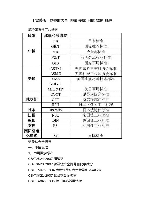
(完整版)钛标准大全-国标-美标-日标-德标-俄标部分国家钛工业标准钛及钛合金标准一、中国标准1、中国国家标准GB/T2524-2007 海绵钛GB/T3620-2007 钛及钛合金牌号和化学成分GB/T15073-1994 铸造钛及钛合金牌号和化学成分GB/T3621-2007 钛及钛合金板材GB/T14845-1993 板式换热器用钛板GB/T3622-1999 钛及钛合金带、箔材GB/T3623-2007 钛及钛合金丝材GB/T3624-2007 钛及钛合金管材GB/T3625-2007 换热器及冷凝器用钛及钛合金管GB/T2965-2007 钛及钛合金棒材GB/T16598-1996 钛及钛合金饼和环GB/T8546-1987 钛-不锈钢复合板GB/T8547-1987 钛-钢复合板GB/T6614-1994 钛及钛合金铸件GB/T5168-1985 两相钛合金高低倍组织检验方法GB/T6611-2008 钛及钛合金术语GB/T8755-2008 钛及钛合金术语金相图谱GB/T12769-2003 钛-铜复合棒GB/T13810-2007 外科植入物用钛及钛合金加工材GB/T12417-1990 外科金属植入物通用技术条件GB/T4698.1-4698.25-1996 海绵钛、钛及钛合金化学分析方法GB/T5193-2007 钛及钛合金加工产品超声波探伤方法GB/T12969.1-1991钛及钛合金管材超声波检验方法GB/T12969.2-1991 钛及钛合金管材涡流检验方法GB/T13149-1991 钛及钛合金符合钢板焊接技术条件GB/T6887-1986 烧结钛金属过滤元件和材料GB/T8180-2007 钛及钛合金加工产品的包装、标志、运输和贮存GB/T6612-1986 重要用途的TA7钛合金板材GB/T6613-1986 重要用途的TC4钛合金板材GB/T1216-1992 TA5钛合金焊接技术条件2、中国国家军用标准GJB2218-1994 航空用钛及钛合金棒材和锻坯规范GJB2219-1994 紧固件用钛及钛合金棒(线)规范GJB2220-1994 航空发动机用钛合金饼、环坯规范GJB2505-1995 航空用钛及钛合金板、带材规范GJB2744-1996 航空用钛及钛合金棒材和自由锻件和模锻件规范GJB2896-1996 钛及钛合金熔模精密铸件规范GJB2921-1997 超塑成形用TC4钛合金板材规范GJB3763A-2004 钛及钛合金热处理GJB391-1987 航天工业用TC4钛合金锻制饼材GJB493-1988 航空发动机叶片用TC4钛合金棒材GJB494-1988 航空发动机叶片用TC11钛合金棒材GJB495-1988 超低温用TA7-D钛合金棒材GJB943-1900 潜艇用TA5-A钛合金锻件GJB944-1900 TA5-A钛合金板材GJB1169-1991 航天用钛合金环材规范GJB1205-1991 TB2-1钛合金铆钉技术条件GJB1538-1992 飞机结构件用TC4钛合金棒材规范二、美国标准1、美国试验与材料协会标准ASTM B229-2001 海绵钛ASTM B265-2005 钛及钛合金带、薄板及板ASTM B337-1995 钛及钛合金无缝管和焊接管(已被B861-2002 钛及钛合金无缝管、B862-2002钛及钛合金焊接管代替)ASTM B338-2005a 钛及钛合金冷凝器和热交换器用无缝管和焊接管ASTM B348-2005 钛及钛合金棒和坯料ASTM B363-2004 非合金钛及钛合金无缝和焊接管件ASTM B367-2004 钛及钛合金铸件ASTM B861-2002 钛及钛合金无缝管ASTM B862-2002 钛及钛合金焊接管ASTM B381-2005 钛及钛合金锻件ASTM F67-2000 外科植入物用纯钛材ASTM F136-2002a 外科植入物用Ti-6Al-4V ELI加工材ASTM F620-2002 外科植入物用α+β相钛合金锻件ASTM F1108-2002 外科植入物用Ti-6Al-4V铸件ASTM F1295-2001 外科植入物用Ti-6Al-7Nb加工材ASTM F1341-1999 纯钛丝材ASTM F1472-2002a 外科植入物用Ti-6Al-4V加工材ASTM F1713-1996 外科植入物用Ti-13Nb-13Zr加工材ASTM F1813-2001 外科植入物用Ti-12Mo-6Zr-2Fe加工材ASTM F2063-2000 医疗器械和外科植入物用形状记忆合金加工材2、美国机械工程师协会标准ASME 第八部分:第一章压力容器(基本规则)美国宇航材料技术标准AMS 4900-2001 钛薄板、带和板材(退火状态)(380Mpa)AMS4901-2002 钛薄板、带和板材(退火状态)(485Mpa)AMS4902-2001 钛薄板、带和板材(退火状态)(275Mpa)AMS4907-2001 超低间隙元素级Ti-6Al-4V合金薄板、带和板材(退火状态)AMS4910-2003 Ti-5Al-2.5Sn合金薄板、带和中厚板(退火状态)AMS4911-2003 Ti-6Al-4V薄板、带和中厚板(退火状态)AMS4921-2004 钛的棒材、锻件和环件(退火状态)(485Mpa)AMS4924-2002 超低间隙元素级Ti-5Al-2.5Sn合金棒、锻件和环件(退火状态)AMS4926-2001 Ti-5Al-2.5Sn棒和环形件(退火状态)(760Mpa)AMS4928-2001 Ti-6Al-4V合金棒、锻件和环件(退火状态)(825Mpa)AMS4941-2003 钛焊管AMS4942-2001 无缝钛管(退火状态)(275Mpa)AMS4930-2001 超低间隙元素级Ti-6Al-4V合金棒材、锻件和环件(退火状态)AMS4951-2003 工业纯钛焊丝AMS4954-2003 Ti-6Al-4V合金焊丝AMS4965-2002 Ti-6Al-4V合金棒、锻件和环件(固溶和稳定化处理)AMS4966-2003 Ti-5Al-2.5Sn锻件AMS4967-2001 可热处理的Ti-6Al-4V合金棒、锻件和环件(退火状态)ASM4972-2003 Ti-8Al-1Mo-1V合金棒和环件(固溶和稳定化处理)ASM4973-2002 Ti-8Al-1Mo-1V钛合金锻件(固溶和稳定化处理)ASM4975-2003 Ti-6Al-2Sn-4Zr-2Mo合金棒和环件(固溶和稳定化处理)ASM4983-2002 Ti-10V-2F-3Al锻件(固溶处理和时效)ASM4985-2003 石蜡或石墨捣实法铸造的Ti-6Al-4V合金锻件ASM4991-2002 Ti-6Al-4V合金精锻件(退火状态)ASM2380-2003 优质钛合金认可和控制3、美国军用标准MIL-T-9046-1999 钛及钛合金薄板、带材和板材MIL-T-9047-2005 钛及钛合金棒材和锻坯MIL-R-81588-1986 钛及钛合金圆棒和丝MIL-F-83142-2000 钛及钛合金锻件(优质级)MIL-T-46077 钛合金可焊的装甲厚板MIL-T-13405 钛粉末MIL-T-46035-1989 高强度钛合金、变形材料MIL-T-81556-1996 钛及钛合金的圆棒、棒材、特殊形状面的挤压件MIL-T-81200 钛及钛合金的热处理三、英国标准BS2TA1:1974 工业纯钛的薄板和带(抗拉强度290-420Mpa)BS2TA2:1973 工业纯钛的薄板和带(抗拉强度390-540Mpa)BS2TA3:1973 机加工用的工业纯钛棒材和型材(抗拉强度390-540Mpa)BS2TA4:1973 工业纯钛的锻坯(抗拉强度390-540Mpa)BS2TA5:1973 工业纯钛的锻坯(抗拉强度390-540Mpa)BS2TA6:1973 工业纯钛的薄板和带(抗拉强度570-730Mpa)BS2TA7:1973 机加工用的工业纯钛棒材和型材(抗拉强度540-740Mpa)BS2TA8:1973 工业纯钛的锻坯(抗拉强度540-740Mpa)BS2TA9:1973 工业纯钛的锻件(抗拉强度540-740Mpa)BS2TA10:1974 钛-铝-钒合金的薄板和带材(抗拉强度960-1270Mpa)BS2TA11:1974 机加工用钛-铝-钒合金棒材和型材(抗拉强度900-1160Mpa)BS2TA12:1974 钛-铝-钒合金锻坯(抗拉强度900-1160Mpa)BS2TA13:1974 钛-铝-钒合金锻件(抗拉强度900-1160Mpa)BS2TA21:1973 钛-铜合金的薄板和带材(抗拉强度540-770Mpa)BS2TA22:1973 机加工用的钛-铜合金棒材和型材(抗拉强度540-770Mpa)BS2TA23:1973 钛-铜合金的锻坯(抗拉强度540-770Mpa)BS2TA24:1973 钛-铜合金的锻件(抗拉强度540-770Mpa)BS2TA28:1974 钛-铝-钒合金锻坯和丝材(抗拉强度1100-1300Mpa)BSTA38:1993 机加工用的钛-铝-钼-锡-硅-碳合金的棒材(抗拉强度1250-1420Mpa)BSTA39:1993 钛-铝-钼-锡-硅-碳合金的锻坯(抗拉强度1250-1420Mpa)BSTA40:1993 机加工用的钛-铝-钼-锡-硅-碳合金的棒材(抗拉强度1250-1375Mpa)BSTA41:1993 钛-铝-钼-锡-硅-碳合金的锻坯(抗拉强度1250-1375Mpa)BSTA42:1993 钛-铝-钼-锡-硅-碳合金的锻件(抗拉强度1250-1375Mpa)BSTA45:1993 机加工用的钛-铝-钼-锡-硅合金的棒材和型材(抗拉强度1100-1280Mpa)BSTA46:1993 机加工用的钛-铝-钼-锡-硅合金的棒材和型材(抗拉强度1050-1220Mpa)BSTA47:1993 钛-铝-钼-锡-硅合金的锻坯(抗拉强度1050-1220Mpa)BSTA48:1993 钛-铝-钼-锡-硅合金的锻坯(抗拉强度1050-1220Mpa)BSTA49:1993 机加工用的钛-铝-钼-锡-硅合金的棒材和型材(抗拉强度1000-1200Mpa)BSTA50:1993 钛-铝-钼-锡-硅合金的锻坯(抗拉强度1000-1200Mpa)BSTA51:1993 钛-铝-钼-锡-硅合金的锻件(抗拉强度1000-1200Mpa)BSTA52:1993 钛-铜合金的薄板和带材(抗拉强度690-920Mpa)BSTA56:1993 钛-铝-钒合金的厚板(抗拉强度895-1150Mpa)BSTA57:1993 钛-铝-钼-锡-硅的厚板(抗拉强度1030-1220Mpa)BSTA58:1993 钛-铜合金的厚板(抗拉强度520-640Mpa)BSTA100:1973 变形钛及钛合金的检验和实验方法BS5500:1997 无焰熔化焊压力容器CP3003 压力容器的衬里和化工用设备四、俄罗斯标准ΓOCT17746-79 海绵钛ΓOCT19807-91 变形钛及钛合金牌号ΓOCT22178-90 钛及钛合金薄板ΓOCT23755-87 钛及钛合金厚板ΓOCT21945-82 热轧无缝钛管ΓOCT22897-86 冷轧无缝钛管ΓOCT24890-81 焊接钛管ΓOCT26492-85 钛及钛合金轧棒ΓOCT27265-87 钛及钛合金填充丝说明书五、日本标准JISH2151-1983 海绵钛JISH4600-1993 钛及钛合金板和带JISH4630-1994 钛及钛合金无缝管JISH4631-1994 钛及钛合金热交换器用管JISH4635-1994 钛及钛合金焊接管JISH4650-2000 钛及钛合金棒JISH4657-1998 钛及钛合金锻件JISH4670-1993 钛及钛合金丝JIS7505 钛铸件六、德国标准DIN17850-1990 工业纯钛压力加工材的化学成分DIN17851-1990 钛合金压力加工材的化学成分DIN17860-1990 钛及钛合金板和带DIN17861-1990 钛及钛合金无缝管DIN17862-1990 钛及钛合金棒DIN17863-1973 钛及钛合金丝材DIN17864-1993 钛及钛合金锻件DIN17865-1990 铸钛DIN17866-1990 钛及钛合金焊接管DIN1737T1-1984 钛及钛钯合金填充材料的化学成分、技术条件DIN1737T2-1988 钛及钛钯合金填充材料全焊金属的试块、试样、力学与工艺性能DIN931 外六角螺栓半螺纹DIN933 外六角螺栓全螺纹DIN931 外六角螺母DIN125 普通垫片DIN127 弹簧垫片七、法国标准NFL21-110 1975 纯钛T40锻造用棒坯NFL21-270 1981 TA6V铆钉丝用杆材NFL14-601 1984 TA6V锻造用棒材NFL14-602 1984 TA6V锻件NFL14-603 1984 TA6V锻造用棒坯NFL14-604 1984 TA6V锻件NFL14-611 1984 TA6VZr5D棒坯NFL14-612 1984 TA6VZr5D锻件八、ISO国际标准(外科植入物用钛的标准)ISO5832-2-1999 纯钛ISO5832-3-1996 Ti-6Al-4V加工材ISO5832-11-1994 Ti-6Al-7Nb加工材。
ta18钛合金管 国外标准

ta18钛合金管国外标准全文共四篇示例,供读者参考第一篇示例:TA18钛合金管是一种采用TA18钛合金材料制成的管材,具有良好的机械性能和耐腐蚀性能。
TA18钛合金管的国外标准主要有ASTM、AMS等标准,这些标准规定了TA18钛合金管的化学成分、力学性能、热处理工艺等重要技术要求,保证了TA18钛合金管的质量和可靠性。
TA18钛合金管的国外标准还规定了其热处理工艺。
热处理是钛合金材料获得良好性能的重要工艺之一。
根据ASTM标准,TA18钛合金管的热处理工艺应符合特定的要求,包括热处理温度、保温时间等。
通过热处理工艺,可以改善TA18钛合金管的晶粒结构,提高其强度和硬度,延长其使用寿命。
TA18钛合金管的国外标准是保障其质量和可靠性的重要依据。
遵循国外标准生产的TA18钛合金管具有优异的机械性能和耐腐蚀性能,能够满足各种工程应用的要求。
随着钛合金材料在工业领域中的广泛应用,TA18钛合金管将在航空航天、船舶制造、医疗器械等领域发挥重要作用,为社会经济的发展做出贡献。
希望随着技术的不断创新和进步,TA18钛合金管的质量能够得到进一步提升,为人类社会的可持续发展提供有力支持。
第二篇示例:ta18钛合金管是一种高强度、耐腐蚀的钛合金材料,广泛应用于航空航天、化工、医疗等领域。
ta18钛合金管在国外的标准制定和应用方面非常严格,主要参考国际标准组织(ISO)和美国标准协会(ANSI)制定的标准。
本文将详细介绍关于ta18钛合金管的国外标准。
ta18钛合金管的国外标准主要包括以下几个方面:1. 化学成分:ta18钛合金管的化学成分是制定国外标准的重要依据之一。
其主要元素包括钛(Ti)、铝(Al)、钒(V)、铁(Fe)等。
根据ISO和ANSI的标准,ta18钛合金管的化学成分需要符合严格的要求,以保证其性能和质量。
2. 机械性能:ta18钛合金管的机械性能是衡量其质量的重要指标之一。
国外标准通常对ta18钛合金管的抗拉强度、屈服强度、延伸率、硬度等性能指标有详细的规定,以确保其符合使用要求。
国内及国外钛及钛合金标准
国内及国外钛及钛合金标准国内及国外钛及钛合金标准序号标准名称标准号代替标号1 海绵钛ASTM B299-20082 外科植入物用钛及钛合金加工材ASTM F67:20063 钛及钛合金网篮YS/T 577-20064 工业流体用钛及钛合金管YS/T 576-20065 冷凝器和热交换器用无缝和焊接钛及钛合金管ASTM B338:2010 ASTM B338:19997 无缝和焊接钛及钛合金管ASTM B337:1995a8 钛及钛合金线材ASTMB863:19999 钛及钛合金标准焊接管ASTMB862:2009 ASTMB862:199910 钛及钛合金标准无缝管ASTMB861:2010 ASTMB861:199911 钛及钛合金锻件ASTMB381:2010 ASTMB381:200912 钛及钛合金铸件ASTMB367:199313 无缝和焊接纯钛及钛合金焊接配件ASTMB363:2006a ASTMB363:199914 钛及钛合金棒和坯锭ASTMB348:2010 ASTMB348:199515 冷凝器和热交换器用无缝和焊接钛及钛合金管ASTMB338:19991 钛及钛合金牌号和化学成分GB/T 3620.1-2007 GB/T 3620.1-19942 钛及钛合金加工产品化学成分允许偏差GB/T 3620.2-2007 GB/T 3620.2-19943 钛及钛合金饼和环GB/T 16598-19964 外科植入物用钛及钛合金加工材GB/T 13810-2007 GB/T 13810-19975 钛及钛合金铸锭GB/T 26060-20106 钛及钛合金铸件GB/T 6614-1994 GB/T 6614-19867 换热器及冷凝器用钛及钛合金管GB/T 3625-2007 GB/T 3625-19958 钛及钛合金无缝管GB/T 3624-2010 GB 3624-19959 钛及钛合金焊接管GB/T 26057-201010 钛及钛合金挤压管GB/T 26058-201011 钛及钛合金丝GB/T 3623-2007 GB/T 3623-199812 钛及钛合金带、箔材GB/T 3622-1999 GB 3622-198313 钛及钛合金板材GB/T 3621-2007 GB/T 3621-199414 板式换热器用钛板GB/T 14845-2007 GB/T 14845-199315 钛及钛合金网板GB/T 26059-201016 钛及钛合金棒材GB/T 2965-2007 GB/T 2965-199617 钛铜复合棒GB/T 12769-2003 GB/T 12769-199118 钛钢复合板GB/T 8547-2006 GB/T 8547-198719 钛-不锈钢复合板GB/T 8546-200720 航天用钛合金环材规范GJB 1169-199121 紧固件用钛及钛合金棒(线)材规范GJB 2219-1994。
国家标准《紧固件用钛及钛合金棒材和丝材》(讨论稿)编制说明

紧固件用钛及钛合金棒材和丝材(GB/T XXXXX -XXXX)编制说明(讨论稿)2021-06《紧固件用钛及钛合金棒材和丝材》编制说明(讨论稿)一、工作简况(一)任务来源根据国家标准化管理委员会《关于下达2020年第二批推荐性国家标准计划的通知》(国标委发〔2020〕37号)要求,国家标准《紧固件用钛及钛合金棒材和丝材》制定项目由全国有色金属标准化技术委员会归口,项目计划编号:20202822-T-610,项目周期为24个月,计划完成年限为2022年7月,标准项目由宝钛集团有限公司、宝鸡钛业股份有限公司、有色金属技术经济研究院有限责任公司等单位负责起草。
(二)主要参加单位和工作组成员及其所作的工作2.1 主要参加单位情况标准主编单位宝钛集团有限公司在标准的编制过程中,能积极主动收集国内外相关标准,负责项目的总体实施和策划,能够带领编制组成员单位认真细致修改标准文本,征求多家企业的修改意见,编制实测数据统计表,公司能够带领编制组成员单位认真细致修改标准文本,征求多家企业的修改意见,最终带领编制组完成标准的编制工作。
宝鸡钛业股份有限公司、有色金属技术经济研究院有限责任公司等单位积极参加标准调研工作,针对标准的讨论稿和征求意见稿提出修改意见,主要负责标准中术语的编写和把关。
2.2 主要工作成员所负责的工作情况本标准主要起草人及工作职责见表1。
(三)工作过程1. 预研阶段2019年1月至2020年1月,由宝钛集团有限公司及宝鸡钛业股份有限公司对国内紧固件用钛及钛合金棒材和丝材现状调研,同时收集相关国内外实物并做对比,在实物对比和标准现状分析的基础上,起草《紧固件用钛及钛合金棒材和丝材》标准项目建议书、标准草案及标准立项说明等材料。
2. 立项阶段2020年4月,宝钛集团有限公司向全体委员提交了《紧固件用钛及钛合金棒材和丝材》标准项目建议书、标准草案及标准立项说明等材料,全体委员会议论证结论为同意行业标准立项。
(国际贸易)工业纯钛及TAV钛合金棒材加工贸易单耗标准

(国际贸易)工业纯钛及TAV 钛合金棒材加工贸易单耗标准附件4HDB/YS009-2005 工业纯钛及Ti-6Al-4V钛合金棒材加工贸易单耗标准(商品编号81089010)1范围本标准规定了以海绵钛(商品编号81082010)为原料加工生产工业纯钛及Ti-6Al-4V合金棒材(商品编号81089010)的加工贸易单耗标准。
本标准适用于海关和商务主管部门对以海绵钛加工工业纯钛及Ti-6Al-4V钛合金棒材的加工贸易企业进行加工贸易单耗审批、备案和核销管理。
2定义本标准采用以下定义:单耗:指正常生产条件下,生产每单位质量的工业纯钛及Ti-6Al-4V合金棒材所耗用海绵钛的质量单位数。
3单耗标准3.1原料品质规格本单耗标准中的海绵钛应符合ГОСТ17746、ASTMB299、JISH2151、GB/T2524、协议标准等采购合同签订的任壹标准或组合。
3.2成品品质规格本单耗标准中的工业纯钛及Ti-6Al-4V钛合金棒材应符合AMS、ASM、ASTM、JIS、协议标准等合同签订的任壹标准或组合。
3.3单耗标准工业纯钛及Ti-6Al-4V钛合金棒材加工贸易单耗标准HDB/YS009-2005工业纯钛及Ti-6Al-4V钛合金棒材加工贸易单耗标准编制说明1任务来源为加强加工贸易单耗管理,规范和完善海关和商务管理部门对加工贸易单耗的审批、备案、核销,打击伪报单耗的不法行为,促进加工贸易的健康发展,根据海关总暑办公厅、原国家经贸委办公厅关于下发2002年海关系统加工贸易单耗标准制定任务的通知,特制定工业纯钛及Ti-6Al-4V钛合金棒材加工贸易单耗标准。
本标准由海关总署办公厅、原国家经贸委办公厅委托西安海关负责起草制定。
由海关总署加贸司、国家发展改革委经贸司和中国有色金属工业协会组织关联工业协会及企业的工艺、技术专家和海关加工贸易保税专业技术人员组成的评审委员会进行审定。
2制定单耗标准的原则单耗标准制定原则是以国家标准、行业标准和该行业加工贸易企业的平均生产水平为制定基础,贯彻国家税收政策、产业政策和外贸政策,符合我国加工贸易企业的生产实际,有利于加工贸易企业技术进步和公平竞争,便于海关有效监管和关联单耗数据信息的使用和维护。
国内及国外钛及钛合金标准

7
无缝和焊接钛及钛合金管
ASTM B337:1995a
8
钛及钛合金线材
ASTMB863:1999
9
钛及钛合金标准焊接管
ASTMB862:2009
ASTMB862:1999
10
钛及钛合金标准无缝管
ASTMB861:2010
ASTMB861:1999
11
钛及钛合金锻件
ASTMB381:2010
国内及国外钛及钛合金标准
序号
标准名称
标准号
代替标号
1
海绵钛
ASTM B299-2008
2
外科植入物用钛及钛合金加工材
ASTM F67:2006
3
钛及钛合金网篮
YS/T 577-2006
4
工业流体用钛及钛合金管
YS/T 576-2006
5
冷凝器和热交换器用无缝和焊接钛及钛合金管
ASTM B338:2010
1
钛及钛合金牌号和化学成分
GB/T 3620.1-2007
GB/T 3620.1-1994
2
钛及钛合金加工产品化学成分允许偏差
GB/T 3620.2-2007
GB/T 3620.2-1994
3
钛及钛合金饼和环
GB/T 16598-1996
4
外科植入物用钛及钛合金加工材
GB/T 13810-2007
GB/T 13810-1997
钛-不锈钢复合板
GB/T 8546-2007
20
航天用钛合金环材规范
GJB 1169-1991
21
紧固件用钛及钛合金棒(线)材规范
GJB 2219-1994
低中压锅炉用无缝钢管标准

低中压锅炉用无缝钢管标准
低中压锅炉用无缝钢管的标准根据不同的国家和地区可能有所不同。
以下是一些常见的低中压锅炉用无缝钢管标准:
1. GB/T3087-2008 《低中压锅炉用无缝钢管》 (中华人民共和
国标准)
2. ASTM A192/A192M-17 《标准规范for高压无缝碳钢锅炉管》(美国标准)
3. DIN 17175 《钢及特种钢无缝圆截面锅炉管》 (德国标准)
4. JIS G3461 《碳素钢管特殊要求用于锅炉和热交换器管》
(日本工业标准)
5. BS 3059-2 《钢及锅炉和热交换器使用的碳素、合金无缝管》(英国标准)
6. EN 10216-2 《无缝钢管用于压力设备》 (欧洲标准)
7. ASME SA-106 《无缝碳钢管适用于高温服务》 (美国机械工程师学会标准)
这些标准通常规定了低中压锅炉用无缝钢管的化学成分、机械性能、尺寸、制造方法、检验要求等方面的技术要求。
在选择和采购低中压锅炉用无缝钢管时,需要根据具体的使用要求和地区的标准要求来确定使用的标准。
最新无缝钢管执行标准
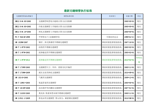
最新无缝钢管执行标准
管件执行标准之美国标准:标准号描述
ASME/ANSI B16.9 工厂制造的锻钢对焊管件
ASME/ANSI B16.11 承插焊和螺纹锻造管件
ASME/ANSI B16.28 钢制对焊小半径弯头和回头弯
ASME B16.5 管法兰和法兰配件
MSS SP-43 锻制不锈钢对焊管件
MSS SP-83 承插焊和螺纹活接头
MSS SP-97 承插焊、螺纹和对焊端的整体加强式管座
管件执行标准之电力标准:标准号描述
GD87-1101 火电发电厂汽水管道零件及部件典型设计手册
DL/T515 电站弯管
管件执行标准之化工标准:标准号描述
HGJ514 碳钢、低合金钢无缝对焊管件
HGJ528 钢制有缝对焊管件
HGJ10 锻钢制承插焊管件
HGJ529 锻钢制承插焊、螺纹和对焊接管台
HGJ-44-76-91 钢制管法兰、垫片、紧固件
HG20592-20635 钢制管法兰、垫片、紧固件
管件执行标准之中石化标准标准号描述
SH3406 石油化工钢制管法兰
SH3408 钢制对焊无缝管件
SH3409 锻钢制承插焊管件
SH3410 钢板制对焊管件
管件执行标准之国家标准:标准号描述
GB12459 钢制对焊无缝管件
GB/T13401 钢板制对焊管件
GB/T14383 锻钢制承插焊管件
GB9112-9131 钢制管法兰、法兰盖及法兰用垫片
管件执行标准之中石油标准:标准号描述
SY/T0510-1998 钢制对焊管件
SY5257-91 钢制弯管。
- 1、下载文档前请自行甄别文档内容的完整性,平台不提供额外的编辑、内容补充、找答案等附加服务。
- 2、"仅部分预览"的文档,不可在线预览部分如存在完整性等问题,可反馈申请退款(可完整预览的文档不适用该条件!)。
- 3、如文档侵犯您的权益,请联系客服反馈,我们会尽快为您处理(人工客服工作时间:9:00-18:30)。
SAE Technical Standards Board Rules provide that: “This report is published by SAE to advance the state of technical and engineering sciences. The use of this report is entirely voluntary, and its applicability and suitability for any particular use, including any patent infringement arising therefrom, is the sole responsibility of the user.”SAE reviews each technical report at least every five years at which time it may be reaffirmed, revised, or cancelled. SAE invites your written comments and suggestions. Copyright © 2006 SAE InternationalAll rights reserved. No part of this publication may be reproduced, stored in a retrieval system or transmitted, in any form or by any means, electronic, mechanical, photocopying, recording, or otherwise, without the prior written permission of SAE. TO PLACE A DOCUMENT ORDER: Tel: 877-606-7323 (inside USA and Canada) Tel: 724-776-4970 (outside USA) Fax: 724-776-0790Email: CustomerService@ SAE WEB ADDRESS:h ttp://AMS 4946BAEROSPACE MATERIALSPECIFICATIONIssued OCT 2002 Revised MAY 2006 Superseding AMS 4946ATitanium Alloy Tubing, Seamless, Hydraulic3Al - 2.5V, Texture Controlled Cold Worked, Stress Relieved(Composition similar to UNS R56320)RATIONALEAMS 4946B is a review and update including a revision to the upper limit for Contractile Strain Ratio. 1. SCOPE 1.1 FormThis specification covers a titanium alloy in the form of seamless tubing. 1.2 ApplicationThis tubing has been used typically for parts, such as hydraulic lines, requiring strength and oxidation resistance up to600 °F (316 °C), and weldability, but usage is not limited to such applications. 1.3 TypesThis specification covers the following types: 1.3.1Type I - Tubing with 105 ksi (724 MPa) minimum yield strengthType II - Tubing with 95 ksi (655 MPa) minimum yield strength Type III - Tubing with 70 ksi (433 MPa) minimum yield strength 2. APPLICABLE DOCUMENTSThe issue of the following documents in effect on the date of the purchase order forms a part of this specification to the extent specified herein. The supplier may work to a subsequent revision of a document unless a specific document issue is specified. When the referenced document has been cancelled and no superseding document has been specified, the last published issue of that document shall apply.2.1 SAE PublicationsAvailable from SAE International, 400 Commonwealth Drive, Warrendale, PA 15096-0001, Tel: 877-606-7323 (inside USA and Canada) or 724-776-4970 (outside USA), or . AMS 2244 Tolerances, Titanium and Titanium Alloy TubingAMS 2249 Chemical Check Analysis Limits, Titanium and Titanium Alloy AMS 2634 Ultrasonic Inspection, Thin Wall Metal Tubing AMS 2750 PyrometryAMS 2809 Identification, Titanium and Titanium Alloy Wrought Products AMS-H-81200 Heat Treatment of Titanium and Titanium AlloysAS4076 Contractile Strain Ratio Testing of Titanium Hydraulic Tubing AS33611Tube Bend Radii2.2 ASTM PublicationsAvailable from ASTM International, 100 Barr Harbor Drive, P.O. Box C700, West Conshohocken, PA 19428-2959, Tel: 610-832-9585, or . ASTM E 8 Tension Testing of Metallic MaterialsASTM E 1409 Determination of Oxygen and Nitrogen in Titanium and Titanium Alloys by the Inert Gas Fusion TechniqueASTM E 1447 Determination of Hydrogen in Titanium and Titanium Alloys by the Inert Gas Fusion Thermal Conductivity/Infrared Detection MethodASTM E 1941 Standard Test Method for Determination of Carbon in Refractory and Reactive Metals and Their AlloysASTM E 2371Standard Test Method for Analysis of Titanium and Titanium Alloys by Atomic Emission Plasma Spectrometry2.3 ASME PublicationsAvailable from American Society of Mechanical Engineers, 22 Law Drive, P.O. Box 2900, Fairfield, NJ 07007-2900, Tel: 973-882-1170, or . ASME B46.1Surface Texture3. TECHNICAL REQUIREMENTS 3.1 CompositionShall conform to the percentages by weight shown in Table 1; carbon shall be determined in accordance with ASTM E 1941, hydrogen in accordance with ASTM E 1447, oxygen and nitrogen in accordance with ASTM E 1409, and other elements in accordance with ASTM E 2371. Other analytical methods may be used if acceptable to the purchaser.TABLE 1 - COMPOSITIONElement min max Aluminum 2.50 3.50 Vanadium 2.00 3.00 Iron -- 0.30 Oxygen -- 0.12 Carbon -- 0.05 Nitrogen -- 0.020 (200 ppm)Hydrogen -- 0.015 (150 ppm)Yttrium (3.1.1) -- 0.005 ( 50 ppm)Other Elements, each (3.1.1) -- 0.10 Other Elements, total (3.1.1) -- 0.40Titanium remainder--`````,,``,`,`,,`,,`,,`,``,```-`-`,,`,,`,`,,`---3.1.1Determination not required for routine acceptance.3.1.2 Check AnalysisComposition variations shall meet the applicable requirements of AMS 2249. 3.2 Melting PracticeAlloy shall be multiple melted; the final melting cycle shall be under vacuum. The first melt shall be made by vacuum consumable electrode, nonconsumable electrode, electron beam cold hearth, or plasma arc cold hearth melting practice. The subsequent melt or melts shall be made under vacuum using vacuum arc remelting (VAR) practice with no alloy additions permitted.3.2.1 The atmosphere for nonconsumable electrode melting shall be vacuum or shall be argon and/or helium at anabsolute pressure not higher than 1000 mm of mercury. 3.2.2The electrode tip for nonconsumable electrode melting shall be water-cooled copper.3.3 ConditionCold worked and stress relieved by heating to a temperature not lower than 700 °F (371 °C) and holding at heat for not less than 30 minutes. Tubing which is rotary straightened after final reduction shall be stress relieved at a minimum temperature of 700 °F for not less than two hours after straightening.3.3.1 Heat treating equipment shall conform to the requirements of AMS-H-81200. Furnaces shall meet therequirements of AMS 2750 for Type A furnaces. Uniformity shall be between ±25 °F (±14 °C) with a readability requirement of ±2° (±1°). 3.4 PropertiesTubing shall conform to the following requirements: 3.4.1 Tensile PropertiesShall be as shown in Table 2, determined in accordance with ASTM E 8 with the rate of strain maintained at 0.003 to 0.007 inch/inch/minute (0.003 to 0.007 mm/mm/minute) through the yield strength and then increased so as to produce failure in approximately one additional minute. When a dispute occurs between purchaser and vendor over the yield strength values, a referee test shall be performed on a machine having a strain rate pacer, using a rate of 0.005 inch/inch/minute (0.005 mm/mm/minute) through the yield strength, and a minimum cross head speed of 0.10 inch (2.5 mm) per minute above the yield strength.TABLE 2 - TENSILE VALUESType Property ValueI Tensile Strength 125 to 142 ksi (862 to 979 MPa) Yield Strength at 0.2% Offset 105 ksi (724 MPa) Minimum Elongation in 2 Inches (50.4 mm) Nom. Dia. Up to 0.250 inch (6.35 mm), incl 10% Minimum Nom. Dia. Over 0.250 inch (6.35 mm) 14% Minimum II Tensile Strength 100 to 133 ksi (690 to 917 MPa) Yield Strength at 0.2% Offset 95 ksi (655 MPa) Minimum Elongation in 1 inch (6.35 mm) 13% Minimum III Tensile Strength 85 to 102 ksi (586 to 703 MPa) Yield Strength at 0.2% Offset 70 ksi (483 MPa) Minimum Elongation in 2 inches (50.8 mm) 15% Minimum--`````,,``,`,`,,`,,`,,`,``,```-`-`,,`,,`,`,,`---3.4.2 FlarabilitySpecimens as in 4.3.3 shall withstand flaring at room temperature, without formation of cracks or other visible defects when examined at 10X magnification, by being forced axially, with a steady pressure, over a hardened and polished tapered steel pin having a 74-degree included angle to produce a flare having a permanent expanded OD not less than 1.20 times the original nominal OD for Types I and II, and not less than 1.30 times the original nominal OD for Type III. 3.4.3 Pressure TestingTubing shall show no bulges, leaks, pin holes, cracks, or other defects when subjected to an internal hydrostatic pressure (P) sufficient to cause a tensile stress equivalent to the minimum rated yield strength in the tubing wall, except that a diametric permanent set of 0.002 inch/inch (0.002 mm/mm) of diameter is acceptable. The hydrostatic pressure (P) shallbe determined from Equation 1:where:P = Test pressure in ksi (MPa)S = Minimum Yield Strength in ksi (MPa) D = Nominal OD d = Nominal ID 3.4.4 BendingTubing shall not develop cracks, tears, breaks, or other flaws when bent 180 degrees around a suitable bend die having a centerline radius equal to three times the nominal OD of the tubing. A solid rotary ball-type retractable mandrel inserted to the tangent of the bend shall be used to support the inside of the tube during bending to restrict flattening to a value that does not exceed 3% of the nominal OD of the tube. Flatness shall be measured in accordance with AS33611. 3.4.5 FlatteningThe inside and outside surfaces of tubing shall show no cracks, tears, breaks, opened die marks, or opened polishing marks when a full section of the tube (minimum 2 inches (51 mm) long) is flattened between parallel plates under a load applied gradually and perpendicularly to the longitudinal axis until the distance between the plates is not greater than the flattening factors shown in Table 3. After examination of the outside surfaces, the samples shall be split longitudinally and the inside surfaces examined. Examination of tube surfaces shall be at 5 to 10X magnification. Additional standards may be agreed upon by purchaser and vendor for any tube sizes not listed in Table 3.TABLE 3 - FLATTENING TEST-INCH/POUND UNITSNominal Tube Outer Diameter Inch NominalTube Wall Thickness Inch Material Type Distance Between Plates Wheret = Actual Wall Thickness 0.250 0.016 Type I 12t 0.250 0.016 Type II 9t 0.250 0.018 Type I 10t 0.250 0.020 Type I 10t 0.250 0.022 Type II 8t 0.250 0.022 Type I 10t 0.250 0.028 Type I 9t 0.250 0.028 Type III 6t 0.313 0.020 Type I 12t 0.375 0.019 Type I 11t 0.375 0.020 Type I 13t 0.375 0.022 Type I 13t 0.375 0.028 Type I 10t--`````,,``,`,`,,`,,`,,`,``,```-`-`,,`,,`,`,,`---TABLE 3 - FLATTENING TEST-INCH/POUND UNITS (CONTINUED)Nominal Tube Outer Diameter Inch NominalTube Wall Thickness Inch Material Type Distance Between Plates Wheret = Actual Wall Thickness 0.375 0.032 Type I 9t 0.375 0.038 Type I 9t 0.375 0.042 Type I 8t 0.500 0.020 Type I 14t 0.500 0.022 Type I 14t 0.500 0.026 Type I 13t 0.500 0.035 Type I 10t 0.500 0.042 Type I 9t 0.500 0.043 Type I 9t 0.500 0.051 Type I 8t 0.500 0.056 Type I 8t 0.625 0.020 Type I 16t 0.625 0.023 Type I 15t 0.625 0.027 Type I 14t 0.625 0.032 Type I 13t 0.625 0.035 Type I 12t 0.625 0.044 Type I 10t 0.625 0.052 Type I 9t 0.625 0.054 Type I 9t 0.625 0.071 Type I 8t 0.750 0.020 Type I 17t 0.750 0.027 Type I 15t 0.750 0.039 Type I 12t 0.750 0.049 Type I 10t 0.750 0.052 Type I 10t 0.750 0.063 Type I 9t 0.750 0.065 Type I 9t 0.875 0.020 Type I 19t 0.875 0.032 Type I 14t 0.875 0.045 Type I 12t 0.875 0.050 Type I 11t 0.875 0.061 Type I 10t 1.000 0.020 Type I 20t 1.000 0.021 Type I 19t 1.000 0.028 Type I 17t 1.000 0.030 Type I 16t 1.000 0.035 Type I 15t 1.000 0.036 Type I 14t 1.000 0.051 Type I 12t 1.000 0.070 Type I 10t 1.000 0.088 Type I 9t 1.000 0.140 Type I 8t 1.250 0.026 Type I 19t 1.250 0.028 Type I 18t 1.250 0.045 Type I 14t 1.250 0.046 Type I 14t 1.250 0.065 Type I 12t 1.250 0.070 Type I 12t 1.250 0.087 Type I 11t 1.500 0.032 Type I 18t 1.500 0.049 Type I 15t 1.500 0.054 Type I 14t3.4.6 MicrostructureType I and Type II shall be predominantly an elongated wrought structure but some areas of partially transformed beta structure shall be acceptable. Type III shall be equiaxed wrought structure but some areas of partially transformed beta will be acceptable. Standards shall be acceptable to purchaser unless standards for acceptance are specified by purchaser. Tubing shall be free of any oxygen-rich layer, such as alpha case (See 8.2), or other surface contamination, determined by microscopic examination at not lower than 400X magnification or by other method agreed upon by purchaser and vendor.3.4.7 Contractile Strain RatioThe contractile strain ratio (CSR) for Types I and II tubing, when tested in accordance with AS4076, shall be between 1.3 and 3.5 for the tubing sizes with wall thicknesses indicated in Table 4. The CSR for tubing sizes indicated in Table 5, shall be between 1.5 and 3.5. Additional standards for acceptance may be agreed upon by purchaser and vendor for any tube sizes not listed.TABLE 4 - TUBING SIZES FOR 1.3 - 3.5 CONTRACTILE STRAIN RATIONominal OD Inches Nominal ODMillimetersWall ThicknessInchWall ThicknessMillimeters3/16 4.8 0.020 max 0.51 max1/4 6.4 0.022 max 0.56 max3/8 9.5 0.032 max 0.81 max1/2 12.7 0.043 max 1.09 max5/8 15.9 0.054 max 1.37 max3/4 19.0 0.065 max 1.65 max7/8 22.2 0.077 max 1.96 max1 25.4 0.088 max 2.24 max1-1/4 31.8 0.071 and larger 18.1 and larger 1-1/2 38.1 0.066 and larger 1.68 and larger TABLE 5 - TUBING SIZES FOR 1.5 - 3.5 CONTRACTILE STRAIN RATIONominal OD Inches Nominal ODMillimetersWall ThicknessInchWall ThicknessMillimeters1-1/4 31.8 0.070 1.781-1/2 38.1 0.065 1.653.5 QualityTubing, as received by purchaser, shall be uniform in appearance, quality, and condition, for all lengths of tubing within that lot, and shall have a finish conforming to the best practice for high quality aircraft tubing. It shall be smooth and free from scale or oxide, burrs, seams, tears, grooves, laminations, slivers, pits, and other imperfections detrimental to usage of the tubing. Surface imperfections, such as handling marks or straightening marks, will not be considered injurious if the imperfections are removable within the tolerances specified for wall thickness but removal of such imperfections is not required.3.5.1 Each tube shall be ultrasonically inspected in accordance with AMS 2634, Class AA, for ID, OD, and subsurfaceimperfections of all types and orientations (longitudinal and transverse).3.5.2 SurfaceCondition3.5.2.1 ODSurfaceShall show a uniformly acid-pickled surface finish; not less than 0.001 inch (0.025 mm) shall have been chemically removed from the wall thickness as a finishing operation. Soft belt polishing prior to the pickling operation is permissible; traces of the polishing marks may remain after the pickling operation. Centerless grinding or other mechanical operations are not permitted.3.5.2.2 IDSurfaceShall show a uniform matte finish, produced by abrasive blasting with grit not larger than 100 mesh (150 µm), followed by forced-flow acid pickling to remove not less than 0.0005 inch (0.013 mm) from the wall thickness.3.5.2.3 SurfaceTextureShall be not greater than 63 microinches (1.6 µm) on the ID and 32 microinches (0.8 µm) on the OD, determined in accordance with ASME B46.1.3.5.2.4 The ID and OD surfaces of the tubing shall be free from grease and other foreign matter. Metallic flakes orparticles shall not be collected by a clean, white cloth drawn through the length of the bore of a test sample.Discoloration of the cloth, without the presence of flakes or particles, is acceptable.3.6 TolerancesShall conform to all applicable requirements of the following:3.6.1 OuterDiameterShall be as specified in Table 6; tolerances shown include ovality.TABLE 6A - TOLERANCES, OUTER DIAMETER, INCH/POUND UNITSNominal OD Inches ToleranceInchesPlusToleranceInchesMinus0.093to0.187,incl 0.002 0.000 Over 0.187 to 0.499, incl 0.003 0.000 Over 0.499 to 0.749, incl 0.004 0.000 Over 0.749 to 0.999, incl 0.004 0.001 Over 0.999 to 1.499, incl 0.004 0.002 Over 1.499 to 1.999, incl 0.005 0.002TABLE 6B - TOLERANCES, OUTER DIAMETER, SI UNITSNominal ID Millimeters ToleranceMillimetersPlusToleranceMillimetersMinus2.36to 4.75,incl 0.05 0.00 Over 4.75to 12.67,incl 0.08 0.00 Over12.67to 19.02,incl 0.10 0.00 Over19.02to 25.37,incl 0.10 0.025 Over25.37to 38.07,incl 0.10 0.05 Over38.07to 50.77,incl 0.13 0.05 --` ` ` ` ` , , ` ` , ` , ` , , ` , , ` , , ` , ` ` , ` ` ` -` -` , , ` , , ` , ` , , ` ---3.6.2 Inner DiameterShall be as specified in Table 7. The nominal inner diameter is defined as being equal to the nominal OD minus twice the nominal wall thickness.TABLE 7A - TOLERANCES, INNER DIAMETER, INCH/POUND UNITSNominal ID Inches Tolerance Inch Plus ToleranceInch MinusUp to 0.338,incl 0.0015 0.0015Over 0.338to 0.449,incl 0.002 0.002 Over 0.449to 0.673,incl 0.0025 0.0025 Over 0.673to 0.900,incl 0.003 0.003Over 0.900and above0.004 0.004 TABLE 7B - TOLERANCES, INNER DIAMETER, SI UNITS Nominal ID Millimeters Tolerance Millimeters Plus ToleranceMillimeters MinusUp to 8.59,incl 0.038 0.038Over 8.59to 11.40,incl 0.05 0.05 Over 11.40to 17.09,incl 0.064 0.064 Over 17.09to 22.86,incl 0.08 0.08Over 22.86and above0.10 0.10 3.6.3 Wall ThicknessAll tubing 1.500 inches (38.10 mm) and under in nominal OD shall have a wall thickness not less than 95% of nominal. 3.6.4Length and StraightnessShall conform to AMS 2244.4. QUALITY ASSURANCE PROVISIONS 4.1Responsibility for InspectionThe vendor of tubing shall supply all samples for vendor's tests and shall be responsible for the performance of allrequired tests. Purchaser reserves the right to sample and to perform any confirmatory testing deemed necessary to ensure that the tubing conforms to specified requirements. 4.2Classification of Tests4.2.1 Acceptance TestsAll technical requirements except pressure testing (3.4.3) are acceptance tests and shall be performed on each heat or lot as applicable.4.2.2 Periodic TestsPressure testing (3.4.3) is a periodic test and shall be performed at a frequency selected by the vendor unless frequency of testing is specified by purchaser.--`````,,``,`,`,,`,,`,,`,``,```-`-`,,`,,`,`,,`---4.2.3 Preproduction TestsAll technical requirements are preproduction tests and shall be performed prior to or on the initial shipment of tubing to a purchaser, when a change in material and/or processing requires reapproval as in 4.4.2, and when purchaser deems confirmatory testing to be required. 4.3Sampling and TestingA lot shall be all tubing of the same nominal size from the same ingot, same processing and finishing operations, and stress relieved in the same furnace charge: 4.3.1 CompositionOne sample from each heat, except that for hydrogen determinations one sample from each lot obtained after thermal and chemical processing is completed. An ingot analysis obtained from the alloy producer may be utilized to substantiate heat requirements.4.3.2 Tensile PropertiesOne sample for each 1000 feet (305 m) or three samples from each lot, whichever is greater. Tensile testing shall include a minimum of one specimen obtained from the middle and each end of the furnace used to stress relieve the tube lot. 4.3.3 FlarabilityOne sample per tube for lot sizes of four or less tubes and four samples for lot sizes of 5 to 39 tubes. For lot sizes of 40 or more tubes, one sample from one end of 10% of the tubes shall be tested. 4.3.3.1Specimens for flarability (3.4.2) test shall be full tubes or sections cut from a tube. The end of the specimen to be flared shall be cut square, with the cut end smooth and free from burrs, but not rounded.4.3.4 Pressure TestSpecimen length shall be 9 inches (229 mm) minimum. Test with a pressure as determined in paragraph 3.4.3 for a minimum of two minutes. 4.3.5 BendingTwo specimens from each lot. 4.3.6 FlatteningThree samples minimum and ten samples maximum. One sample is required for each 135 feet (41 m) of tubing. Specimens of the full section of the tube not less than two inches in length shall be cut from separate tubes. 4.3.7 Microstructure One sample from each lot.4.3.8 Contractile Strain Ratio (CSR)Three specimens per lot. 4.3.9 Ultrasonic Inspection Each tube.--`````,,``,`,`,,`,,`,,`,``,```-`-`,,`,,`,`,,`---4.3.10 Surface ConditionEach tube, except that ID surface inspection need be made only on each sample selected for the flattening test. 4.3.10.1 Tolerances Each tube. 4.4 Approval4.4.1 Sample tubing, and process sheets showing the parameters for the process control factors for producing thetubing, shall be approved by purchaser before tubing for production use is supplied, unless such approval is waived by purchaser. 4.4.2 Vendor shall establish parameters for the process control factors that will produce tubing meeting the technicalrequirements of this specification. If necessary to make any change in parameters for the process control factors, vendor shall submit for reapproval revised process sheets and, when requested, sample tubing. Tubing incorporating the revised operations shall not be shipped prior to receipt of reapproval. 4.4.2.1Control factors for producing tubing include, but are not limited to, the following:Source of supply and acceptance criteria for tube hollows Conditioning practice for tube hollowsTube reduction steps – Number of steps and reduction schedule Cold working proceduresMandrel placement and mandrel surface integrityIntermediate tube annealing, conditioning, and inspection procedures Heat treatment parameters and pyrometry proceduresTube ID and OD finishing operations, including etching proceduresInspection methods and procedures including ultrasonic inspection technique and visual examination for surface condition4.4.2.1.1Any of the above process control factors for which parameters are considered proprietary by the vendor may be assigned a code designation. Each variation in such parameters shall be assigned a modified code designation.4.5 ReportsThe vendor of tubing shall furnish with each shipment a report showing the results of tests for chemical composition of each heat and for the hydrogen content, tensile properties, flarability, bending, flattening, microstructure, and contractile strain ratio of each lot, and stating that the tubing conforms to the other technical requirements. This report shall include the purchase order number, heat and lot numbers, AMS 4946B size, and quantity.4.6 Resampling and RetestingIf any specimen used in the above tests fails to meet the specified requirements, disposition of the tubing may be based on the results of testing three additional specimens, from tubes not tested in the original sampling, for each original nonconforming specimen. Except as in 4.6.1, failure of any retest specimen to meet the specified requirements shall be cause for rejection of the tubing represented. Results of all tests shall be reported. 4.6.1The resampling for contractile strain ratio (CSR) test failures shall be done using three samples from the same tube. The average of the three retest results and the initial result shall meet the CSR requirement.--`````,,``,`,`,,`,,`,,`,``,```-`-`,,`,,`,`,,`---SAE AMS 4946B - 11 -5. PREPARATION FOR DELIVERY 5.1 IdentificationIdentification shall be in accordance with AMS 2809. 5.2 Packaging5.2.1 A lot of tubing may be packaged in small quantities and delivered under the basic lot approval provided lotidentification is maintained. 5.2.2Tubing shall be prepared for shipment in accordance with commercial practice and in compliance with applicable rules and regulations pertaining to the handling, packaging, and transportation of the tubing to ensure carrier acceptance and safe delivery.6. ACKNOWLEDGMENTA vendor shall mention this specification number and its revision letter in all quotations and when acknowledging purchase orders. 7. REJECTIONSTubing not conforming to this specification, or to modifications authorized by purchaser, will be subject to rejection. 8. NOTES8.1 A change bar (|) located in the left margin is for the convenience of the user in locating areas where technicalrevisions, not editorial changes, have been made to the previous issue of this specification. An (R) symbol to the left of the document title indicates a complete revision of the specification, including technical revisions. Change bars and (R) are not used in original publications, nor in specifications that contain editorial changes only. 8.2An oxygen-rich layer, such as alpha case, is hard and brittle and results in marked lowering of fatigue properties.8.3 This tubing is fabricated in a manner so as to optimize and control its crystallographic texture for high fatiguestrength and for consistency in production bending. 8.4Terms used in AMS are clarified in ARP1917.8.5 Dimensions and properties in inch/pound units and the Fahrenheit temperatures are primary; dimensions andproperties in SI units and the Celsius temperatures are shown as the approximate equivalents of the primary units and are presented only for information. 8.6Purchase documents should specify not less than the following:AMS 4946BAS5620 when desired (See 8.7) Size of tubing desired Quantity of tubing desired Type of tubingStandards for acceptance of microstructure (See 3.4.6).8.7 AS5620 should be included in the purchase document when additional qualification testing (Hydraulic ImpulseTesting/S-N Curves), a Qualified Manufacturer Listing (QML), and a Qualified Products Listing (QPL) are desired.PREPARED BY AMS COMMITTEE "G"--`````,,``,`,`,,`,,`,,`,``,```-`-`,,`,,`,`,,`---。