GP2S60B中文资料
6260 1.0 HP 合成材料直径锯机说明书
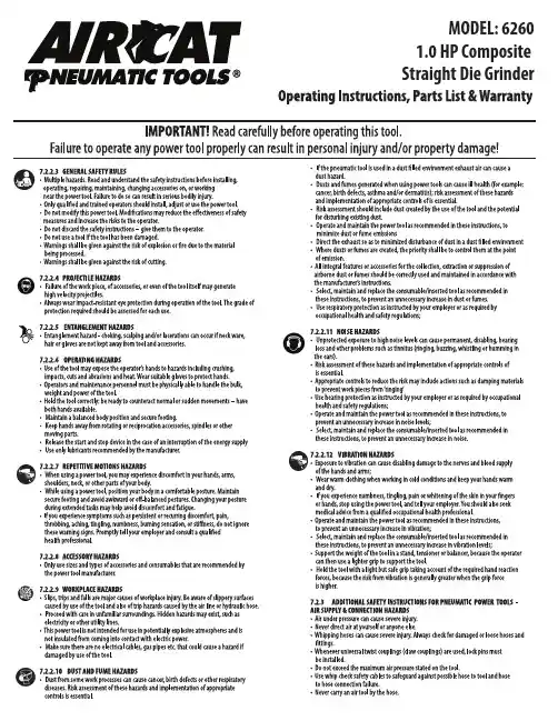
6260
22,000
1.0
1/4
Gears Direct Drive
Exhaust Rear
Weight Length Air Cons. (lbs.) (in) (CFM)
1.2
9.25
8
Rec. Hose Size
(in.)
3/8
Air Inlet (in.)
1/4
Air Supply
Tools of this class operate on a wide range of air pressure. It is recommended that air pressure of these tools measures 90 PSI at the tool while running free. Higher pressure and unclean air will shorten the tool’s life because of faster wear and may create a hazardous condition and void the warranty. Water in the air line will cause damage to the tool. Drain the air tank daily. Clean the air inlet lter screen on at least a weekly schedule. The recommended hookup procedure can be viewed in the illustration below. The air inlet, used for connecting air supply, has standard 1/4” NPT American Thread or BSP British Standard Pipethread. Line pressure should be increased to compensate for unusually long air hoses (over 25 feet). Minimum hose diameter should be 3/8 I.D. and ttings should have the same inside dimensions.
BD7620KS2资料
(Contact address for overseas customers in Japan)
Yokohama
As of 18th. As
No technical content pages of this document may be reproduced in any form or transmitted by any means without prior permission of ROHM CO.,LTD. The contents described herein are subject to change without notice. The specifications for the product described in this document are for reference only. Upon actual use, therefore, please request that specifications to be separately delivered. Application circuit diagrams and circuit constants contained herein are shown as examples of standard use and operation. Please pay careful attention to the peripheral conditions when designing circuits and deciding upon circuit constants in the set. Any data, including, but not limited to application circuit diagrams information, described herein are intended only as illustrations of such devices and not as the specifications for such devices. ROHM CO.,LTD. disclaims any warranty that any use of such devices shall be free from infringement of any third party's intellectual property rights or other proprietary rights, and further, assumes no liability of whatsoever nature in the event of any such infringement, or arising from or connected with or related to the use of such devices. Upon the sale of any such devices, other than for buyer's right to use such devices itself, resell or otherwise dispose of the same, no express or implied right or license to practice or commercially exploit any intellectual property rights or other proprietary rights owned or controlled by ROHM CO., LTD. is granted to any such buyer. Products listed in this document are no antiradiation design.
GP2Y0A710K0F中文资料
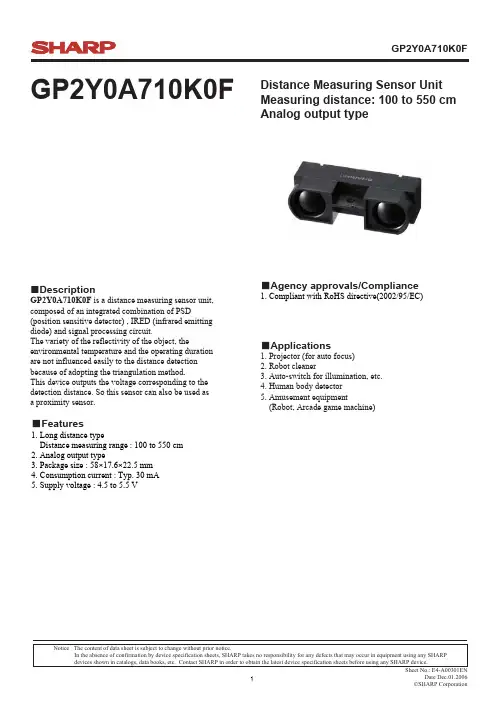
GP2Y0A710K0FGP2Y0A710K0FDistance Measuring Sensor Unit Measuring distance: 100 to 550 cm Analog output type■Applications1. Projector (for auto focus)2. Robot cleaner3. Auto-switch for illumination, etc.4. Human body detector5. Amusement equipment(Robot, Arcade game machine)■Features1. Long distance typeDistance measuring range : 100 to 550 cm 2. Analog output type3. Package size : 58×17.6×22.5 mm4. Consumption current : Typ. 30 mA5. Supply voltage : 4.5 to 5.5 V■Agency approvals/Compliance1. Compliant with RoHS directive(2002/95/EC)Notice The content of data sheet is subject to change without prior notice.In the absence of confirmation by device specification sheets, SHARP takes no responsibility for any defects that may occur in equipment using any SHARP ■DescriptionGP2Y0A710K0F is a distance measuring sensor unit,composed of an integrated combination of PSD(position sensitive detector) , IRED (infrared emitting diode) and signal processing circuit.The variety of the reflectivity of the object, theenvironmental temperature and the operating duration are not influenced easily to the distance detection because of adopting the triangulation method.This device outputs the voltage corresponding to the detection distance. So this sensor can also be used asa proximity sensor.■Block diagram■Outline Dimensions(Unit : mm)Product mass : approx. 9gSignalprocessing circuitPSDLEDDistance measuring ICVoltage regulatorOscillation circuitOutput circuitLED drive circuit④V O①⑤GND②③V CCTerminalSymbol ①GroundGND ②Supply voltage V CC ③Supply voltageV CC ④Output terminal voltage V O ⑤GroundGNDNote 1. Unspecified tolerances shall be ± 0.3mm.Note 2. The connector is made by J.S.T.TRADING COMPANY,LTD. and its part number is B5B-ZR.Note 3. The dimensions in parenthesis are shown for reference.Stamp (Example)Model nameProduction year : Last digit of prod. yearProduction month : Jan. to Sep. ; 1 to 9, Oct. ; X, Nov. ; Y , Dec. ; Z Light detector sideLight emitter sidePin numberStamp⑤④③②①(T a =25℃,V CC =5V)ParameterSymbol ConditionsRating Unit Supply voltageV CC4.5 to5.5V■Absolute Maximum Ratings(T a =25℃,V CC =5V)■Electro-optical Characteristics* L : Distance to reflective objectNote 1 : Using reflective object : White paper (Made by Kodak Co., Ltd. gray cards R-27・white face, reflectance; 90%)Note 2 : The value at 550 cm is the average of 20 times distance measuring.Symbol Rating Unit Supply voltageV CC -0.3 to +7V Output terminal voltage V O -0.3 to V CC +0.3V Operating temperature T opr -10 to +60℃Storage temperatureT stg-40 to +70℃ParameterParameterSymbol Conditions MIN.TYP.MAX.Unit Average supply current I CC L=150cm (Note 1)―3050mA Distance measuring ΔL (Note 1)100―550cm Output voltageV O L=100cm (Note 1)2.3 2.5 2.7V VΔV O10.50.7Output voltage differential0.9V Output voltage difference between L=100cm and L=200cm (Note 1)ΔV O2Output voltage difference (L=100cm →200cm)/Output voltage differentce (L=200cm →550cm)(Note 1,2)1.251.551.85■Recommended operating conditionsFig. 1 Timing chartVcc(Power supply)nth outputnthmeasurementSecondmeasurementFirst measurementSecond outputFirst output Unstable output MAX 5.0ms16.5ms±3.7msDistance measuring operatingVo(Output)Fig. 2 Example of distance measuring characteristics(output)00.511.522.533.50100200300400500Distance L (cm)O u t p u t V o l t a g e (V )White paper Gray paper00.511.522.533.500.0020.0040.0060.0080.01Inverse number of distance 1/L (1/cm)O u t p u t v o l t a g e (V )White paper Gray paperNote. Reflection : White paper (reflectance : 90%) : Gray paper (reflectance: 18%)■Notes●Advice for the optics• The lens of this device needs to be kept clean. There are cases that dust, water or oil and so on deteriorate the characteristics of this device. Please consider in actual application.• Please don’t do washing. Washing may deteriorate the characteristics of optical system and so on.Please confirm resistance to chemicals under the actual usage since this product has not been designed against washing.●Advice for the characteristics• In case that an optical filter is set in front of the emitter and detector portion, the optical filter which has the most efficient transmittance at the emitting wavelength range of LED for this product (λ = 870 ± 70nm), shall berecommended to use. Both faces of the filter should be mirror polishing. Also, as there are cases that the characteristics may not be satisfied according to the distance between the protection cover and this product or the thickness of the protection cover, please use this product after confirming the operation sufficiently in actual application.• In case that there is an object near to emitter side of the sensor between sensor and a detecting object, please use this device after confirming sufficiently that the characteristics of this sensor do not change by the object.• When the detector is exposed to the direct light from the sun, tungsten lamp and so on, there are cases that it can not measure the distance exactly. Please consider the design that the detector is not exposed to the direct light from such light source.• Distance to a mirror reflector can not be sometimes measured exactly.In case of changing the mounting angle of this product, it may measure the distance exactly.• In case that reflective object has boundary line which material or color etc. are excessively different, in order todecrease deviation of measuring distance, it shall be recommended to set the sensor that the direction of boundary line and the line between emitter center and detector center are in parallel.• In order to decrease deviation of measuring distance by moving direction of the reflective object, it shall be recommended to set the sensor that the moving direction of the object and the line between emitter center and detector center are vertical.●Advice for the power supply• In order to stabilize power supply line, we recommend to insert a by-pass capacitor of 10μF or more between Vcc and GND near this product.• Please use power supply which can output 350mA or more to operate this product properly since this product requires about330mA as the sensing peak current to LED.(Incorrect)(Correct)(Incorrect)(Moving direction)(Correct)(Moving direction)●Notes on handling• There are some possibilities that the internal components in the sensor may be exposed to the excessive mechanical stress. Please be careful not to cause any excessive pressure on the sensor package and also on the PCB while assembling this product.●Presence of ODC etc.This product shall not contain the following materials.And they are not used in the production process for this product.Regulation substances : CFCs, Halon, Carbon tetrachloride, 1.1.1-Trichloroethane (Methylchloroform) Specific brominated flame retardants such as the PBB and PBDE are not used in this product at all.This product shall not contain the following materials banned in the RoHS Directive (2002/95/EC).• Lead, Mercury, Cadmium, Hexavalent chromium, Polybrominated biphenyls (PBB),Polybrominated diphenyl ethers (PBDE).■Package specificationPackage methodMAX.50 pieces per trayMAX 500 pieces per caseArranges in 10 stages of trays containing products into the outer case.Put pads between trays.Closes the lid of case and seals with kraft tape.Package compositionPadProductTrayPacking caseProductTray section■Important Notices· The circuit application examples in this publication are provided to explain representative applications of SHARP devices and are not intended to guarantee any circuit design or license any intellectual property rights. SHARP takes no responsibility for any problems related to any intellectual property right of a third party resulting from the use of SHARP's devices.· Contact SHARP in order to obtain the latest device specifi-cation sheets before using any SHARP device. SHARP reserves the right to make changes in the specifications, characteristics, data, materials, structure, and other contents described herein at any time without notice in order to improve design or reliability. Manufacturing locations are also subject to change without notice.· Observe the following points when using any devices in this publication. SHARP takes no responsibility for damage caused by improper use of the devices which does not meet the conditions and absolute maximum ratings to be used specified in the relevant specification sheet nor meet the following condi-tions:(i) The devices in this publication are designed for use in general electronic equipment designs such as:--- Personal computers--- Office automation equipment--- Telecommunication equipment [terminal]--- Test and measurement equipment--- Industrial control--- Audio visual equipment--- Consumer electronics(ii) Measures such as fail-safe function and redundant design should be taken to ensure reliability and safety when SHARP devices are used for or in connection with equipment that requires higher reliability such as:--- Transportation control and safety equipment (i.e.,aircraft, trains, automobiles, etc.)--- Traffic signals--- Gas leakage sensor breakers--- Alarm equipment--- Various safety devices, etc.(iii) SHARP devices shall not be used for or in connection with equipment that requires an extremely high level of reliability and safety such as:--- Space applications--- Telecommunication equipment [trunk lines]--- Nuclear power control equipment--- Medical and other life support equipment (e.g.,scuba).· If the SHARP devices listed in this publication fall within the scope of strategic products described in the Foreign Exchange and Foreign Trade Law of Japan, it is necessary to obtain approval to export such SHARP devices.· This publication is the proprietary product of SHARP and is copyrighted, with all rights reserved. Under the copy-right laws, no part of this publication may be repro-duced or transmitted in any form or by any means, electronic or mechanical, for any purpose, in whole or in part, without the express written permission of SHARP. Express written permission is also required before any use of this publication may be made by a third party.· Contact and consult with a SHARP representative if there are any questions about the contents of this publication.。
GP2数据采集器用户手册说明书
GP2 数据采集器控制器高级数据采集控制器—具备复杂计算测量和高级反馈控制功能用户手册 1.0 版目录目录 (2)开箱 (3)概述 (4)安装 DELTALINK (7)连接至 GP2 (7)帮助信息 (8)6 个步骤轻松创建简单程序 (9)GP2 模拟器 (10)程序示例 (11)检查传感器工作状态和开始记录 (11)取回、查看和保存记录的数据 (11)数据集导入向导 (11)附录 1:GP2 继电器扩展模块 (12)附录 2:GP2 网络布线 (16)附录 3:扩展外壳 (20)附录 4:WS-CAN 外盖 (22)附录 5:DL-MKT 通用数据数据采集器安装套件 (23)附录 6:M-ENCL-B2 机壳 (24)附录 7:确保 GP2 正确密封 (25)GP2 规格 (26)产品保养与维护 (34)GP2 校准证书 (34)法律和法规信息 (34)索引 (35)GP2 包装内容:GP2 数据采集器(带 6AA 电池,需由用户安装)GP2-USB GP2 专用 USB 线缆DVD光盘,内含 DeltaLINK 3 软件、视频教程和文档GP2 用户手册螺丝刀和线缆防水接头扳手可选配件GP2 有 12 个差分模拟输入通道2、四个事件/数字计数器通道和一个 WET 传感器串行输入通道。
使用继电器扩展模块,可将两个输出继电器扩展为 6 个。
两组端子为传感器提供 3V 精密基准电源或非稳压电源。
还有一个 5V 和一个12V 电源端子。
每个传感器可按从 1 秒至 >1000 天的不同频率读取。
任意测量组合可有多种记录频率选择。
提供多种记录类型:平均、最小、最大、总计、累计、风向图、按条件。
数据采集器可保存约 250 万条读数。
每个继电器能控制单独的实验、区域或测试协议,每个都基于不同的阈值设置或逻辑。
使用传感器库和易用的用户界面,您可在 PC 上快速创建简单程序并发送到数据采集器。
还可创建复杂程序脚本,无需学习编程语言或键入任何命令。
WMSP02WMSP06产品技术规格书

WMSP02/WMSP06产品规格书V1.0.1北京联盛德微电子有限责任公司 (winner micro)地址:北京市海淀区上园村3号交大知行大厦七层电话:+86-10-62161900公司网址:文档历史目录1概述 (2)2规范性引用文件 (2)3缩略语 (2)4介绍 (3)5特征 (3)5.1接口 (3)5.2无线 (3)5.3其它 (4)6规格 (4)7天线规格 (5)8接口信号 (6)9环境适应性试验 (8)9.1低温工作试验 (8)9.2低温存储试验 (8)9.3高温工作试验 (8)9.4高温存储试验 (8)9.5温度冲击试验 (9)9.6震动试验 (9)9.7环保认证 (9)1概述本规格书规定了基于嵌入式Wi-Fi SoC W500 的表贴式SPI无线模块的物理特性、技术指标、通信协议、产品功能、性能、稳定性、环境适应性以及安全性等方面的技术标准。
2规范性引用文件《GB 15629.11-2003》《IEEE 802.11-1999》《IEEE 802.11a-1999》《IEEE 802.11b-1999》《IEEE 802.11b-1999_Cor1-2001》《IEEE 802.11d-2001》《IEEE 802.11F-2003》《IEEE 802.11G-2003》《IEEE 802.11h-2003》《IEEE 802.11i-2004》《IEEE 802.11i-2004_Decrypt》3缩略语IBSS:由网卡组建的网络BSS:由AP组建的网络RTS:请求发送控制帧CTS:清除发送控制帧WEP:有线对等加密TKIP:临时密钥完整性协议CCMP:计数模式CBC-MAC协议WPA:Wi-Fi保护接入WPA2:WPA的第2版,在WPA基础上加入了CCMPAP:无线网卡接入点SSID:无线网络名称标识BSSID:区分网络的唯一标识4介绍本产品是基于嵌入式Wi-Fi SoC W500单芯片设计的表贴式SPI无线产品模块,形成新的SPI接口网卡,型号为WMSP02/WMSP06。
GP2U06资料
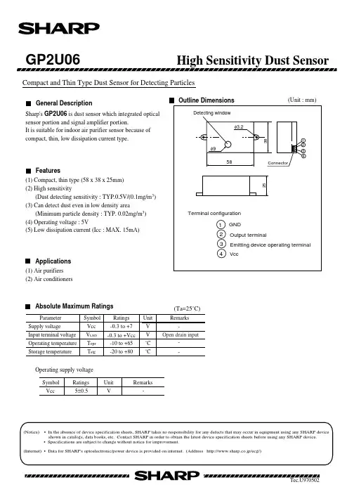
Compact and Thin Type Dust Sensor for Detecting ParticlesSharp's GP2U06 is dust sensor which integrated optical sensor portion and signal amplifier portion.It is suitable for indoor air purifier sensor because of compact, thin, low dissipation current type.(1) Compact, thin type (58 x 38 x 25mm)(2) High sensitivity(Dust detecting sensitivity : TYP.0.5V/(0.1mg/m 3)(3) Can detect dust even in low density area(Minimum particle density : TYP. 0.02mg/m 3)(4) Operating voltage : 5V(5) Low dissipation current (Icc : MAX. 15mA)(1) Air purifiers (2) Air conditionersVVccOperating supply voltage5±0.5Parameter Symbol Ratings Unit Vcc V Input terminal voltage V LED V Operating temperature ˚C Storage temperature˚CRemarks -Supply voltage -0.3 to +7-0.3 to +Vcc -10 to +65-20 to +80T opr T stg(Unit : mm)General DescriptionFeaturesApplications Absolute Maximum Ratings(Ta=25˚C)(Notice) • In the absence of device specification sheets, SHARP takes no responsibility for any defects that may occur in equipment using any SHARP device shown in catalogs, data books, etc. Contact SHARP in order to obtain the latest device specification sheets before using any SHARP device. • Specifications are subject to change without notice for improvement.(Internet) • Data for SHARP's optoelectronic/power device is provided on internet. (Address http://www.sharp.co.jp/ecg/)Symbol Ratings Unit Remarks---Open drain inputGP2U06Input condition to LED terminalRecommended input conditions to LED terminalT=30±5ms PW=0.4±0.1msElectro-optical CharacteristicsBlock Diagram(Ta=25˚C, Vcc=5V)*1 • Dust density is measured by mildseven smoke density, using digital dust meter [P-5L2 made by SHIBATA scientific instrumental industry].• Detecting sensitivity is settled according to the change of output voltage when dust density change 0.1mg/m 3 from the initial value.*2 Input conditions to LED terminal (pulse operation condition) is shown in the right figure.。
COMBOII安装手册(中文版)
COMBOII安装手册(中文版)康宝(Combo II)分体式壁挂一体机操作说明书CODE:27414为了能够充分发挥此紧密型过滤器的作用,请遵照以下的说明使用:1.请查包装内物品COMBO过滤装置的以下所有配件放置在两个包装内。
A)前组件箱(图1)(第50页)a.设备前舱b.设备前整流器c.DIN571 M8*50的螺栓及与相配的栓塞与垫圈两套d.DIN96 M6*40的螺栓及与相配的栓塞与垫圈两套e.橡胶垫两个B)过滤设备箱(图2)f.过滤设备g.设备后整流器h.两个固定后箱的DIN7982 3.9*16的螺栓i.排水管连接口(已安装在过滤设备内部)j.过滤箱排水管k.4个直径为50的排水管接口l.预过滤器盖及水泵钥匙m.水泵使用手册n.DIN 7985 M8*20 的加固顶盖的螺栓两套o.装有4个直径为 50的管子的口袋2.主要特性COMBO这套专为净化泳池水质的而设计的过滤系统是由两个基本部分组成:安装在游泳池壁上的前舱组件和一个包括水泵、过滤器及控制板在内的过滤系统。
这些组件是通过4个管道与1根电缆线而互相连接的。
组件描述(图3、4)(第50页)1.设备前舱组件主体2.设备后整流器3.照明器4.撇沫器进水盖(图1)(第50页)5.撇沫器活动盖6.清洁胶管连接口7.回水槽8.过滤箱主体9.过滤箱上盖10.侧舱保险栓(图2)(第50页)11.水泵12.过滤器13.泳池清洁整流管14.过滤、排水整流管15.配电板16.废水排出口17.水泵排出口18.变压器19.照明器电缆密封管20.气动按钮本套过滤系统可利用一套简单的设备实现以下四个功能:过滤泳池水质为泳池清洁提供接口抽干池水提供泳池照明使用此套集成式过滤设备的优点在于安装简易。
只需一个电源及两个排水管即可,并且符合UNE 20-460-93安装标准。
厂商在任何情况下均不负责设备的安装、调试或非出厂原装电器配件的组装。
3.安装及调试:请按照以下步骤进行:3.1.集成过滤设备前舱的安装将COMBO装置放置在最合适的位置,请牢记安装在与风向相反的方向。
LCB2主板参数
序号中文说明英文说明参考值参数说明基本参数1 总层站数Total Floor * 与电梯桥板相同2 待梯层Homing Floor * 根据合同要求3 系统时间Set Time * 根据合同要求4 开门保持时间Open Door Time 3s 根据客户要求5 开门延长时间Open Delay Time 30s 根据客户要求6 返回待梯层时间Homing Time 60s 根据客户要求7 自动开梯时间Start Time * 根据合同或客户要求8 自动关梯时间Stop Time * 根据合同或客户要求9 称重装置Load Setting YES10 消防返回层Fire Floor * 根据合同要求11 锁梯服务层Parking Floor * 根据合同要求12 输入口电平设置Input Type ON13 输出触点类型Output Type OFF14 层站显示设定Set Indication * 根据合同要求15 停靠层站设定Set Stop Floor * 根据合同要求16 开门延长功能选择Open Delay Able NO17 称重装置输出电压Load Give 10V18 制动器测试选择Break Feedback YES19 贯通厅门门机选择Door Select * 根据合同要求20 多功能输入设置Input Select * 根据合同要求21 多功能输出设置Output Select * 根据合同要求22 层显电梯信息设置Show Mode * 根据合同要求运行参数序号中文说明英文说明参考值参数说明1 电梯额定速度Car Speed * 根据合同2 电机额定转速Motor Speed * 根据合同3 编码器脉冲数Pulse * 根据现场实物4 检修运行速度Insp Speed 0.3 m/s 检修运行时调节5 爬行运行速度Leveing Speed 0.3 m/s 快车运行时调节6 单层运行速度Least Speed 1.0 m/s7 抱闸提前打开时间Break On Time 500 ms8 抱闸释放延时时间Break Off Time 500 ms9 加速度率(斜率)Acceleration b1 0.6m/s^2 快车运行时调节10 减速度率(斜率)Deceleration b2 0.6m/s^2 快车运行时调节11 起动时S时间S Curve P1 0.7m/s^3 快车运行时调节12 加速终了S时间S Curve P2 0.7m/s^3 快车运行时调节13 减速开始时S时间S Curve P3 0.7m/s^3 快车运行时调节14 减速终了时S时间S Curve P4 0.7m/s^3 快车运行时调节15 零速度值设置Zero Speed 5 rpm 快车运行时调节16 平层距离调整Leveing Adj 50mm 快车运行时调节特殊参数序号中文说明英文说明参考值参数说明1 门继电器保持时间Door Run Time 5 s2 恢复出厂值Factory Para NO3 并联功能设定Twins Control 0 并联时设14 群控功能设定Group Control 0 群控时设15 远程监控功能设定Far Monitor 0 有远程监控时设16 贯通门设定Two Door Mode 07 消防功能设定Fire Mode 0 有消防功能时设18 并联梯号Parallel No 0 第一台梯设A第二台设B9 多速方式设定Mulit Speed Mode NO 模拟量给定10 多段速度设定Mulit Speed Give 0 模拟量给定11 换速距离Decel Distance 0 模拟量给定12 运行超时时间设置Over Time 45 s。
FSP250-60GTB中文资料
Input CharacteristicsInput Range: 90~264V AC, Full Range Input Frequency: 47~63HzInput Current:10A (RMS) @115V AC, 5A (RMS) @230V ACInrush Current: 60A Max for 264V AC Cold start Specification••••••••••Temperature Range: Operating 0° C ~ +40° C on fullload; storage & shipping -20° C ~ +65° CHumidity: 90% on operating and 95% on storageDielectric Withstand: Input to frame ground 1800V AC for 1 secondEfficiency: 65% at minimum measured at nominal ACmain voltage and frequency with maximum load on alloutputRise Time: Less than 20msHold-up Time: 16ms minimum at 115V/60Hz and 20ms minimum at 230V/50Hz input voltagePower Good Signal: Power on delay time 100 ms to 500 ms, off delay 1ms minimum (TTL and CMOS compatible) Leakage Current: Not exceed 3.5mAMTBF: 100,000 hours on maximum load at +25° C degree Dimension (WxHxL): 150x86x140mm/5.9”x3.4”x5.5”inchesFeatures• • • • • • • •• • • • Complied with ATX and ATX12V standardActive Power Factor Correction Meeting with EN61000-3-2 High efficiency and reliabilityRemote On/Off functionInternal 12V DC 8cm fan includedNoise Killer (Thermal fan speed control function)Low noise and rippleComplies with FCC part 15 subpart J Class B and CISPR 22 Class BOutput over voltage, short circuit, and over current protection 100% Hi-pot, ATE, and burn-in testedRe-settable power shut downApproved by UL 1950, CSA C22.2 Level 3, TUV EN60950, NEMKO EN60950 (CB Report), CESparkle Power Inc.A Leading Power Supply manufacturerWeb site: FSP250-60GTB (For Pentium 4 and Athlon XP) 250 Watts ATX12V Switching Power SupplyOutput CharacteristicsOutput Voltage Minimum Load MaximumLoadLoadReg.LineReg. Ripple & Noise+3.3V0.3A12.12/20A± 5%± 1%50mV P-P +5V0.1A27/21.8A± 5%± 1%50mV P-P +12V 0.0A13.0A± 5%± 1%120mV P-P -5V 0.0A 0.3A ± 10% ± 2% 120mV P-P -12V0.0A0.8A± 10%± 2%120mV P-P +5Vsb0.0A 2.0 A± 5%± 1%50mV P-P *+5V and +3.3V total output not exceed 175W*When +.3.3V is load on 20A, the +5V maximum load is 21.8A*When +.3.3V is load on 12.12A, the +5V maximum load is 27A*+3.3V, +5V, and +12V total output cannot exceed 230WSparkle Power Inc.Main Office1000 Rock AvenueSan Jose, CA 95131TEL: 408-519-8888FAX: 408-519-9999E-MAIL: info@ Sparkle Power Inc.Los Angeles Office17071 Green DriveCity of Industry, CA 91745TEL: 626-839-7180FAX: 626-839-3395Sparkle Power Inc.Colorado Office1316 Indian Paintbrush LaneLongmont, CO 80503TEL: 303-776-3281FAX: 303-776-7645元器件交易网。
GP2S24中文资料
PhotointerrupterSubminiature 1. Compact and thinGP2S26:Flat lead typeGP2S27:Mini-flat package type 2. Optimum detection distance:0.6 to 0.8mm 3. Visible light cut-off type2. Floppy disk drives3. Various microcomputerized control equip- ments Outline Dimensions(Unit :mm )s Featuress Applications1. Cassette tape recorders, VCRs GP2S24GP2S09GP2S09/GP2S24/GP2S26/GP2S27:Compact DIP long lead type :Compact DIP types Absolute Maximum Ratings(Ta =25˚C )The hatched area more than in the figure below.GP2S26The hatched area more than edges of package as shown in the figure below.GP2S27Soldering areaThe hatched area more than edges of package as shown in the figure below.GP2S09, GP2S241mm ∗2 away from the lower ∗1 Within 5 seconds (Soldering areas for each model are shown below )0.5mm away from the both Parameter Rating Unit InputForward current 50mA Reverse voltage 6V Power dissipation75mW OutputCollector-emitter voltage 35V Emitter-collector voltage 6V Collector current20mA Collector power dissiipation 75mW Total power dissipation 100mW Operating temperature -20 to +85˚C Storage temperature -40 to +100˚C ∗1Soldering temperature260˚CSymbol I F V R V CEO V ECO I C P C P tot T opr T stg T solP edge of package as shown 2.0mm away from the both Soldering area:Soldering area:-25025*********0102030405060025-25020*******P o w e r d i s s i p a t i o n P (m W )501007580100855505101525300010020030040050060070020025-250204060801001205010075246810012Fig. 1 Forward Current vs. Ambient TemperatureF o r w a r d c u r r e n t I F (m A )Ambient temperature T a (˚C )Ambient temperature T a (˚C )F o r w a r d c u r r e n t I F (m A )C o l l e c t o r c u r r e n t I C Forward current I F (mA)C o l l e c t o r c u r r e n t I C (µA )Collector-emitter voltage V CE (V )Ambient temperature T a (˚C )Fig. 3 Forward Current vs. Forward VoltageForward CurrentFig. 2 Power Dissipation vs. Ambient TemperatureAmbient TemperatureFig. 4 Collector Current vs. (µA )R e l a t l v e c o l l e c t o r c u r r e n t I C (%)Fig. 6 Relatlve Collector Current vs.I F =4mA V CE =2VV CE =2V T a =25˚CP totP, P C2525252751005025 00.020.050.010.10.10.20.5 1 25100.20.5125 20 50 1000.111010010000.10.2 1 20.5 5 10 20 501002005001000Input0124580 100406020030248010040602061357Fig. 7 Collector Dark Current vs. Ambient TemperatureC o l l e c t o r d a r k c u r r e n t I (A )Ambient temperature T a (˚C )5 10%%R e l a t i v e c o l l e c t o r c u r r e n t (%)Card moving distance L (mm )Fig.11 Relative Collector Current vs.Fig.10 Relative Collector Current vs.Distance between Sensor and Al Evaporation Glass10-1010-910-810-710-6(GP2S24/GP2S26/GP2S27)d =1mm C E O R e s p o n s e t i m e (µs )R e l a t i v e c o l l e c t o r c u r r e n t (%)V CE =2V Test Circuit for Response TimeV CE =20VV CE =2V I C =100µA T a =25˚C t rt ft dt sI F =4mA V CE =2V T a =25˚CDistance between sensor and Al evaporation glass d (mm )I F =4mA T a =25˚CV CE =2V I C =100µA T a =25˚Ct rt ft dt sCard Moving Distance (1)(GP2S09)R e s p o n s e t i m e (µs )Fig. 8 Response Time vs. Load ResistanceLoad resistance R L (k Ω)Fig. 9 Response Time vs. Load ResistanceLoad resistance R L (k Ω)0---- 80406020Fig.12 Relative Collector Current vs.R e l a t i v e s e n s i t i v i t y (%)R e l a t i v e c o l l e c t o r c u r r e n t (%)Wavelength λ (nm )Test Condition for Distance & Detecting Position V o l t a g e g a i n A V (d B )。
- 1、下载文档前请自行甄别文档内容的完整性,平台不提供额外的编辑、内容补充、找答案等附加服务。
- 2、"仅部分预览"的文档,不可在线预览部分如存在完整性等问题,可反馈申请退款(可完整预览的文档不适用该条件!)。
- 3、如文档侵犯您的权益,请联系客服反馈,我们会尽快为您处理(人工客服工作时间:9:00-18:30)。
NOTICE
q The circuit application examples in this publication are provided to explain representative applications of SHARP devices and are not intended to guarantee any circuit design or license any intellectual property rights. SHARP takes no responsibility for any problems related to any intellectual property right of a third party resulting from the use of SHARP's devices.
q Contact SHARP in order to obtain the latest device specification sheets before using any SHARP device. SHARP reserves the right to make changes in the specifications, characteristics, data, materials, structure, and other contents described herein at any time without notice in order to improve design or reliability. Manufacturing locations are also subject to change without notice.
q Observe the following points when using any devices in this publication. SHARP takes no responsibility for damage caused by improper use of the devices which does not meet the conditions and absolute maximum ratings to be used specified in the relevant specification sheet nor meet the following conditions:
(i)The devices in this publication are designed for use in general electronic equipment designs such as:
--- Personal computers
--- Office automation equipment
--- Telecommunication equipment [terminal]
--- Test and measurement equipment
--- Industrial control
--- Audio visual equipment
--- Consumer electronics
(ii)Measures such as fail-safe function and redundant design should be taken to ensure reliability and safety when SHARP devices are used for or in connection with equipment that requires higher reliability such as:
--- Transportation control and safety equipment (i.e., aircraft, trains, automobiles, etc.)
--- Traffic signals
--- Gas leakage sensor breakers
--- Alarm equipment
--- Various safety devices, etc.
(iii)SHARP devices shall not be used for or in connection with equipment that requires an extremely high level of reliability and safety such as:
--- Space applications
--- Telecommunication equipment [trunk lines]
--- Nuclear power control equipment
--- Medical and other life support equipment (e.g., scuba).
q Contact a SHARP representative in advance when intending to use SHARP devices for any "specific" applications other than those recommended by SHARP or when it is unclear which category mentioned above controls the intended use.
q If the SHARP devices listed in this publication fall within the scope of strategic products described in the Foreign Exchange and Foreign Trade Control Law of Japan, it is necessary to obtain approval to export such SHARP devices. q This publication is the proprietary product of SHARP and is copyrighted, with all rights reserved. Under the copyright laws, no part of this publication may be reproduced or transmitted in any form or by any means, electronic or mechanical, for any purpose, in whole or in part, without the express written permission of SHARP. Express written permission is also required before any use of this publication may be made by a third party.
q Contact and consult with a SHARP representative if there are any questions about the contents of this publication.。
