HH231
Honeywell TR21、TR22、TR23、TR24 壁模块说明书
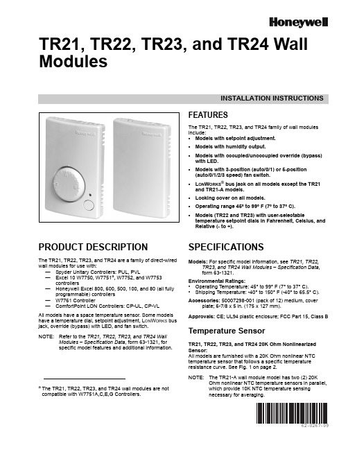
INSTALLATION INSTRUCTIONS62-0267-09TR21, TR22, TR23, and TR24 Wall ModulesFEATURESThe TR21, TR22, TR23, and TR24 family of wall modules include:•Models with setpoint adjustment.•Models with humidity output.•Models with occupied/unoccupied override (bypass) with LED.•Models with 3-position (auto/0/1) or 5-position (auto/0/1/2/3 speed) fan switch.•L ON W ORKS ® bus jack on all models except the TR21 and TR21-A models.•Locking cover on all models.•Operating range 45° to 99° F (7° to 37° C).•Models (TR22 and TR23) with user-selectabletemperature setpoint dials in Fahrenheit, Celsius, and Relative (- to +).PRODUCT DESCRIPTIONThe TR21, TR22, TR23, and TR24 are a family of direct-wired wall modules for use with:—Spyder Unitary Controllers: PUL, PVL—Excel 10 W7750, W7751a , W7752, and W7753controllers—Honeywell Excel 800, 600, 500, 100, and 80 (all fullyprogrammable) controllers —W7761 Controller—ComfortPoint LON Controllers: CP-UL, CP-VL All models have a space temperature sensor. Some models have a temperature dial, setpoint adjustment, L ON W ORKS bus jack, override (bypass) with LED, and fan switch.NOTE:Refer to the TR21, TR22, TR23, and TR24 WallModules – Specification Data , form 63-1321, for specific model features and additional information.SPECIFICATIONSModels: For specific model information, see TR21, TR22,TR23, and TR24 Wall Modules – Specification Data , form 63-1321.Environmental Ratings:•Operating Temperature: 45° to 99° F (7° to 37° C).•Shipping Temperature: -40° to 150° F (-40° to 65.5° C).Accessories: 50007298-001 (pack of 12) medium, coverplate; 6-7/8 x 5in. (175 x 127 mm).Approvals: CE; UL94 plastic enclosure; FCC Part 15, Class BTemperature SensorTR21, TR22, TR23, and TR24 20K Ohm Nonlinearized Sensor:All models are furnished with a 20K Ohm nonlinear NTC temperature sensor that follows a specific temperature resistance curve. See Fig. 1 on page 2.NOTE:The TR21-A wall module model has two (2) 20KOhm nonlinear NTC temperature sensors in parallel, which provide 10K NTC temperature sensingnecessary for averaging.a The TR21, TR22, TR23, and TR24 wall modules are notcompatible with W7751A,C,E,G Controllers.TR21, TR22, TR23, AND TR24 WALL MODULES62-0267—092Fig. 1. Temperature vs. Resistance for Nonlinear Sensor.CommunicationsAll wall modules (except the TR21 and TR21-A models) havea L ON M ARK ® bus communications port. If needed, the jack plug must be removed in the field, and terminals 3 and 4 wired according to the installation instructions.The recommended wire size for the L ON M ARK ® bus is Level IV, 22 AWG (0.34 sq.mm) plenum or non-plenum rated, non-shielded, twisted pair, solid conductor wire.Fig. 2. Wall Module Features (TR23-F Shown).BEFORE INSTALLATIONFailure to follow proper wiring practices canintroduce disruptive electrical interference (noise).Keep wiring at least one foot away from large inductive loads such as motors, line starters, lighting ballasts, and large power distribution panels.Shielded cable is required in installations where these guidelines cannot be met.Ground shild only to grounded controller case.IMPORTANTAll wiring must comply with local electrical codes and ordinances or as specified on installation wiring diagrams.—Wall module wiring can be sized from 16 to 22 AWG (1.31 to 0.33 sq. mm) depending on the application.—The maximum length of wire from a device to a wall module is 1000 ft. (305 m).—Twisted pair wire is recommended for wire runs longer than 100 ft. (30.5 m).INSTALLATIONMount the wall module on an inside wall approximately 54 in. (1372 mm) from the floor (or in the specified location) to allow exposure to the average zone temperature. Do not mount the wall module on an outside wall, on a wall containing water pipes, or near air ducts. Avoid locations that are exposed to discharge air from registers or radiation from lights,appliances, or the sun. See “Cover Disassembly” on page 3.The wall module can be mounted on a wall, on a standard utility conduit box using No. 6 (3.5 mm) screws or on a 60mm wall outlet box (see Fig.3). When mounting directly on a wall, use the type of screws appropriate for the wall material.Fig. 3. Mounting on Standard Utility Conduit Box or60 mm Wall Outlet Box (TR23 Shown).FRONT COVERTR21, TR22, TR23, AND TR24 WALL MODULES362-0267—10Fig. 4. Wall Module Subbase Dimensions in Inches (mm) and Temperature Limit Set Screw Locations (TR23Shown).Cover DisassemblyA snap-fit locking mechanism is used to attach the cover of the wall module to its subbase. To disassemble the cover from the subbase:1.Insert a thin, flat blade screwdriver into each of the twoslots at the bottom of the module to release the two locking tabs. See Fig.2 on page 2.2.Tilt the cover out and away from the subbase to releasethe top two locking tabs.3.To change the dial (e.g. from Fahrenheit to Celsius)release the two tabs on the inside of the front cover and remove the old dial.WiringAttach the wires from the device sensor terminals to the appropriate wall module terminals. See Table 1 on page4.Screw type terminal blocks are designed to accept no more than one 16 AWG (1.31 sq. mm) conductor.Connect multiple wires that are 16-18 AWG(1.31-0.82 sq. mm) with a wire nut. Include a pigtail with this wire group and attach the pigtail to the individual terminal block.Wiring Wall ModulesWire the terminal block as follows:1.For single wires, strip 3/16 in. (5 mm); for multiple wiresgoing into one terminal, strip 1/2 in. (13 mm) insulation from the conductor.2.If two or more wires (20 to 22 AWG only) are beinginserted into one terminal, twist the wires together before inserting. See Fig. 5.3.Insert the wire in the required terminal location and tighten the screw to complete the termination.4.Review and verify the terminal connection wiring and DIP switch settings illustrated in Table 1 on page 4.NOTE:Wire the Lon connection (terminals 3 and 4) usingLevel IV 22 AWG (0.34 mm 2) plenum or non-plenum rated, unshielded, twisted pair, solid conductor wire.Wiring ExamplesTable 1 on page 4 illustrates DIP switch settings and terminal connections for the wall modules. Refer to the TR21, TR22, TR23, and TR24 Wall Modules – Specification Data , form 63-1321, for additional DIP Switch information.IMPORTANTSW 2 on DIP Switch S2 is used for factory calibration of the temperature setpoint potentiometer.Depending on calibration, this switch may be set in either the On or Off position.DO NOT change the position of this switch.NOTES:1.The TR21 and TR22 models do not use DIP Switch S1 and S3.2.DIP Switch S1 is used only on the humidity models, TR21-H and TR23-H.3.Models TR21 and TR21-A use terminals 1 and 2 only. Model TR21-J uses terminals 1, 2, 3, and 4 only.Fig. 5. Attaching Two Wires (20 to 22 AWG) to Wall ModuleTerminals.Attaching the CoverWhen all wiring is complete, attach the cover of the Wall Module as follows:1.Optional : For models with a temperature dial, insert thetwo setpoint screws into the inside of the cover to set the desired temperature range limit. See Fig.4.2.Press the cover straight down onto the subbase until itsnaps into place.3.For models with a temperature dial, insert the desireddial through the opening in the cover. Align the keyed shaft on the knob with the keyed slot into the fitting on the subbase, then press down until it snaps into place.TR21, TR22, TR23, AND TR24 WALL MODULESWiring and DIP switch settings:See Table 1 to determine DIP switch positions and terminal usage for each controller.Table 1. DIP Switch Settings and Terminal Connections.62-0267—094TR21, TR22, TR23, AND TR24 WALL MODULES562-0267—09TR22 and TR23 Setpoint AdjustmentFor the TR22 and TR23 Wall Modules with a setpointadjustment, the controller must be programmed for the values in Table 2 and Table 3.TR23-KL and TR23-H-KLThe TR23-KL and TR23-H-KL ship in packs of 20 and are supplied without setpoint adjustment knobs. Knobs can be ordered separately. See Table 4 for Knob model numbers.Humidity Settings (DIP switch S1)The humidity sensing control mode is set with this 2-position DIP switch. Refer to Fig.4 on page 3 for location of DIP switch S1.NOTE:These switch settings apply only to the TR21-H andTR23-H models.To change the setting, first disconnect the power, then set SW1 and SW2 according to Table 5.TR23 and TR24 Wall Module Override (Bypass) Pushbutton and LED OperationWhen Used With Excel 10 Controllers:The Excel 10 controllers (W7750, W7751, W7752, andW7753) provide timed occupied and unoccupied temperature setpoints for the Wall Module, see Fig. 6. The override pushbutton is used to change the controller into the modes shown in Table 6 and illustrated in Fig.7 on page 6. The override (bypass) LED displays the override status of the controller.Fig. 6. LED and override pushbutton locations(TR23-F Wall Module shown).Table 2. Setpoint Values.Setpoint Value Program Setting55°F (13°C) 2.773 V 65°F (18°C) 2.148 V 75°F (24°C) 1.345 V 85°F (29°C)0.43 VTable 3. Wall Module Setpoint Configuration.Model Setpoint Resistance (Ohms)°F Absolute 55°F 957485°F1426Relative -9°F offset from 70°F 9574+9°F offset from 70°F1426°C Absolute12°C 994530°C1150Table 4. Knob Model NumbersModel DescriptionKNOB-C Celsius scale knob (pack of 20)KNOB-F Fahrenheit scale knob (pack of 20)KNOB-ORelative scale knob (pack of 20)Table 5. DIP Switch S1 Settings.Wall Module Model Sensing Control Individual Switches 12TR21-H TR23-H0-10 Vdc OFF OFF 0-5 Vdc OFF ON 4-20 mAONOFFTR21, TR22, TR23, AND TR24 WALL MODULES62-0267—096Fig. 7. Override pushbutton operation.When Used With Excel 600/500/100/80/50 Controllers:The application engineer/programmer can program theoverride (bypass) and LED to operate in any manner desired. The override (bypass) input is a dry contact, normally open, momentary digital input when the wall module does not have a fan switch. When a fan speed switch (basically a series of resistances based on fan switch position) is present, the override button is an analog input. See Table 4 for resistances.When Used With T7350 Thermostat:TR21, TR21-A, TR21-H, TR22, TR23, and TR24 are the models compatible with the T7350 thermostat. When using with the T7350 thermostat be sure to use the relative +/- offset knob only. The Celsius and Fahrenheit knobs will not work properly with the T7350 Thermostat.TR22-F5, TR23-F3, and TR23-F5 Wall Module Fan SwitchWith the switch in the far left position (Auto), the fanautomatically runs at the speed determined by the controller temperature control algorithm.With the switch in the 0 position, the fan is off. Position 1 is fan speed 1, etc.The wall module fan speed switch overrides the temperature control algorithm.When Used With Excel 10 Controllers:The Excel 10 Controllers (W7750, W7751, W7752, andW7753) can be programmed so that the fan speed switch and override button function the way that the application engineer/programmer wants. See Table 7 for controller-programming resistances. Switch 1 on Dip Switch S2 adds 10k Ohms resistance when OPEN (for Excel 600-80 controllers) and removes it when CLOSED (for Excel 10 controllers).When Used With Excel 600/500/100/80/50 Controllers:Excel 600/500/100/80 Controllers can be programmed so that the fan speed switch and override button function the way that the application engineer/programmer wants. See Table 8 for controller-programming resistances. Switch 1 on Dip Switch S2 adds 10k Ohms resistance when OPEN (for Excel 600-80 controllers) and removes it when CLOSED (for Excel 10 controllers).Table 6. Wall Module Operation.Pushbutton Held Down Controller Model LED Status0 to 1 second No override Off 1 to 4 seconds Timed occupied override On4 to 7 seconds Unoccupied override Single blink per secondLonger than 7 seconds No overrideOffnot applicableContinuous occupied override aaRemote function, which is generated from the network.Two blinks per secondTable 7. Program Settings for Wall Modules withFan Switch using Excel 10 Controllers.For Switch Position Resistance (Ohms)Comment Auto 1861 ±119Left most position 02686 ±127Fan Off position13866 ±13923041 ±13034601 ±146Right most positionOverride button closed Closed circuitTable 8. Program Settings for Wall Modules with Fan Switch using Excel 600/500/100/80 Controllers.For Switch Position Resistance (Ohms)Comment Auto 11.861K ±119Left most position 012.686K ±127Fan Off position113.866K ±139213.04K ±130314.60K ±146Right most positionOverride button closed 10K ±100TR21, TR22, TR23, AND TR24 WALL MODULES 762-0267—09TR21, TR22, TR23, AND TR24 WALL MODULESAutomation and Control Solutions Honeywell International Inc.Honeywell Limited-Honeywell Limitée 1985 Douglas Drive North 35 Dynamic DriveGolden Valley, MN 55422Toronto, Ontario M1V 4Z9® U.S. Registered Trademark© 2009 Honeywell International Inc.62-0267—09E.K. Rev. 09-09L ON W ORKS ® is a registered trademark of Echelon ® Corporation.L ON M ARK ® and the LonMark Logo are trademarks of the LonMark Association.By using this Honeywell literature, you agree that Honeywell will have no liability for any damages arising out of your use or modification to, the literature. You will defend and indemnify Honeywell, its affiliates and subsidiaries, from and against any liability, cost, or damages, including attorneys’ fees, arising out of, or resulting from, any modification to the literature by you.。
MD231 模块 说明书
MD231模块使用手册V0.21简介 (3)1.1. 相关文档 (3)1.2. MD231模块简介 (3)1.3. MD231模块应用简介 (4)2 MD231模块使用 (4)2.1 MD231模块开机 (4)2.2 MD231模块关机 (4)2.3 MD231模块低功耗模式 (5)2.4 MD231模块串口流控 (5)2.5 MD231模块工作的异常处理 (6)3 MD231模块设计建议 (6)3.1 MD231接口板布线建议 (6)1简介本文档帮助客户更好的使用MD231的模块,从软件和硬件的角度介绍了MD231模块的使用指南,希望能让客户在最短的时间内用好MD231模块。
客户运用MD231有以下两类用法:1,把MD231当作标准的GSM/GPRS模块使用,客户通过Com口输入的AT命令使用模块,并从Com口得到模块的反馈信息,此类运用的客户需要外部MCU和Com相连。
2,客户把MD231运用在无线商话/公话等类似的GSM终端产品上,本公司帮客户定制的软件运行在MD231上,驱动LCD,键盘等外部设备,此类运用的客户不需要外部MCU。
本文档的主要是帮助第一类客户所写。
对于第二类客户,本文档的硬件PCB布板部分内容值得参考。
1.1. 相关文档[1] GSM 07.07: Digital cellular telecommunications (Phase 2+); AT command set for GSM Mobile Equipment (ME)[2] GSM 07.05: Digital cellular telecommunications (Phase 2+); Use ofData Terminal Equipment – Data Circuit terminatingEquipment (DTE –DCE) interface for Short MessageService (SMS) and Cell Broadcast Service (CBS) [3] GSM 11.14: Digital cellular telecommunications system (Phase 2+);Specification of the SIM Application Toolkit for theSubscriber Identity Module –Mobile Equipment (SIM –ME) interface[4] GSM 11.11: Digital cellular telecommunications system (Phase 2+);Specification of the Subscriber Identity Module –Mobile Equipment (SIM – ME) interface[5] AT_Document_FULL MD231模块AT指令集介绍[6] GPRS_PC_Env MD231模块PC设置介绍[7] MD231 Specification MD231模块硬件datasheet1.2. MD231模块简介MD231是双频GSM/GPRS模块;它可以工作在EGSM900/DCS1800 MHz或者GSM850/PCS1900 MHz频段上;并支持GPRS multi-slot class 10。
派克液压密封件说明书

派克汉尼汾公司版权所有未经许可不能摘录,翻印。
保留修改权利2021年6月警告销售条件本样本中产品和/或系统或相关产品出现故障,选型不当或使用不当,均可能导致人身伤亡和财产损失。
本文档以及由派克·汉尼汾公司及其子公司和授权经销商提供的其他资料,为具有技术知识的用户提供进一步研究所需的产品和/或系统选项。
重要的是,用户必须对您的应用进行全面的分析,并对当前产品样本中与产品或系统相关的资料进行评估。
由于工作条件以及产品或系统的多样性,用户必须自行分析和测试,并独自承担一切后果,包括:产品和系统的最终选型以及确保满足应用的所有性能、安全和警告等方面的要求。
派克·汉尼汾及其子公司可能会随时对本样本中的产品,包括但不限于:产品的特性、产品的规格、产品的结构、产品的有效性以及产品的价格作出变更而不另行通知.本样本中的所有产品均由派克·汉尼汾公司及其子公司和援权经销商销售。
与派克签订的任何销售合同均按照派克标准条件和销售条件中规定的条款执行(提供复印件备索)。
本公司的密封件,只能在本公司的文件资料述及的应用参数范围与接触介质、压力、温度和存放时间相一致的情况下才能使用。
在规定的应用参数范围外使用以及错误选用不同的材料都可能导致密封件寿命的缩短以及设备的损坏,甚至更严重的后果(如生命安全,环境污染等)。
样本中所列出的工作压力、温度范围、运动速度是极限值,它们之间相互关联、相互影响;在极端的工况下,建议不要同时把各个参数都同时用到极限值。
对于特殊的要求(压力、温度、速度、介质等),请联系派克汉尼汾公司以咨询合适的密封结构、材料、配置、安装建议等。
由于诸多工作参数会影响到流体传动系统及密封元件,这些设备的制造商必须在实际工作条件下测试、验证并批准密封系统的功能与可靠性。
此外,对于不断出现的新的介质(液压油、润滑脂、清洗剂等),用户特别注意它们与目前所用的密封件弹性体材料的兼容性。
我们建议用户在大批量应用之前,在厂内或现场先做密封材料的兼容性能测试,作为密封产品与系统供应商,我们建议用户遵循我们的这些建议。
Motorola 3.5 kHz 产品说明书
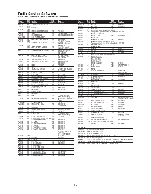
RVN4126 3.59100-386-9100-386/T DEVICERVN41772-CD2-3.5MCS/MTSRVN41821-CD2-3.5XTS3000/SABER PORTABLE YES RKN4046KHVN9085 3.51-20 R NO HLN9359 PROG. STAND RVN4057 3.532 X 8 CODEPLUG NO3080385B23 & 5880385B30 MDVN4965 3.59100-WS/T CONFIG KITRVN4053 3.5ASTRO DIGITAL INTERFACE NO3080385B23RVN41842-CD RKN4046A (Portable) 2-3.5ASTRO PORTABLE /MOBILE YES3080369B73 or0180300B10 (Mobile) RVN41831-CD3080369B732-3.5ASTRO SPECTRA MOBILE YES(Low / Mid Power)0180300B10 (High Power) RVN4185CD ASTRO SPECTRA PLUS MOBILE NO MANY OPTIONS; SEESERVICE BRIEF#SB-MO-0101RVN4186CD ASTRO SPECTRA PLUS MANY OPTIONS;MOBILE/PORTABLE COMB SEE SERVICE BRIEF#SB-MO-0101RVN4154 3.5ASTROTAC 3000 COMPAR.3080385B23RVN5003 3.5ASTROTAC COMPARATORS NO3080399E31 Adpt.5880385B34RVN4083 3.5BSC II NO FKN5836ARVN4171 3.5C200RVN4029 3.5CENTRACOM SERIES II NO VARIOUS-SEE MANUAL6881121E49RVN4112 3.5COMMAND PLUS NORVN4149 3.5COMTEGRA YES3082056X02HVN6053CD CT250, 450, 450LS YES AAPMKN4004RVN4079 3.5DESKTRAC CONVENTIONAL YES3080070N01RVN4093 3.5DESKTRAC TRUNKED YES3080070N01RVN4091 3.5DGT 9000 DESKSET YES0180358A22RVN4114 3.5GLOBAL POSITIONING SYS.NO RKN4021AHVN8177 3.5GM/GR300/GR500/GR400M10/M120/130YES3080070N01RVN4159 3.5GP60 SERIES YES PMLN4074AHVN9128 3.5GP300 & GP350RVN4152 3.5GP350 AVSRVN4150 3.5GTX YES HKN9857 (Portable)3080070N01(Mobile) HVN9025CD HT CDM/MTX/EX SERIES YES AARKN4083/AARKN4081RiblessAARKN4075RIBLESS NON-USA RKN4074RVN4098H 3.5HT1000/JT1000-VISAR YES3080371E46(VISAR CONV)RVN4151 3.5HT1000 AVSRVN4098 3.5HT1000/ VISAR CONV’L.YES RKN4035B (HT1000) HVN9084 3.5i750YES HLN-9102ARVN4156 3.5LCS/LTS 2000YES HKN9857(Portable)3080070N01(Mobile) RVN4087 3.5LORAN C LOC. RECV’R.NO RKN4021ARVN4135 3.5M100/M200,M110,M400,R100 includesHVN9173,9177,9646,9774YES3080070N01RVN4023 3.5MARATRAC YES3080070N01RVN4019 3.5MAXTRAC CONVENTIONAL YES3080070N01RVN4139 3.5MAXTRAC LS YES3080070N01RVN4043 3.5MAXTRAC TRK DUPLEX YES3080070N01RVN4178CD MC SERIES, MC2000/2500DDN6124AW/DB25 CONNECTORDDN6367AW/DB9 CONNECTOR RVN41751-CD Rib to MIC connector 1-3.5MCS2000 RKN4062BRVN41131-3.5MCS2000RVN4011 3.5MCX1000YES3000056M01RVN4063 3.5MCX1000 MARINE YES3000056M01RVN4117 3.5MDC/RDLAP DEVICESRVN4105 3.5MOBILE PROG. TOOLRVN4119 3.5MOBITEX DEVICESRVN4128 3.5MPT1327-1200 SERIES YES SEE MANUALRVN4025 3.5MSF5000/PURC/ANALOG YES0180355A30RVN4077 3.5MSF5000/10000FLD YES0180355A30RVN4017K 3.5MT 1000YES RTK4205CRVN4148 3.5MTR 2000YES3082056X02RVN4140 3.5MTRI 2000NORVN41761-CD MTS2000, MT2000*, MTX8000, MTX90001-3.5*programmed by DOS which is included in the RVN4176RVN4131 3.5MTVA CODE PLUG FIXRVN4142 3.5MTVA DOCTOR YES3080070N01RVN4131 3.5MTVA3.EXERVN4013 3.5MTX800 & MTX800S YES RTK4205CRVN4097 1-CD MTX8000/MTX9000,MTS2000,MT2000*,* programmed by DOS which is included in the RVN4176HVN9067CD MTX850/MTX8250MTX950,MTX925RVN4138 3.5MTX-LS YES RKN4035DRVN4035 3.5MX 1000YES RTK4203CRVN4073 3.5MX 800YES RKN4006BHVN9395 P100, P200 LB, P50+, P210, P500, PR3000RVN4134 3.5P100 (HVN9175)P200 LB (HVN9794)P50+ (HVN9395)P210 (HVN9763)P500 (HVN9941)PR3000 (HVN9586)YES RTK4205HVN9852 3.5P110YES HKN9755A/REX1143 HVN9262 3.5P200 UHF/VHF YES RTK4205RVN4129 3.5PDT220YVN4051 3.5PORTABLE REPEATER Portable rptr.P1820/P1821AXRVN4061C 3.5PP 1000/500NO3080385B23 & 5880385B30 RVN5002 3.5QUANTAR/QUANTRO NO3O80369E31RVN4135 3.5R100 (HVN9177)M100/M200/M110/M400YES0180358A52RVN4146 3.5RPM500/660RVN4002 3.5SABER YES RTK4203CRVN4131 3.5SETTLET.EXEHVN9007 3.5SM50 & SM120YESRVN4039 3.5SMART STATUS YES FKN5825AHVN9054 3.5SOFTWARE R03.2 P1225YES3080070N01HVN9001 3.5SOFTWARE R05.00.00 1225LS YES HLN9359AHVN9012 3.5SP50RVN4001N 3.5SPECTRA YES3080369B73 (STANDARD)0180300B10 (HIGH POWER) RVN4099 3.5SPECTRA RAILROAD YES3080369B73RVN4110 3.5STATION ACCESS MODULE NO3080369E31RVN4089A 3.5STX TRANSIT YES0180357A54RVN4051 3.5SYSTEMS SABER YES RTK4203BRVN4075 3.5T5600/T5620 SERIES NO3080385B23HVN9060CD TC3000, TS3000, TR3000RVN4123 3.5VISAR PRIVACY PLUS YES3080371E46FVN4333 3.5VRM 100 TOOLBOX FKN4486A CABLE &ADAPTORRVN4133 3.5VRM 500/600/650/850NORVN4181CD XTS 2500/5000 PORTABLES RKN4105A/RKN4106A RVN41002- 3.5XTS3000 ASTRO PORTABLE/MOBILERVN4170 3.5XTS3500YES RKN4035DRIB SET UPRLN4008E RADIO INTERFACE BOX (RIB)0180357A57RIB AC POWER PACK 120V0180358A56RIB AC POWER PACK 220V3080369B71IBM TO RIB CABLE (25 PIN) (USE WITH XT & PS2)3080369B72IBM TO RIB CABLE (9 PIN)RLN443825 PIN (F) TO 9 PIN (M) ADAPTOR (USE W/3080369B72 FOR AT APPLICATION) 5880385B308 PIN MODULAR TO 25 PIN ”D” ADAPTOR (FOR T5600 ONLY)0180359A29DUPLEX ADAPTOR (MOSTAR/TRAXAR TRNK’D ONLY)Item Disk Radio RIB Cable Number Size Product Required Number Item Disk Radio RIB Cable Number Size Product Required NumberUtilizing your personal computer, Radio Service Software (RSS)/Customer Programming Software (CPS)/CustomerConfiguration Software (CCS) enables you to add or reprogram features/parameters as your requirements change. RSS/CPS/CCS is compatible with IBM XT, AT, PS/2 models 30, 50, 60 and 80.Requires 640K RAM. DOS 3.1 or later. Consult the RSS users guide for the computer configuration and DOS requirements. (ForHT1000, MT/MTS2000, MTX838/8000/9000, Visar and some newer products —IBM model 386, 4 MEG RAM and DOS 5.0 or higher are recommended.) A Radio Interface Box (RIB) may be required as well as the appropriate cables. The RIB and cables must be ordered separately.Licensing:A license is required before a software (RVN) order is placed. The software license is site specific (customer number and ultimate destination tag). All sites/locations must purchase their own software.Be sure to place subsequent orders using the original customer number and ship-to-tag or other licensed sites; ordering software without a licensed customer number and ultimate tag may result in unnecessary delays. To obtain a no charge license agreement kit, order RPX4719. To place an order in the U.S. call 1-800-422-4210. Outside the U.S., FAX 847-576-3023.Subscription Program:The purchase of Radio ServiceSoftware/Customer Programming/Customer ConfigurationSoftware (RVN & HVN kits) entitles the buyer/subscriber to three years of free upgrades. At the end of these three years, the sub-scriber must purchase the same Radio Service Software kit to receive an additional three years of free upgrades. If the sub-scriber does not elect to purchase the same Radio Service Software kit, no upgrades will be sent. Annually a subscription status report is mailed to inform subscribers of the RSS/CPS/CCS items on our database and their expiration dates.Notes:1)A subscription service is offered on “RVN”-Radio Service Software/Customer Programming/Customer Configuration Software kits only.2)“RVN” software must only be procured through Radio Products and Services Division (RPSD). Software not procured through the RPSD will not be recorded on the subscription database; upgrades will not be mailed.3)Upgrades are mailed to the original buyer (customer number & ultimate tag).4)SP software is available through the radio product groups.The Motorola General Radio Service Software Agreement is now available on Motorola Online. If you need assistance please feel free to submit a “Contact Us” or call 800-422-4210.SMART RIB SET UPRLN1015D SMART RIB0180302E27 AC POWER PACK 120V 2580373E86 AC POWER PACK 220V3080390B49SMARTRIB CABLE (9 PIN (F) TO 9 PIN (M) (USE WITH AT)3080390B48SMARTRIB CABLE (25 PIN (F) TO 9 PIN (M) (USE WITH XT)RLN4488ASMART RIB BATTERY PACKWIRELESS DATA GROUP PRODUTS SOFTWARERVN4126 3.59100-386/9100T DEVICES MDVN4965 3.59100-WS/T CONFIG’TN RVN41173.5MDC/RDLAP DEVICESPAGING PRODUCTS MANUALS6881011B54 3.5ADVISOR6881029B90 3.5ADVISOR ELITE 6881023B20 3.5ADVISOR GOLD 6881020B35 3.5ADVISOR PRO FLX 6881032B30 3.5BR8506881032B30 3.5LS3506881032B30 3.5LS5506881032B30 3.5LS7506881033B10 3.5LS9506881035B20 3.5MINITOR III8262947A15 3.5PAGEWRITER 20008262947A15 3.5PAGEWRITER 2000X 6881028B10 3.5TALKABOUT T3406881029B35 3.5TIMEPORT P7308262947A15 3.5TIMEPORT P930NLN3548BUNIVERSAL INTERFACE KITItem Disk Radio NumberSize Product。
正格子与倒格子的关系

R • K N l1l2l3
h1h2h3
N 0,1,2,
晶面ABC在三个坐标轴上的截距分别是 a1 h1, a2 h2 , a3 h3
则矢量
AC
OA
OC
a1
h1
a3
/
h3
AB
OA
OB
a1
h1 a2 / h2
Kh1h2h3
h1b1
h2b2
h3b3
K h1h2h3
•
AC
(h1b1
h2b2
h3b3 ) •
(a1
h1 a3 / h3 )Leabharlann b1•a1
b3
•a3
0
K h1h2h3
•
AB
(h1b1
h2b2
h3b3 ) • (a1
h1 a2 / h2 )
b1 • a1 b2 • a2 0
所以
K
与晶面
h1h2h3
(h1
,
h2
,
h3
)
正交
3.倒格矢
K h1h2 h3
的长度与晶面(h1, h2, h3)的面间距成反比
在上一页的图中,最靠近原点的晶面ABC在 a1轴上的截
有
(a3
a1
)
(a1
a2
)
[(a3
a1
)
•
a2
]a1
[(a3
a1
)
•
a1]a2
a1
则有
1 3
(a2
a3
)
•
a1
1 2
(a2
a3
)
•
a1
1
即正格子与倒格子的体积互为倒数
UbiQ-231 4.3”情境控制电脑 用户手册说明书

用户手册UbiQ-2314.3”情境控制電腦UbiQ-231用户手册ii版權聲明隨附本產品發行的檔為研華公司2012年版權所有,並保留相關權利。
針對本手冊中相關產品的說明,研華公司保留隨時變更的權利,恕不另行通知。
未經研華公司書面許可,本手冊所有內容不得通過任何途徑以任何形式複製、翻印、翻譯或者傳輸。
本手冊以提供正確、可靠的資訊為出發點。
但是研華公司對於本手冊的使用結果,或者因使用本手冊而導致其它協力廠商的權益受損,概不負責。
認可聲明ARM 是ARM 公司的註冊商標。
TI OMAP 是TI 公司的註冊商標。
Windows 是微軟公司的註冊商標。
所有其他產品名稱或商標均為其各自所有者的財產。
UbiQ-231用戶手冊中文第一版,參照UbiQ-231用戶手冊英文第一版。
符合性声明CE本產品已經通過CE 環境規格檢測。
測試條件之一是在工業環境中進行產品操作。
為了使產品免受ESD (靜電放電)和EMI 洩露造成的損害,強烈建議用戶使用符合CE 標準的工業產品。
FCC B 级根據FCC 規則第15款,本設備已經過檢測並被判定符合B 級數位設備標準。
這些限制旨在為商業環境下的系統操作提供合理保護,使其免受有害干擾。
本設備會產生、使用和發射無線電頻率能量。
如果沒有按照手冊說明正確安裝和使用,可能對無線電通訊造成有害干擾。
但即使按照手冊說明進行安裝和使用,也並不能保證不會產生干擾。
若本設備會對無線電或電視信號接收產生有害干擾,用戶可通過開、關設備進行確認。
當本設備產生有害干擾時,用戶可採取下面的措施來解決干擾問題:⏹調整接收天線的方向或位置⏹增大本設備與接收器之間的距離⏹將本設備的電源接頭插在與接收器使用不同電路的電源插座⏹若需技術支援,請諮詢經銷商或經驗豐富的無線電/ 電視技術人員料号:XXXXXXXXXX 第一版中国印刷2012年3月警告!若未經相關權威機構明確批准而擅自更改或修理設備,則使用者操作本設備的權利可能會被取消。
2130-2240D-2250DN-联想2240L维修手册

4.1 纸张送入故障........................................................................................................................ 2-21 4.1.1 纸盒的撮纸功能失效...................................................................................................... 2-21 4.1.2 无纸张送入 .................................................................................................................... 2-21 4.1.3 手动进纸槽中无纸张...................................................................................................... 2-22 4.1.4 双页送入........................................................................................................................ 2-22 4.1.5 卡纸............................................................................................................................... 2-22 4.1.6 纸面上的污点 ................................................................................................................ 2-24 4.1.7 纸张歪斜送入 ................................................................................................................ 2-24 4.1.8 纸张皱褶........................................................................................................................ 2-24 4.1.9 纸张卷曲........................................................................................................................ 2-25 4.1.10 双面打印时只能打印单面 ............................................................................................ 2-25
Omega HH-25KF HH-25KC HH-25TF HH-25TC 温度计说明书

HH-25KF HH-25KC
$125 125
0.1°F 1°F
0.1°C 1°C
-40 to 199.9°F -120 to 1999°F
-40 to 199.9°C -120 to 1999°C
±(0.5% rdg + 1.0°F) ±(1.0% rdg + 2.0°F)
±(0.5% rdg + 0.5°C) ±(1.0% rdg + 1.0°C)
3UHVVXUH 6WUDLQ DQG )RUFH
Displacement Transducers, Dynamic Measurement Force Sensors, Instrumentation for Pressure and Strain Measurements, Load Cells, Pressure Gauges, Pressure Reference Section, Pressure Switches, Pressure Transducers, Proximity Transducers, Regulators, Pressure Transmitters, Strain Gauges, Torque Transducers, Valves
L-31
)UHHSKRQH _ ,QWHUQDWLRQDO _ )D[ _ 6DOHV#RPHJDFRXN
ZZZRPHJDFRXN
81,7(' 67$7(6 ZZZRPHJDFRP 7&20(*$
OCW-3, OMEGACARESM extends standard 2-year warranty to a total of 5 years ($31), $125 + 31 = $156.
- 1、下载文档前请自行甄别文档内容的完整性,平台不提供额外的编辑、内容补充、找答案等附加服务。
- 2、"仅部分预览"的文档,不可在线预览部分如存在完整性等问题,可反馈申请退款(可完整预览的文档不适用该条件!)。
- 3、如文档侵犯您的权益,请联系客服反馈,我们会尽快为您处理(人工客服工作时间:9:00-18:30)。
图7 从上至下依次为第0、1、2、3级的波形
3.脉冲整形电路
由输入输出波形图可见整形后为方波,且频率相等。
如图8所示。
图8 从上到下依次为被测信号波形、整形后波形通过示踪器观察可知,脉冲整形电路的输入输出波形的周期、频率相同。
4.计数器和显示电路测试
当输入50kHz的时,显示为50kHz.如图9所示。
图9 显示电路
5.电路整体性能测试
被测信号输入1kHZ的正弦波,档位选择10倍档CBA=001,图中波形从上至下依次为被测波形、10倍档位波形、多谐振荡器产生的波形。
波形和最后的显示结果如图12所示。
图10 从上到下依次为1kHz的被测波形、10倍档位波形、多谐振荡器产生的波形
通过四踪示波器得到电路中的数据,被测波形的周期为1ms,多谐振荡器产生的波形的周期是1ms,10倍档位波形的周期如图12所示为10.000ms。
五、结论
这个周期测量电路可以测量方波、正弦波、三角波等波。
基准时钟信号周期为lms。
有4个测量档位,分别1kHz、100Hz、10Hz、1Hz档。
测量范围是lkHz 到200kHz。
测量的最小精度是lkHz。
结果用LED数码管显示,有手动开始和复位功能。
六、性价比
综合各种因素来看,该方案设计的电路经济实惠,操作简单。
该电路中的元器件数量较少,价格低廉,电路的总体性能比较稳定,误差较小,测量范围大。
由此可见该方案的性价比还是很高的,很具有实际应用性。
七、课设体会及合理化建议
通过本次课程设计,我的数字电子技术基础的理论知识有了进一步巩固,对所学的各芯片的功能和使用方法有了更加清晰的认识。
亲自动手实验也使我更加熟练地运用各种器材设备来解决一些实际问题。
在此过程中,我也进一步熟悉了所用的Multisim仿真软件和实验箱的功能和使用方法。
为以后进一步学习相关知识打下了很好的基础。
但我也发现了在学习中没有发现和注意到的缺点和不足,比如对芯片的相关命令和使用方法还不够熟练,在使用过程中,电路连接得也不是很高效和完美;仿真时,对软件和硬件的使用还不熟练,还有很多功能没有使用过和不会使用,甚至不知道。
通过这次课程设计,我发现了许多不足,我会在以后的学习中尽量弥补我的这些不足,努力学习相关知识,尽量多使用Multisim仿真软件和各种设备来解决生活中的一些实际问题,来提高自己。
我还会虚心的向同学和老师请教,向学习好的同学学习,使自己尽快的赶上他们,甚至超过他们,争取学以致用,在以
后的工作中
参考文献
1.童诗白、华成英主编者. 模拟电子技术基础. [M]北京:高等教育出版社,2008年
2.谭博学主编. 集成电路原理与应用. [M]北京:电子工业出版社,2006年
3.谢自美主编. 电子线路设计、实验、测试.[M]武昌:华中科技大学出版社,1992年
4.戴伏生主编.基础电子电路设计与实践.[M]北京:国防工业出版社,2007年
5.张庆双主编.全新实用电路集粹上、下册.[M]北京:机械工业出版社,2008年
附录I 总电路图
附录II 元器件清单
序号编号名称型号数量
1 U9 555定时器LM555CM 1
十进制同步计数器74LS160D 7
2 U1、 U2、U3、U4、
U6、U7、U15
3 U10、U11、U12 LED数码显示管DCD_HEX 3
4 U
5 八选一数据选择器74LS151D 1
5 U30、U31 与非门NAND2 2
6 U17A 与门74S08D 1
7 U13、U16 或门7405N 2
8 J3、J4、J5 开关Key=A 3
9 J1 手动开关Key=space 1
10 C1 电容C1=10nF 1
11 C2 电容C2=1.0uF 1
12 R1、R2 电阻R1=R2=48.089 KΩ 2。