ud75_Multiband Operation
16位高性能并行输出A_D转换器ADS7805及其应用

16 位高性能并行输出 A / D 转换器AD S7805 及其应用黄晓芩 刘延冰 华中理工大学 ( 430074)摘要 A D S 7805 是一种高性能 16 位 A / D 转 机 、微机系统 , 而不需另加电源 。
( 6) 采用 28 脚 013 英寸双列直插封装 , 比 标准的 28 脚双列直插封装体积缩小一倍 。
换芯片 , 它自带采样/ 保持器 , 最高采样频率可 达 100k Hz ,采样结果全 16 位并行输出 ,采用单+ 5V 电源供电 。
文中还详细介绍了 A D S 7805的 功 能 及 使 用 方 法 , 并 给 出 了 A D S7805 与 80C196 单片机的接口电路和编程方法 。
关键词 A / D 转换器 并行接口 单片机概 述随着计算机应用的普及 , A / D 转换成为微 机控制中一个不可缺少的重要环节 。
在某些应 用场合 , 使用者对采样精度的要求很高 , 12 位A / D 转换器已不能满足要求 。
16 位 A / D 转换器应用得最多的是串行输出 A / D 转换器 , 但 串行输出 A / D 转换器与并行总线接口麻烦 , 读数慢 , 在一些对采样频率要求很高的场合不 适用 。
相比之下 ,并行输出的 A / D 芯片则更有 优势 。
美国 BB 公司出品的 16 位 A / D 芯片 A D S 7805 可适用于这样的应用场合 , 它具有如 下突出特点 。
( 1) 自带采样/ 保持器 , 方便对交流信号的 采样 。
( 2) 连续两次采样之间只需间隔 10μs , 最高采样频率可达 100k Hz 。
( 3) 转换结果全 16 位并行输出 , 具有三态缓冲功能 ,与 16 位数据总线接口方便 。
同时 ,可由 B Y T E 信号线动态控制输出数据高低八位 的位置 (如图 1) , 这样与 8 位数据总线接口时 , 可分两次读出 16 位数据 ,极大方便了使用者 。
集成DA转换器及其应用.ppt

3 DAC0832引脚排列
8位 D/A 转换器
RFB
UREF IOUT2
IOUT1
RFB AGND VCC DGND
IOUT1:模拟电流输出端1
当输入数据全1时,输出最大
IOUT1
255U REF 256 RFB
当输入数据全0时,IOUT1=0
IOUT2:模拟电流输出端2
IOUT1+IOUT2=常数
单极性输出时,IOUT2接模拟地。
3 DAC0832应用—正弦波发生器
采用直通控制方式:
四个控制端接低电平 ILE接高电平
4 DAC0832应用—正弦波发生器
仿真电路图
4 DAC0832应用—正弦波发生器
参考程序
仿真结果
5 课后思考
DAC0832有模拟地(AGND)和数字地(DGND), 为了减少干扰, 在PCB布线时需要如何处理?
D0~D9:数据输入端 IOUT1:电流输出端1 IOUT2:电流输出端2 Rf:10KΩ反馈电阻引出端 Vcc:电源输入端 UREF:基准电压输入端,可正可负 GND:地
2 AD7520应用--锯齿波发生器
再10来位一二个进计制数加脉法冲计,数则器计从数全器0加的到值全由1全,0电变路成的全1, 输模出拟电输压出也电从压最uo由大0值V跳增变加成到0最。大值。 如果计数脉冲不断,则可在电路的输出端得到周期性
3 DAC0832引脚排列
D7~D0
8位 输入
寄存器
ILE
1 &
LE1 10
8位 DAC 寄存器
LE2
CS 0
&
WR1 0
XFER
&
WR2
一种低功耗12位30MHz流水线A_D转换器

一种低功耗12位30M H z流水线A/D转换器钱文荣1,戴庆元1,朱红卫2(1.上海交通大学微纳科学技术研究院,上海 200030;2.上海华宏N EC电子有限公司,上海 201203)摘 要: 设计了一种12位30M Hz1.8V流水线结构A/D转换器,该A/D转换器采用相邻级运算放大器共享技术和逐级电容缩减技术,其优点是可以大大减小芯片的功耗和面积。
电路采用级联一个高性能前置采样保持单元和五个运放共享的1.5位/级MDAC,并采用栅压自举开关和动态比较器来降低功耗。
结果显示,该ADC能够工作在欠采样情况下,有效输入带宽达到50M Hz。
在输入频率达到奈奎斯特频率范围内,整个ADC的有效位数始终高于10.4位。
电路使用TSMC0.18μm1P6M CMOS工艺,在30M Hz全速采样频率下,电路功耗仅为68mW。
关键词: A/D转换器;运放共享;栅压自举开关;动态比较器中图分类号: TN79+2 文献标识码: A 文章编号:100423365(2008)022******* Design of a Low Pow er122Bit30M H z Pipelined A/D ConverterQ IAN Wenrong1,DA I Qingyuan1,ZHU Hongwei2(1.Research I nstit ute of Micro/N ano S cience and Technolog y,S hanghai J i aotong Universit y,S hanghai200030,P.R.China;2.S hanghai H uahong N EC Elect ronics Com pany,L t d.S hanghai201203,P.R.China)Abstract: A122bit30M Hz1.8V CMOS pipelined analog2to2digital converter(ADC)was presented,in which a power efficient op2amp sharing architecture between two successive stages was adopted to reduce chip area and pow2 er dissipation.The capacitor scaling approach was used for the same purpose.The ADC was cascaded with a high performance sample/hold unit and five op2amp sharing stages.Simulation result showed that the ADC could operate at under2sampling rate,with an effective input bandwidth up to50M Hz.The ADC exhibited an effective number of bits(ENOB)above10.4for input f requencies up to Nyquist rate at30M Hz.Implemented in TSMC’s0.18μm 1P6M CMOS process,the circuit had a power dissipation of only68mW at30M Hz sampling frequency.K ey w ords: A/D converter;Op2amp sharing;Bootstrapping switch;Dynamic comparatorEEACC: 1265H1 引 言近年来,高速高精度A/D转换器在各种应用中的需求越来越大。
MSTP20171001000002-华为光网络MSTP考试-每日3题

MSTP20171001000002 华为光网络MSTP考试每日3题1、<★★>【单选题】关于设备调测前检查,以下那一项描述是错误的()。
A、设备调测前,必须检查设备已经安装接地,且接地良好。
B、AUX单板有多个RJ-45接口,它们接入的信号是一样的,倘若误插,对设备和单板没有影响。
C、AUX单板上LAMP1和LAMP2是机柜告警灯输出端口和机柜告警灯输入级联端口,调测时如果误插,将会引起短路。
D、设备调测前,需要保证NMS网管系统正确安装//参考资料:《OptiX OSN 7500产品文档V200R013C20_03 调测之确认设备调测条件》//答案解析:AUX单板有多个RJ-45接口,但它们的信号定义不同,请注意不要误插,以免引起内部芯片损坏。
//参考答案:(B)2、<★★>【单选题】采用NMS网管(U2000)对OptiX OSN 3500进行单站调测创建网元时,默认网元用户名为()。
A、adminB、rootC、szhwD、lct//参考资料:《OptiX OSN 3500产品文档V200R015C20_03 调测之创建单个网元》//答案解析:缺省网元用户为:root;缺省密码为:Changeme_123。
//参考答案:(B)3、<★★>【单选题】PQ1单板需要使用接口单板,以下单板中哪种单板是阻抗类型为75Ω的接口单板。
()A、D75SB、D12SC、D12BD、D34S//参考资料:《OptiX OSN 7500产品文档V200R013C20_03 硬件描述之PDH单板》//答案解析:D75S单板用于输入输出32路E1电信号,需配合PQ1单板使用。
单板的电接口指标:E1码型为HDB3码,阻抗75(Ω)。
D12S单板用于输入输出32路E1/T1电信号,需配合PQ1或PQM单板使用。
单板的电接口指标:E1码型为HDB3码,阻抗120(Ω)。
T1码型为B8ZS码、AMI码, ,阻抗100(Ω)。
PowerFlex755变频器 操作说明
目录一、POWERFLEX 750 变频器面板简介 (3)1、人机接口模块(HIM)简介 (3)1.1、View 软键 (4)1.2、REF 软键 (4)1.3、EDIT 软键 (4)1.4、P AR# 软键 (4)1.5、状态屏幕下的语言切换软键 (4)1.6、启动和停止按键 (4)1.7、功能键 (4)1.8、文件夹按键 (5)2、复位到出场设置 (5)3、调整面板亮度 (7)4、设置时间 (8)5、备份参数/删除备份参数 (9)5.1、使用CopyCat功能 (9)5.2、创建CopyCat文档 (10)5.3、删除CopyCat文档 (11)6、带电拔插操作面板 (12)7、快速访问参数 (13)8、使用启动向导 (13)设置电机控制模式 (15)输入电机铭牌数据 (16)设置速度反馈装置 (18)设定速度限制 (20)方向测试、自整定和惯量测试 (20)组态速度参考和斜坡速率 (24)组态输入和输出 (25)二、POWERFLEX 750 变频器接线 (27)1、P OWER F LEX753典型接线图 (27)2、P OWER F LEX753主板内置I/O位置 (28)3、P OWER F LEX755典型接线图 (29)4、P OWER F LEX755主板内置I/O位置 (30)5、PF750系列变频器扩展I/O模拟量跳线 (31)6、PF750系列变频器端口的说明 (31)三、POWERFLEX 750 变频器参数 (32)1、PF750变频器常用参数简单说明 (32)1.1、PF750变频器常用参数(00号端口) (32)1.2、安全速度卡相关参数(Safe Speed Monitor) (34)1.3、双通道编码器反馈卡相关参数(Dual Encoder) (35)1.4、24VDC扩展I/O卡相关参数(I/O Module 24V) (35)1.5、13号端口PF755内置以太网参数 (35)1.6、14号端口PF750内置DeviceLogix (35)1.7、数字量输入组态举例 (35)1.8、数字量输出组态举例 (35)1.9、使用模拟量输入作为速度源组态举例 (36)四、POWERFLEX 750 变频器故障处理 (37)五、其他 (38)1、变频器相关参考资料 (38)附件一:POWERFLEX755变频器和POWERFLEX700变频器比较 (39)1.P OWER F LEX755和P OWER F LEX700电气性能比较 (39)2.P OWER F LEX755和P OWER F LEX700功能比较 (40)3.P OWER F LEX755和P OWER F LEX700外形尺寸比较 (40)4.P OWER F LEX755和P OWER F LEX700接线图的比较 (41)5.P OWER F LEX755和P OWER F LEX700参数的比较 (43)一、PowerFlex 750 变频器面板简介1、人机接口模块(HIM)简介下图显示了20-HIM-A6面板的按键。
西门子技术问题总汇

文档标题
如何设置模拟量输入模板 SM 431-7KF00的温度补偿? 如何解决 SIMATIC BATCH 的 IL43基本设备上 hotfix 安装的问题? 如果通过 PCS7 V6.1 SP1 DVD 单独安装 SIMATIC BATCH Report 需要注意哪些设置? 为什么冗余模拟量输出模块的每个通道只有一半电流输出? 使用WinCC/Web Navigator V6.1 SP1需要什么样的操作系统和软件? 是否 COM PROFIBUS 可以使用所有版本的 GSD 文件? 如何在 WinCC flexible 中组态与S7 控制器的 Profinet 连接? 如何在操作面板上设定定时器时间, 同时如何输出定时器的剩余时间? 数据块初始值与实际值的含义 如何通过窗口对象滚动条步进调节过程值参数? 使用 SINAUT ST7 向电子邮箱接受方发送文本信息 SMS 需要做何设置? 可以使用CPU317-2PN/DP替代在iMap中组态的CPU315-2PN/DP吗? 什么情况下插入C-PLUG卡或者C-PLUG有什么作用? 通过一台PC,可以使用哪种方式访问与IWLAN/PB link PNIO或IE/PB link PNIO连接的PROFIBUS设备? 当在SINAUT网络中使用4线变压器应该注意哪些设置? 在 SINAUT 网络中,使用MD3拨号调制解调器作为专线调制解调器时,要进行哪些设置? 如何安装 DCF77 天线, 当选择 DCF77 天线时需要注意什么? 使用SINAUT ST7向传真机发送文本信息时,需要进行哪些设置? 在 SINAUT 项目中发送短消息必须进行哪些特殊服务的设置? 如何在S7-300 PN CPU和CP343-1之间建立一个open TCP 通讯连接,以及如何进行数据交换? 如何在两个S7-300 PN CPU之间建立一个open TCP 通讯连接,以及如何进行数据交换? 哪些控制系统可以成功与SINAUT ST7一起使用? 使用“零-Modem”电缆连接 TIM 模块应该注意什么? 当用 SINAUT 诊断工具的ST1协议进行诊断时,为什么TIM的状态不能显示? TIM 3V-IE 和 TIM 3V-IE Advanced 模块在以太网上通信时使用哪个端口号? 如何对没有接入网络的S7-200CPU编程? 掉电后,LOGO!的程序会丢失吗? 从 PCS7 V6.1 起,为什么没有分配任何 hierarchy (PH) 的 测量点(变量)通过编译不能在OS中自动创建相应的变量? 在SFC中,如何实现从一个 Sequencer 跳出后回到另一个 Sequencer 的某个固定位置并继续执行? 如何实现过程变量的平均值归档? 存储文件的目标路径和备份可选路径有何作用? WinCC变量归档中如何实现采集周期小于500ms的变量归档? 为什么在 OS 上会显示如下信息“时间跳变通知-永久切换为从站模式”? 在西门子A&D产品支持网站是否可以下载关于ET200M的手册? 在S7-400上怎样安装冗余电源? UDT改变后怎样更新使用UDT产生的数据块。 为什么在FB块中使用OUT变量赋值被调用FB块的IN变量时出现错误信息34:4469? 如何查看4-mation导入-导出错误 不能正确引导8212-1QU IBM/Lenovo M52 ThinkCentre 实时趋势更新缓慢的原因 如何保存变量名字典CSV文件的格式
传输设备误码问题处理经验
传输设备误码问题处理经验误码问题是传输设备日常维护过程中经常碰到的问题。
现在把误码问题处理的一些经验与大家分享。
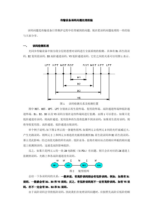
一、误码检测机理光同步传输设备中按分段分层的思想对误码进行全面系统的检测。
具体有B1再生段误码、B2复用段误码、B3高阶通道误码、V5低阶通道误码。
它们之间的关系可以用图1表示。
图1 误码检测关系及检测位置图中RST、MST、HPT、LPT分别表示再生段终端、复用段终端、高阶通道终端和低阶通道终端。
B1、B2、B3以及V5误码分别在这些终端间进行监测。
由图1可以看出,如果只是低阶通道有误码,则高阶通道、复用段和再生段将监测不到该误码;如果再生段有误码,则将导致复用段、高阶通道、低阶通道出现误码。
举个例子说明:如下图2所示的一条链性组网,如果网元2收网元3间的光纤衰减过大,产生光路误码,则网元2上和网元3相连的光板将检测到B1再生段误码和B2再生段误码,那么受此影响,经过该段光路的所有高阶、低阶业务,也将在相应站点的相应单板的相应通道上检测到误码,这就是高阶影响低阶。
反之,如果只是网元1的一块2M电路板(如PD1)有问题,则只会在对应的2M通道上监测到误码,光路上和各高阶通道没有误码。
图2 链型组网总结一下各误码间的关系:一般来说,有高阶误码则会有低阶误码。
例如,如果有B1误码,一般就会有B2、B3和V5误码;反之,有低阶误码则不一定有高阶误码。
如有V5误码,在不一定会有B3、B2和B1误码。
由于高阶误码会导致低阶误码,因此我们在处理误码问题时,应按照先高阶后低阶的顺序来进行处理。
二、引起误码的常见原因一般来说,以下一些情况会引起误码:(1)线路收光功率异常(过高或过低),会引起再生段误码及其它低阶误码(2)交叉板或时钟板故障,经常会引起多块线路板都有高阶通道出现误码(3)线路板故障,有可能引起再生段或复用段误码(4)支路板故障,有可能引起低阶通道误码(5)设备温度过高,也会造成各种误码的出现总结一下,可把引起误码的原因分为两大类:1. 外部原因1)光纤性能劣化、损耗过高。
隐形故障简析
隐性故障简析8月15日目录1.CTRX测量说明 (3)2.TCH分配失败问题 (4)3.MRR测量报告 (8)4.注意事项 (14)1.CTRX测量说明一.创CTRX测量以下命令对整个BSC下所有TRX创自适应SCANCTRX:Create SCANCTRX:NAME=bss:5/SCANCTRX:50, OBJLST=SELFADAPTING(0), START=1-JAN-1995,STOP=31-DEC-2099,RECINT=ALL(0),RXLVR=7-15-23-31-39-47-55,TIMADVR=1-2-3-4-5-6-7,FER=10-20-30-40-50-100-200,FERSERTYPE=TCH_EFS;以上黄色部分最好不要改动,取缺省值便于后面处理。
三.原始统计文件示例四.原始统计文件说明以上个原始文件表格为例,第1行第3格数值为177,说明上行的测量中,电平级别为0(表示上行电平在-110dbm和-102dbm之间)质量级别为0的采样点个数为177个,其它类推。
五.对原始文件的处理说明原始文原始文件的统计中电平共分8个等级,从RXLEV_0到RXLEV_7电平依次升高,每个等级代表一个跨度为8db的电平范围RXLVR=7-15-23-31-39-47-55,这8个等级电平上门限分别为-103dbm,-95dbm,-87dbm,-79dbm,-71dbm,-63dbm,-55dbm,>-48dbm,我们对这些进行平均化处理,每个电平段取其中间点的电平值,如所有RXLEV_0的采样点就认为其电平为-106dbm(考虑到基站灵敏度-110dbm左右),然后按照如下公式计算得出载频上电平平均值:RxlevAvr=((-106)*RXLEV_0采样点数+(-98)*RXLEV_1采样点数+…+(-50)*RXLEV_7采样点数)/(RXLEV_0采样点数+RXLEV_1采样点数+…+ RXLEV_7采样点数) 质量的处理也与上面的方法相同,不过更简单,因为质量是独立的8个值而不是8个范围。
- 1、下载文档前请自行甄别文档内容的完整性,平台不提供额外的编辑、内容补充、找答案等附加服务。
- 2、"仅部分预览"的文档,不可在线预览部分如存在完整性等问题,可反馈申请退款(可完整预览的文档不适用该条件!)。
- 3、如文档侵犯您的权益,请联系客服反馈,我们会尽快为您处理(人工客服工作时间:9:00-18:30)。
OPEN INFORMATION USER DESCRIPTION 1(12)KI/ERA/SVN/NRA LARS KLOCKAR8508775842000-10-24D 75/1553-HSC 10312Uen ERA/SVN/NRAC (Lennart Blixt)Uppgjord —Prepared Datum —Date Rev Dokumentnr —Document no Godkänd —Approved Kontr —Checked Tillhör/referens —File/reference EUser Description,Multiband Operation Copyright ©Ericsson Radio Systems AB 2000.All rights reserved.No part of this document may be reproduced in any form without the written permission of the copyright holder.Disclaimer Trademarks Contents Page 1Introduction 22Glossary 22.1Concepts 22.2Abbreviations and Acronyms 23Capabilities 24Technical description 34.1General 34.2Power and frequency capability of an MS 34.3Broadcast of measurement frequencies 44.4Measurement reporting 44.5GPRS 44.6Related Counters 44.7Main changes in Ericsson GSM system R8/BSS R8.055Engineering guidelines 55.1General 55.2Traffic control by sufficient SS threshold,active mode 55.3Traffic control by sufficient SS threshold,idle mode 65.4GPRS 75.5Load dependent traffic distribution 85.6Neighbour relations 85.7Subscriber differentiation 95.8Classmark 3Messages 96Parameters 96.1Main controlling parameters 96.2Parameters for special adjustments 106.3Value ranges and default values 117References 12SEIF v2.3,1IntroductionAn operator with licenses to operate both in the GSM900and1800frequencyband can choose to have the GSM900network and the GSM1800networkcombined into the same network.Each cell in a multiband network has frequencies from only one frequencyband.The Multiband operation feature allows cell re-selection,assignmentand handover between the GSM900cells and the GSM1800cells.With the Multiband Operation feature it is also possible to have GSM900and/or GSM1800cells together with GSM1900cells,supported by the sameBSC.However,it is not possible to perform cell re-selection,assignment orhandover between GSM1900and the other bands.2Glossary2.1ConceptsE-GSM Extended GSM900band including the Primary GSM900bandand the G1.G1Extension band defined for GSM900at880-890MHz(uplink)and925-935MHz(downlink).P-GSM Primary GSM900band defined at890-915MHz(uplink)and935-960MHz(downlink).2.2Abbreviations and AcronymsCLS Cell Load SharingGPRS General Packet Radio ServiceHCS Hierarchical Cell StructurePBCCH Packet Broadcast Control ChannelSS Signal Strength3CapabilitiesA combined GSM900and GSM1800network provides a very efficientsolution for building a cost efficient high capacity network together withgood coverage.The radio waves on the900MHz and1800MHz frequency band have differentpathloss characteristics.GSM900cells generally have a larger range thanGSM1800cells.If cells from the different frequency bands can be joined intoone single network,GSM900cells can be used to cover large areas withlimited traffic density.GSM1800cells can provide additional capacity in highdensity areas.Operators with an existing GSM900network can use theadditional1800MHz band to increase the capacity of their network.Operatorswith an existing GSM1800network may not have full coverage and they canuse GSM900to increase both coverage and capacity.In a multiband network,the system supports cell re-selection,assignmentand handover between GSM900cells and GSM1800cells for multibandMSs.Multiband MSs,and single band MSs(GSM900or GSM1800)canco-exist.This has two benefits:1An operator that is changing the network from a single band(GSM900or GSM1800)to a multiband network is still able toserve the single band MSs on both frequency bands.2A multiband subscriber will be able to use the multiband MS in apure GSM900network as well as in a pure GSM1800network.GSM1900cells must always form a separate network.With GSM900andGSM1800the operator can choose whether to have separate networksor one combined network.4Technical description4.1GeneralA Mobile services Switching Centre(MSC)is able to handle BSCs of differentsystem types,which means that it is possible to have GSM900BSCs,GSM1800BSCs and GSM1900BSCs connected to the same MSC.Correspondingly,a BSC is able to handle cells of different system types,whichmeans that it is possible to have GSM900cells,GSM1800cells and GSM1900cells connected to the same BSC.Each cell must however only containfrequencies related to one system type.A multiband MS is able to receive,transmit and measure on GSM900frequencies as well as on GSM1800frequencies.A multiband MS performsneighbouring cell measurements on GSM900cells as well as on GSM1800cells.Both types of cells are evaluated in the idle mode cell re-selectionalgorithm and in locating.This means that cell re-selection,assignment andhandover can be performed between the frequency bands.A single band MS will not measure neighbouring SS on frequencies it can nothandle.This means that a single band MS will never be allocated a channel inthe wrong frequency band.4.2Power and frequency capability of an MSClassmark3(CM3)contains MS capabilities such as multiband and powercapability of each band,extended-GSM band and multislot.MSs inform thenetwork of their capability during the call set up procedure and at locationupdating.Regarding multiband it is important for the network,besides to knowthe multiband capability itself,to know the MS power capability in the otherfrequency band,not currently used.With parameter ECSC=YES there is a bitin system information3telling the MS to send Classmark Change,containingCM3(and CM2)as soon as possible after access.CM2contains the MSpower capability related to the frequency band on which the MS is residing.The MSC needs to have the CM3information in case of an inter BSChandover.The MSC then transfers the CM3information to the target BSC.If a multiband MS performs an inter-BSC handover,and the MSC does nothave the CM3information,the target BSC will not have the correct informationregarding the power capabilities of the MS.If the handover was between twocells belonging to the same frequency band,the target BSC will treat the MSas a single band MS for the remainder of the call.If the inter BSC handoverwas between two frequency bands,depending on the content of CM2theresult will either be a handover failure,or the target BSC will use incorrectvalues regarding the MS power capability.In order to reduce the load on the A interface(between the BSC and theMSC),the sending of CM3is possible to suppress or delay by parameterCLMRKMSG.For CLMRKMSG=0,the BSC will always transfer the messageto the MSC.For CLMRKMSG=1the message is suppressed in all situations,i.e.the CM3information is never transferred to the MSC.CLMRKMSG=3means that the sending is suppressed at location updating but not at callset-up.Finally it can be delayed even further,until an inter-BSC handover isperformed(CLMRKMSG=2).4.3Broadcast of measurement frequenciesAn MS performs neighbouring cell measurements in idle mode as well as inactive mode.The information about which neighbours that shall be measuredon is broadcasted to all MSs in the cell.A single band MS ignores frequenciesit can not handle.The frequencies of neighbouring cells are given by parameter MBCCHNO,see User Description,Double BA lists.With this parameter GSM900frequencies as well as GSM1800frequencies can be defined as neighbouringfrequencies in a multiband network.4.4Measurement reportingA multiband MS measures the SS from GSM900neighbours as well as fromGSM1800neighbours.It is possible to control how many GSM900cells andGSM1800cells respectively that are reported in the measurement report byparameter MBCR.This implies that not always the six strongest cells will bereported.MBCR determines how many of the decoded neighbours of the otherband that shall be reported,at the expense of neighbours in the current band.If the report is still not full,more neighbours from the other band are included.4.5GPRSThere is no restriction for dualband GPRS.4.6Related CountersIn order to give the operator statistic measurements to adjust parametersfor controlling the traffic between frequency bands to off-load the GSM900cells to a maximum,the object type CELLDUALT is introduced to supportthe following counters:TFDUAL-TRALACC Traffic level accumulator.It gives continuous information on the number of seized channels for dualband MSs.TFDUAL-NDROPNumber of abnormally terminated dualband connections.TFDUAL-CASSALLNumber of assignment complete for all MS power classes.TFDUALAS-SALLNumber of assignment attempts for all MS power classes.The counters are defined per cell and are stepped only for dualband MSs.See User Description,Radio Network Statistics for details.4.7Main changes in Ericsson GSM system R8/BSS R8.0Changes in the Engineering guidelines due to enhanced HCS with8layersand8bands(see User Description,Hierarchical Cell Structures).New counters for dualband MSs(see4.6).5Engineering guidelines5.1GeneralA combined900and1800network depends on the same functionality andplanning principles as a single band network.However,in order to utilise thegiven spectrum efficiently,it is often desired to direct the traffic in accordancewith the distribution of multiband MSs,single band900MSs and1800MSs.Therefore multiband operation makes its own use of other features.Thisengineering guideline is based on the typical scenario of a GSM1800layer implemented on top of a mature GSM900system in order to provideadditional capacity.In that case it is important to give priority to1800cell ina efficient but safe way.Also,more attention must be paid to the numerousneighbour relations.5.2Traffic control by sufficient SS threshold,active modeIn the early stages of a multiband network the presumed high number of1800frequencies and low penetration of multiband phones means large sparecapacity in the1800cells and also low interference.Therefore these cellsshould be favoured whenever they have sufficient SS.This can be done withHCS,Locating and idle mode cell re-selection.The easiest method in active mode is HCS(see User Description,HierarchicalCell Structures).When the900cells and1800cells co-exist the900MHzSS will in general be higher than the1800MHz SS.The natural choice ofcarrier would be the stronger900MHz but with HCS it is possible to direct thetraffic to the higher priority1800MHz frequency band if the SS in that cellis above an absolute SS threshold.Two HCS options are available,one with8layers and8HCS bands andthe other with3layers and no HCS band.The full HCS feature offers thecell two thresholds instead of one.The layer threshold LAYERTHR is usedto limit interference between layers within the same frequency band.Theband threshold HCSBANDTHR is used to prioritise between non interferinglayers.GSM900cells can be specified in one band and GSM1800cell withinanother band.Since each band can consist of layer structures there is onepriority mechanism dealing with multiband and another mechanism usedbetween layers(for example microcells and macrocells)within each band.Since the GSM1800cells are not interfered by the GSM900cells,an1800cell can very well be the serving cell in an area with considerably higher SSfrom the GSM900cells.If the frequency planning within the GSM1800layer is not too aggressive,noise rather than interference limit the GSM1800coverage allowing a low SS threshold.HCSBANDTHR=95is a reasonablelevel for the1800band.Of course a low threshold like-95dBm requires shortSS and quality filters,(E.g.3to5s).The SS may fall quickly and serving cellmust not disappear within the time it takes to complete a handover.More than5s must be allowed due to filtering,time to identify new neighbours andto allow TINIT(see User Description,Locating)to elapse after a possibleprevious handover.A threshold of-95dBm allows time enough to performhandover out in normal urban areas.There are however situations with fastmoving mobiles where the threshold must be higher.In these situations theSS falls a lot more than10dB in the5s before a handover can be performed.The MS will be trapped in the1800cell and drop the connection.This problemhas been seen for example during rapid shifts of height and direction athighway exits.Those kinds of areas must be identified and a threshold of-85dBm or higher should be used in affected cells.The HCS priority is considered already in the assignment stage(see UserDescription,Assignment to Other Cell).If a call set-up is performed in900although1800has sufficient SS,the assignment can be done directly inthe best1800cell provided that CM3is received by the BSC early in theassignment stage.5.3Traffic control by sufficient SS threshold,idle modeTo keep the number of handovers down,a higher priority to1800cellsis desired in idle mode.In cell reselection the C2algorithm(see UserDescription,Idle Mode Behaviour)provides the possibility to apply a CellReselection Offset,parameter CRO,to a high priority cell at cell re-selection.By that the cell becomes favoured a given number of dB in the cell reselection.At low SS it is however dangerous to allow high offsets instead of lettingthe strongest cell be selected.Therefore the use of CRO requires that thefavoured cell cannot be accessed at too low SSs.Parameter ACCMINbecomes important;above which a multiband MS has to camp on1800,evenif the signal is too weak,and below which the MS is not allowed to camp onthe1800band at all.The MS should continuously listen to its paging groupand abandon a cell where paging messages tend to be lost.This leaky bucketbehaviour with common parameter settings,see User Description,Idle ModeBehaviour,gives however no guarantee that the MS selects a strong enoughcell,if possible.From experience it is found that an offset forces the MS tocamp on an1800cell although the cell is too weak to deliver the pagingsproperly.The MS remains silent although there are stronger900cells wherethe pagings would succeed.Call set-up seems to be a smaller problem sincethe MS either change cell after failure or succeeds with call set-up followed by immediate handover or assignment handover out.Below follows three strategies for how to set ACCMIN,associated to three types of situations:1High difference in SS between bands,some1800singleband MSsHigh CRO is necessary which means that ACCMIN1800mustbe high enough to allow e.g.paging.If ACCMIN1800is set tothe lowest safe value instead of the lowest possible value,the 1800coverage area is not decreased noticeable.A safe valuemay differ between networks and MSs but ACCMIN1800=103is a suggestion.Strategy1gives a small discrepancy in theidle and active mode cell borders(unlike strategy3)but this isregarded less important than possible single band1800MSs inthe system,or possible extra coverage added by the1800cells. 2Small difference in SS between bandsIf the SSs of1800and900are almost equal,a small offset of2to4dB can be effective.A few dB offset is excused withoutadjustment of ACCMIN in1800.A small favour to1800iscompensated by less interference and perhaps better uplinkdue to Tower Mounted Amplifier(TMA).3No single band1800MSs,minimum of inter-band handovers It is also assumed that CRO is high.If there are no singleband1800MSs in the system,and if the1800cells provideno additional coverage compared to the GSM900system,ACCMIN1800could be set according to the sufficient SSthreshold in active mode i.e.HCSBANDTHR1800if HCS isused for1800macrocells.Especially when900to1800handovers mean inter-BSC or even inter-MSC handovers,itis advantageous to have about the same cell borders in idleand active mode.5.4GPRSThe GPRS MSs perform an autonomous cell selection in both packet idlemode and packet transfer mode(see User Description,GPRS Cell Selection).For an MS in GPRS mode currently listening to a cell with a PBCCH C31andC32criteria are used to perform the cell re-selection and GPRS mobilesprioritise the bands,but not the layers,in the same order as HCS(see UserDescription,Hierarchical Cell Structures).This solves the task of prioritising inidle mode.In case no PBCCH is configured in the cell C1and C2criteria are used justlike for all circuit switched MSs in Idle Mode.In this case GPRS mobiles willnot see the HCS structure.5.5Load dependent traffic distributionThe traffic load in cells fluctuates over time and some cells may be congested.Also the increasing number of multiband phones may require re-tuning of theHCS thresholds.Ericsson's GSM system has load dependant features fortraffic distribution in order to temporary move traffic from highly loaded cellsto less loaded.In case of congestion,assignment to worse cell(see User Description,Assignment to Other Cell)to the other band would save otherwise lostconnections.It is recommended to allow assignment to worse cell from both1800and900cells.Assignment to worse cell is a method to considerablyincrease the trunking efficiency in the network.AWOFFSET should be highfor the inter-band cell relations due to the non existing interference betweenbands.Since assignment to the other band is only possible for multiband MSs withboth1800and900coverage,not all new call set-ups can be saved by theassignment to worse cell possibility.CLS offers a possibility to off-load a highlyloaded cell before congestion(see User Description,Cell Load Sharing).The creation of spare channels enable single band MSs or multiband MSswithout coverage of the other band to grab resources in highly loaded cells.CLS only moves candidates close to the cell border but in a co-siting situationthis could mean a large fraction of MSs.CLS operates in areas where SSor path loss ranking is used.In combination with HCS that means betweencells belonging to the same band and same layer where both are above orbelow their thresholds.5.6Neighbour relationsIn the case a single band network is expanded to multiband,the existingneighbour lists are probably too long to allow a simple addition of a new layerof cells.In a multiband network there is no room for unnecessary neighbourrelations.Therefore the introduction of multiband often requires a throughoutsurvey of neighbour lists.A missing900neighbour could mean dropped calland a missing1800neighbour could mean less capacity.When1800cells are given high priority,it is important that a handover can beperformed quickly when the SS is below the threshold.With too few defined900neighbours to the1800cell,the MS may be trapped and therefore dropthe connection since HCS allows the cell border to reach deep into a nonco-sited900cell.Therefore the1800to1800relations must be optimised inorder to allow enough1800to900relations.The900to1800relations on the other hand are mainly for capacity and not ascritical.It is enough to add the co-sited1800cells and perhaps a few moreif a need is discovered.Neighbouring Cell List Optimization Expert(seeUser Description,Neighbouring Cell List Optimization Expert(NOX))givesinformation about new neighbour relations that would be suitable to addand information about neighbour relations that are not used and thereforecan be removed.It is recommended to use MBCR=2.It is then possible for an MS to performa handover,or an assignment,to a weak GSM1800cell.5.7Subscriber differentiationAt the same time as traffic is directed to the1800band with its spare capacity,some of these low interfered high quality1800MHz channels can be reservedfor certain privileged subscriber groups.With the use of Differential ChannelAllocation(see User Description,Differential Channel Allocation)a fraction ofthe channels in a cell can be defined as inaccessible for the non privilegedsubscribers.There is a possibility to reserve all channels in a cell for certainsubscribers.Subscribers that are not allowed to access will get the sameresponse as at congestion.Therefore DCA requires assignment to worse cell.Example:It was desired that low paying subscribers in a multiband networkshould only use1800cells while the rest could use both bands.The solutionwith all900TCHs defined inaccessible for some subscribers was satisfactorybut had some drawbacks:1The SDCCH load in900(no CRO)was high since assignmentto worse cell can mean several seconds set-up delay.2The displayed service in idle mode(900)does not alwayscorrespond to actual active mode coverage(1800).3The configuration with900and1800in different BSCs is notpossible but this is not recommended anyway.DCA checks arenot done at inter-BSC handover.5.8Classmark3MessagesIt is important to set parameter ECSC to YES because the multiband versionof Ericsson's GSM system relies on early classmark sending.Without CM3the multiband capability of an MS will be unknown and a missing CM3in targetBSC at handover means that the power class of the MS will be misunderstood.How and when CM3is further delivered to the MSC is controlled by parameterCLMRKMSG.The extra BSC/MSC signalling at call set-up due to CM3ismarginal.Therefore it is recommended to always send CM3to the MSCdirectly(CLMRKMSG=0),at least when the fraction of MSs sendingClassmark Change is small.The other choices may be preferred if MSCsignalling is a bottleneck.To forward CM3at access but not at locationupdating(CLMRKMSG=3)could be a safe way to reduce the load,but moretesting must be done until general recommendations can be given.If nomultislot MSs are expected and E-GSM band is not used,it could be optimalto wait until inter-BSC handover(CLMRKMSG=2)before CM3is forwarded. 6Parameters6.1Main controlling parametersGSYSTYPE is the global system type for the whole BSC.It defines which typeof cells the BSC contains.GSYSTYPE can have four values:•GSM900:All cells in the BSC is of type GSM900•GSM1800:All cells in the BSC is of type GSM1800.•GSM1900:All the cells in the BSC is of type GSM1900•Mixed:The BSC contains cells of more than one typeOnly cells that are supported by GSYSTYPE should be connected.GSYSTYPE must therefore be set to mixed before cells of another bandare connected to the BSC.CSYSTYPE is the cell system type.It can have three values:•GSM900:The cell system type is GSM900•GSM1800:The cell system type is GSM1800.•GSM1900:The cell system type is GSM1900MODE defines whether the BSC is in single or in multi band mode.Theparameter shall be set to MULTI in order to support cell re-selection,assignment and handover between GSM900cells and GSM1800cells.When the parameter is set to SINGLE,each frequency band forms a separatenetwork.MBCCHNO is the list of the neighbouring cells frequencies(see UserDescription,Double BA lists).The parameter is set per cell.ECSC indicates if early classmark sending should be used by the MS.In orderto allow multiband operation the value must be YES.Extended GSM andmultislot also require the value YES.The parameter is set per cell.6.2Parameters for special adjustmentsMBCR defines the number of neighbours from each frequency band that shallbe reported in the measurement report.The parameter can take the valuesbetween0and3,where the different settings mean:0:The multiband mobile station reports the strongest(up to six)identified neighbours irrespective of thefrequency band used in the cells.1:The multiband mobile station attempts to report the strongestidentified neighbour in each frequency band,excluding thefrequency band of serving cell.The remaining positions in thereport are used for neighbours from the serving band.If positionsstill exist,more neighbours of the other bands are included.2:The multiband mobile station attempts to report the2strongestidentified neighbours in each frequency band,excluding thefrequency band of serving cell.The remaining positions in thereport are used for neighbours from the serving band.If positionsstill exist,more neighbours of the other bands are included.3:The multiband mobile station attempts to report the3strongestidentified neighbours in each frequency band,excluding thefrequency band of serving cell.The remaining positions in thereport are used for neighbours from the serving band.If positionsstill exist,more neighbours of the other bands are included.The parameter is set per cell.CLMRKMSG suppresses or delays the sending of frequency and powercapability of a multiband MS from the BSC to the MSC.The parameter cantake the values between0and3,where the different settings mean:0:the sending is neither suppressed nor delayed1:the sending is suppressed in all situations2:the sending is delayed until an inter-BSC handover3:CM3sent at call set-up is not supressed but CM3sent atlocation updating is suppressed except when an inter-BSChandover during location updating is performedThe parameter is a BSC exchange property,and is set per BSC.6.3Value ranges and default valuesTable1Controlling parametersParameter name DefaultvalueRecommendedvalueValue range UnitGSYSTYPE-GSM900,GSM1800,GSM1900,MIXED CSYSTYPE-GSM900,GSM1800,GSM1900 MODE-SINGLE,MULTIARFCN MBCCHNO1to124(GSM900P-GSM)0,975to1023(GSM900G1)512to810(GSM1900)512to885(GSM1800)MBCR020to3ECSC NO YES NO,YES000to3CLM-RKMSG7References1User Description,Double BA lists2User Description,Hierarchical Cell Structures3User Description,Locating4User Description,Assignment to Other Cell5User Description,Idle Mode Behaviour6User Description,Cell Load Sharing7User Description,Neighbouring Cell List Optimization Expert(NOX)8User Description,Differential Channel Allocation9User Description,Radio Network Statistics10User Description,GPRS Cell Selection。