LCE-A规格书下载(报警灯)
埃里电子温控器系列 0-10 Vdc 控制器型号手册说明书

14
Features: • Adjustable heat anticipator • Fahrenheit and Celsius capability • Mercury free
ON/OFF THERMOSTATS The 31-100 series thermostats are designed for applications which require a single pole/double throw switch, adjustable heat anticipator and fixed cooling and anticipator.
Thermostats, Non-Digital
Erie offers advanced design in electronic microprocessor based thermostats and controllers. Erie combines the simplicity of a thermostat with the versatility and power of a controller. Ease of installation is combined with the flexibility of applications and maximum compatibility. Proportional plus integral (PI) control algorithms with advanced adaptive logic guides the microprocessor based units. This provides precise and stable control under varying system capacity and load conditions, without the need for tuning or calibrating the control algorithm.
阿尔法冷 Eisstation 80 DC-LT 高亮说明书

What is it?Alphacool Eisstation 80 DC-LTHighlightsThe Eisstation 80 DC-LT is part of the Alphacool Enterprise Solutions series. The combination of pump top and reservoir has been designed to fit into compact servers and workstations. Depending on the in-stallation method, the Eisstation 80 DC-LT even fits into 2U server housings.- part of the Enterprise Solutions Series - extreme small form factor - reservoir integrated - pump is fully enclosedArticle textThe Eisstation 80 DC-LT is part of the Alphacool Enterprise Solutions series. The combination of pump top and reservoir has been designed to fit into compact servers and workstations. Depending on the in-stallation method, the Eisstation 80 DC-LT even fits into 2U server housings.What is the special feature?Thanks to the compact dimensions and the variable mounting options, the Eisstation 80 DC-LT is suitable for very compact water-cooled systems. The optionally available DC-LT pump is also available in different performance levels and can easily operate smaller water loops. The entire DC-LT Eisstation is made of acetal and is extremely resistant and durable.What are the mounting options?The 80 DC-LT Eisstation is supplied with an adhesive Velcro mat and special feet. The Velcro mat allows the lowest installation position and is also the easiest to use. A part of the Velcro mat is simply stuck to the desired installation location and the other side to the floor of the Eisstation 80 DC-LT. This means the positioning is completely down to you. The enclosed feet were designed for different mounting possi-bilities. The installation height can be varied. In addition, installation at an angle of 30 or 90° is also possi-ble. In addition, decoupling feet are included with the accessories to reduce the noise of the already quiet pump further.Installation of the pump and filling!The fill port has a diameter of 25 mm and has been designed to be particularly large so that filling can be done easily by hand. This means that the water loop can also be filled without a filling aid such as a spray bottle or funnel. To mount the pump a base plate must be removed, this is only held in place by two screws. Then the O-ring supplied with the DC-LT pump is inserted and the pump is put on and fastened with the two screws. The cable of the pump then just needs to be led through the cable opening.IN and Out?The Eisstation 80 DC-LT consists of a pump top and a reservoir. If both components are used, the IN is located on the side of the reservoir. The OUT is also located on the side of the pump top. You can vary the locations a little by dismantling both parts from each other and simply reassembling the reservoir by turning it 90 or 180°. If the reservoir is not used, the pump top has an additional IN on the opposite side of the OUT.Small, compact and versatile, this is the Eissstation 80 DC-LT from the Alphacool Enterprise Solution se-ries.。
艾迪克斯 35 型号 RV 型 CO 丙烷气体报警器 用户手册说明书

RECREATIONAL VEHICLE (RV) Combination Carbon Monoxide and Gas AlarmUSER’S MANUALModel 35-741, 35-742PATENT US 7,248,156 ALL RIGHTS RESERVED 35RV052008-4 ATTENTION:This user’s manual contains important Carbon Monoxide (CO) and gas alarm installation, operation, troubleshooting and warranty information. Read, follow, and keep this manual for future reference.NOTE: If you install or purchase this alarm for another person, give this manual to that person.DUAL SENSOR TECHNOLOGYThe SAFE-T-ALERT™ 35 Series combination CO / Gas Alarm is an alarm that combines into a single compact system, a powerful alarm that detects both Carbon Monoxide (CO) and explosive Propane (LPG)gas. The 35 Series uses the latest microprocessor technology combined with two electronic self-cleaning sensors that operate independently of each other. The combined unit can detect both CO and explosive gases simultaneously.This detector is UL Listed as a CO and Propane gas detector for RV use. Other explosive gases detected, but not tested by UL, include Acetone, Alcohol, Butane, and Gasoline all of which you may have in your RV.To prevent false alarms from brief “puffs” of gas the detector has a recheck cycle before alarming. If high levels of gas remain during the recheck cycle, the detector will alarm.The electronic CO sensor in your SAFE-T-ALERT TM CO alarm is very sensitive to CO gas. It will not react to safe levels of most other gases.WHY EVERY RV NEEDS A 35 SERIES CO AND GAS ALARM Everyone is at risk for carbon monoxide poisoning! Particularly sensitive are children, pregnant women, the elderly and people with lung or heart disease or anemia! Carbon monoxide (CO) is an odorless, colorless gas that prevents the blood from carrying oxygen to vital organs.CO is 200 times more likely to replace oxygen in the blood. The Consumer Product Safety Commission (CPSC) recommends using at least one CO alarm located outside of sleeping areas. For the best security, locate a CO alarm in each sleeping area. Safe-T-Alert CO alarms are available for secondary installations. Propane gas can cause explosions! Using propane requires taking safety precautions to avoid injury. LP gas is usually identified by an unpleasant odor. Certain conditions may make some people unable to detect this unpleasant odor. These conditions include advanced age, colds, allergies, and the use of tobacco, alcohol or drugs that may diminish the sense of smell.ABOUT THIS ALARMBecause CO is a colorless, odorless, tasteless and highly poisonous gas; it can endanger lives even at low levels of concentration. The CO Alarm will alert you to potentially dangerous situations. The following symptoms may be related to CO POISONING. Discuss these symptoms with ALL household members and RV guests:NOTE: Reported cases of CO gas poisoning indicate that whilevictims are aware they are not well, they are disoriented. They are unableto save themselves by exiting the RV or calling for assistance. Small children and pets may be affected first.Your SAFE-T-ALERT TM35 Series alarm helps protect your householdmembers and guests from CO produced while using your RV.CO gas isproduced when any type of fuel is incompletely burned. Potential sourcesof CO in and around your RV can include gas or diesel engine exhaust,portable space heaters, gas stoves and ovens, furnaces, defective engineexhaust systems, portable grills, other nearby RVs, portable generators,generator exhaust, and other propane-powered appliances. All are sources of CO.The following are also sources of CO that may affect your RV:∙Extended operation of unvented fuel burning appliances can build up high CO levels.∙An idling vehicle in an open or closed garage.∙Temperature inversions can trap exhaust near the ground.∙CO build up can be caused by reverse/negative venting of fuel burning appliances including; 1) Clogged, loose or faulty stacks or chimneys of(clothes dryers, furnaces and water heaters, etc.), 2) wind directionand/or velocity, 3) simultaneous operation of multiple fuel burningappliances, and/or exhaust fans.!WARNING:LIMITATIONS OF CO and GAS ALARMSTHIS ALARM WILL NOT WORK WITHOUT POWER.Somereasons for no alarm power are; a blown or missing fuse, broken wire, a faulty wire connection or circuit breaker, a discharged battery, cut lead wires, or improper supply (+) or ground (-) connections.THIS ALARM WILL ONLY INDICATE THE PRESENCE OF GAS AT THE SENSOR. CO or explosive propane/ gas gases may be present in other areas.MTI recommends installing CO alarms in all sleeping areas.Do not block or cover the alarm with any object that can prevent a gas leak orcarbon monoxide from reaching the sensor.THIS ALARM IS INTENDED FOR USE IN RV's. It is intended for use in inside locations of a RV. It is not designed to measure compliance with commercial and industrial standards.THIS ALARM MAY NOT BE HEARD. The alarm’s loudness is designed to meet or exceed regulatory standards; however, the alarm maynot be heard if alarms are located in remote locations or behind closed doors. Persons who are hard-of-hearing, have consumed alcoholic beverages, taken prescription, non-prescription or illegal drugs, may not hear the alarm.THIS ALARM IS DESIGNED TO DETECT CARBON MONOXIDE AND PROPANE GAS. THE ALARM IS NOT DESIGNED TO DETECT SMOKE, OR FIRE.THIS ALARM MAY NOT ALARM AT LOW CO LEVELS - It is not designed to measure compliance with the Occupational Safety Health Administration (OSHA) commercial or industrial standards. Individuals with medical problems may consider using warning devices, which provide audible and visual signals for CO concentrations under 30 ppm.THIS ALARM IS NOT A REPLACEMENT FOR INSURANCE. Always be sure your RV is fully insured.Warning: Installation of the device should not be used as a substitute for proper installation, use, and maintenance of fuel-burning appliances, including appropriate ventilation and exhaust systems.HOW TO PROTECT YOUR FAMILY CAUTION- The SAFE-T-ALERT TM 35 series combination CO and Gas Alarm is designed to protect individuals from the acute effects of carbon monoxide exposure and gas leaks. It will not fully safeguard individuals with specific medical conditions. If in doubt, consult a medical practitioner.To protect your family, you should:∙INSTALL THE ALARM PROPERLY.Carefully read and follow ALL the instructions in this manual. Test your unit every week. Alarms that do not work will not alert you to hazardous levels of CO or explosive gas. See the section, Test Procedure, in this manual for further information.∙MAKE REGULAR VISUAL INSPECTIONS. Check all fuel burning equipment including gas water-heaters, kitchen gas stoves, space heaters, gas dryers and all pilot lights. Check the color of the pilot flame. The color should be blue.∙MAKE REGULAR VISUAL INSPECTIONS OF THE ENGINE AND GENERATOR EXHAUST SYSTEMS. Cracked exhaust systems can allow CO to enter the living area.∙PROFESSIONALLY MAINTAIN YOUR ENGINE AND GENERATOR.Although gas engines and generators produce CO, a poorly tuned engine and generator will produce greater amounts CO.∙If you smell unusual odors you may have a gas leak, immediately call a local propane gas supplier or fire department to check for possible leaks.WHERE TO INSTALL∙Install the 35 series in the kitchen area near sources of a potential gas leaks. Some potential sources are a furnace, refrigerator, stove or oven.If potential sources of a gas leak are in separate areas, MTI recommends installing a gas alarm in each area.∙The Consumer Product Safety Commission recommends installinga CO alarm outside the sleeping area. The 35 series combinationCO and gas alarm complies with that recommendation.∙INSTALL ALARM at least 4 inches but not more than 20 inches off the floor.WHERE NOT TO INSTALL 35 SERIES ALARMS∙DO NOT INSTALL behind furniture, drapes, in closets or areas that will block gas flow to the alarm.∙DO NOT INSTALL within 12 inches (30cm) of opening windows, exterior doors, heating or return vents, or other drafty areas.∙DO NOT INSTALL on an outside wall.∙DO NOT INSTALL on a wall switch controlled by a power line, ground fault circuit or to a circuit breaker.∙NOTE: Older RVs may have little or no insulation and therefore are draftier. Carefully consider mounting locations.The following diagrams provide additional alarm installation information:INSTALLATION INSTRUCTIONSModel 35-741, 35-742!WARNINGFAILURE TO FOLLOW THESE INSTRUCTIONS MAY RESULT IN A MALFUNCTION OR FAILURE OF THE ALARM AND MAY VOID THE WARRANTY.SHOCK HAZARD: Turn off power before installing.Power Supply 12 VDC.Recommended Wire Size 14 GA. TO 18 GA.Connect the alarm to a properly fused circuit, maximum over protection device rating 15 amps.SPECIAL WIRING NOTICE: When replacing CCI Controls LP Gas Leak Detectors they may have two power leads. Safe-T-Alert units have one power lead. Simply connect the Safe-T-Alert power lead (Red) to the coach/house power supply and cap or remove the second power lead. DO NOT CONNECT BOTH POWER LEADS TO THE Safe-T-Alert ALARM – this will result in a dead chassis battery.Do not install within 12" ofa window that can openDo not install within12" of a doorDo not installwithin 12" of ventsDo Not install behinddrapes or furnitureRecommended Alarm LocationRecommended Alarm LocationDO NOT INSTALLFigure 3Connect to wiring or circuit that CANNOT be turned off by a switch or ground fault protector. Only use UL or recognized permanent wire connectors. It is acceptable to connect the 35 Series CO / LP gas alarm to the main disconnect. The alarm will be off along with all other 12 volt equipment when the main disconnect is turned to the off position. The RV must not be occupied when the main disconnect is in the off position.INSTALLATION INSTRUCTIONSFollow these instructions carefully. Failure to follow these instructions can damage the unit and void the warranty.Select a wall location at least 4” but not more than 20” off the floor.1.Disconnect the power supply being connected to.2.Model 35-741 requires a 1/2” hole be drilled where mounting.Model 35-742 requires a 1” clearance to recess the case. Cut a5 3/8” W x 2” H hole3.C onnect the RED (+) power lead to the fused circuit. Connectthe BLACK lead to Ground (-).4.Fasten the unit to the wall using the two screw holes located onthe ends of the case5.Reconnect the power supply. Wait 10 minutes for warm up andthen test the alarm.NOTE: All connections must be in accordance with the National Electrical Code in the Unites Stated and the Canadian Electric Code in Canada .TEST PROCEDURE!WARNINGTO REDUCE THE RISK OF CARBON MONOXIDE POISONING OR PROPANE GAS EXPLOSION, TEST THIS ALARM’S OPERATION AFTER THE RV HAS BEEN IN STORAGE, BEFORE EACH TRIP AND AT LEAST ONCE PER WEEK DURING USE.!WARNINGWARNING: THE TEST BUTTON ONLY TESTS THE ALARM CIRCUIT NOT THE SENSORS. YOU MAY USE PROPANE OR BUTANE GAS TO TEST THE GAS SENSOR. Note it may take up to 10 seconds for the alarm to sound.TO TEST THE CO SENSOR USE A CAN OF SAFE-T-ALERT CO TEST GAS TO TEST THE 400 PPM CALABRATION POINT. DO NOT TRY TO GENERATE CO TO TEST THE ALARM. The TEST/RESET button tests all ELECTRICAL functions of the alarm. It does not check the sensor operation.The alarm may be tested at any time -The TEST/Mute switch is located on the front of the alarm Press and hold the test button for 1 second. The alarm is working properly if the GREEN indicator light changes color to RED and the horn beeps 4 times. The Gas LED should also blink Red. IMPORTANT - If this alarm does not test properly return it immediately for repair or replacement.OPERATIONEach time the unit is first powered up, the CO sensor requires a ten (10) minute initial warm-up period to clean the sensor element and achieve stabilization. The GREEN LED indicator will flash on and off during the 10 minute warm-up period. This unit cannot go into a CO alarm during the warm-up period. To test your unit during the warm-up period, press the test button. See Test Procedure in this manual. After the warm-up period, the GREEN power ON indicator should glow continuously If the ON indicator light does not light, see the section, Trouble-Shooting Guide, in this manual for further information. Do not attempt to fix it yourself. Gas Alarm: When you power the alarm, it has a warm-up period of approximately 1 minute. This unit cannot go into a gas alarm during the warm-up period. After 1 minute the alarm can detect explosive gas. Simultaneous CO and Gas Alarms— Because the risk of a propane gas explosion is generally a more serious danger, your alarm unit gives the gas alarm a higher priority during simultaneous alarm condition.If your unit generates alarms for both Gas and CO at the same time, the gas LED will flash red and the beeper will sound. The CO LED will be a solid Red until the CO is ventilated out of the RV, at which time the LED will return to the Green operational/safe color.Brownout Protection - The unit can tolerate short power interruptions and brownouts where the circuit voltage drops as low as 1VDC. If the brownout lasts too long, the unit will reset and operate as described above.LOW POWER OPERATIONThis alarm will operate normally down to7 VDC. Do not operate this alarm below 7 VDC.VISUAL AND AUDIBLE ALARM SIGNALSThis SAFE-T-ALERT TM CO / Propane Gas Alarm is designed to be easy-to-operate. The alarm has two indicator lights that display a specific color for each monitored condition. There also is a matching sound pattern for alarm conditions.CO ALARMThe Red CO LED will flash and the alarm will sound 4 “BEEPS” then silent for 5 Seconds. These signals indicate that the CO level is over 35 ppm. IMMEDIATE ACTION IS REQUIRED. See Procedures To Take During An Alarm. This cycle will continue until the TEST/Mute button on the front of alarm is pressed. Ventilate the RV. The RED light will stay ON until the CO has cleared, or the alarm will reactivate in approximately 6 minutes if the CO is still present. DO NOT RE-ENTER THE RV. This alarm will return to normal operation after the RV s properly ventilated.PROPANE GAS ALARMThe Red LED will Flash and the alarm will sound a steady tone whenever a dangerous level of propane gas is detected. IMMEDIATE ACTION IS REQUIRED. See Procedures Take During A Gas Alarm The detector will continue to alarm until the Test/Mute switch on the front of the alarm is pressed. Ventilate the RV. The RED Gas LED will continue to flash until the gas has cleared, or the gas alarm will reactivate in approximately 5 minutes if the gas is still present. DO NOT RE-ENTER THE RV. This alarm will return to normal operation after the RV s properly ventilated. MALFUNCTION/SERVICE SIGNAL If any malfunction is detected, the Gas LED will remain off and the Operational/CO LED will alternate Red/Green and the alarm will sound once every 15 seconds. Press the Test/Mute button. If the Test/Mute button does not clear the signals, check the battery voltage. I f the battery voltage is not low and the unit will not return to normal operation,immediately remove the alarm and return for service or warranty replacement.See the warranty section in this manual.TROUBLE-SHOOTING GUIDEUse this chart to trouble-shoot problems with this 35 series Alarm. PROBLEM CAUSE/SOLUTIONGreen Operational LED Off 1.Bad Wire Connection2. Reversed Wiring3. Main Power Off4. Missing or Blown FuseNo Sound When Testing Contact Customer ServiceNo Red LED When Testing Contact Customer Service Locked In Alarm Contact Customer Service MALFUNCTION ALARM LED 1. Check Battery VoltageRed/Green & BeepsEvery 15 SecondsBattery Voltage is Good and it 2. Contact Customer ServiceWill Not Reset To Normal operationEND OF LIFE ALARM3 days – Replace within 30 days. Customer Service 800-383-0269 HOW TO TAKE CARE OF YOUR ALARMThis CO / Propane Gas Alarm is designed to be as maintenance free as possible. To keep your alarm in good working order, you must:∙TEST THE ALARM WEEKLY. See the section, Test Procedure, in this manual for further information.∙VACUUM THE DUST OFF THE ALARM COVER. At least once a year (more frequently in dusty locations), use the soft brush attachment of your vacuum to clean the alarm cover.∙CLEAN THE ALARM COVER WHEN DIRTY. Wash the alarm cover by hand. Use a cloth dampened in clean water. Dry with a soft cloth.∙DO NOT SPRAY CLEANING AGENTS OR WAXES DIRECTLY ONTO THE FRONT PANEL. This action may damagePROCEDURES TO TAKE DURING AN CO ALARM Follow the alarm procedures for your country. The emergency number depends on your travel location.End of Life Signal – The Sensor has a 5 Year Service LifeAll 35 Series models include an End of Life (EOL) Signal indicating the sensor has reached the end of its service life and you must replace the alarm. The signal is the LED flashing RED RED GREEN GREEN with a beep every 25-30 seconds. The EOL Signal may be reset by pushing TEST / RESET button on the alarm. This will reset the EOL Signal for a period of 72 hours (3 days) for a total of up to 30 days. After 30 days the signal cannot be reset and the alarm must be replaced. DO NOT DISCONNECT THEALARM UNTIL YOU HAVE A REPLACEMENT ALARM AVAILABLE TO INSTALL.SPECIFICATIONSMODELS 35-741, 35-742POWER SUPPLY 12 VDCNOMINAL CURRENT DRAW 108 mAOPERATIONAL TEMPERATURE -40o F to +150o F -40o C to +66o CRELATIVE HUMIDITY 15% (+/- 5%) to 95% (+/- 4%)AUDIBLE OUTPUT 85 dB @ 10 feetGAS ALARM TRIGGER < 25% of the LEL of PropaneGAS LEVEL CONFIRMATION 8 Second Alarm DelayCO ALARM TRIGGER <15 Minutes @ 400 ppmCASE DIMENSIONS 35-741 6” W x 1.875”H x 1.375”D35-742 6.5”W x 2.75”H x 1.5”DWARRANTY 1 Year LimitedTESTING LABORATORY ETL IntertekSTANDARD UL 1484, Fourth EditionUL 2034, Third EditionCSA 6.19-01OWNERS REPLACEMENT RECORDReplace this SAFE-T-ALERT TM 35 SERIES CO / GAS propane alarm 5 years after date of installation. For new RV’s enter the month and year the RV was manufactured. If you are not sure, enter the month and year you purchased the RV or enter May and the model year of the RV (example May 2014), whichever is the earlier date. Installation Date: ____________________________ (Example: March 2014)Replace by Date _______________ ________________(5 years after Installation date – example: May 2019)If you don’t know the installation date, replace the alarm no later than 5 years after the production date on the back of the alarm.LIMITED PRODUCTS WARRANTYMTI INDUSTRIES, INC. warrants to the original retail purchaser that its products will be free from defects of material or workmanship for a period of One (1) year from the date of retail purchase. If proven to have been defective in original materials or workmanship and returned, delivery costs prepaid, MTI INDUSTRIES, INC. will replace this product free of charge.LIMITS OF WARRANTYReplacement is your exclusive remedy under this limited warranty or any other warranty (including any implied warranty of merchantability for a particular purpose). Any and all implied warranties or merchantability or fitness for a particular purpose shall be limited to the warranty period from the original date of retail purchase. MTI INDUSTRIES, INC., its dealers and distributors shall in no case be responsible or in any way liable for any incidental or consequential damages for any reason. Some states do not allow the limitation or exclusion of incidental or consequential damages, or allow limitations on how long an implied warranty lasts, so the above limitations may not apply to you. This warranty gives you specific rights, and you may also have other rights, which may vary, from state to state.PRODUCT NOT WARRANTEDNOTE-There are no user serviceable parts inside the case. Opening any SAFE-T-ALERT TM product for any reason voids the warranty.This warranty does not cover damage or failure resulting from acts of God, abuse, misuse, neglect, or faulty installation.WARRANTY RETURN PROCEDURESIt is MTI’s experience that a CO / Propane Gas Alarm is sounding f or a reason. Call, ask your dealer to call, or e-mail our Customer Service Department (as listed below) to trouble shoot the situation.Customer Service Phone No. - 800-383-0269Fax No. 847-546-9007*******************************Web Site: If Customer Service determines that the unit is defective, a Return Authorization (RA) number will be issued. No product will be accepted for service or replacement without first obtaining a RA number.If authorized, return this product to:MTI Industries, Inc.Warranty Dept. RA # (INSERT RA NUMBER HERE)31632 N. Ellis Drive Unit 301Volo, IL 60073NOTE: Mark the RA number in the area shown on the outside of the box!NOTE:35 Series is the basic unit with no interconnection and no relay. If you want these features order a custom 70-742 from MTI Industries.© MTI INDUSTRIES, Inc. 2013。
阿尔法冷Eiswolf 2 全覆盖GPU AIO冷却块说明书

The Alphacool Eiswolf 2 is the first full cover GPU AIO waterblock from Alphacool. It is based on the Alphacool GPX Eisblock Aurora GPX water block, a pump unit and a 360mm NexXxoS ST30 full copper radiator.The latter is equipped with the Alphacool Aurora Rise Digital RGB fans.•Full copper radiator •Virtually silent DC-LT 2 pump •Chrome-plated copper cooler •Digital aRGB illuminated cooler •Digital aRGB 120mm fans- ASRock Radeon RX 7900 XT Phantom Gaming OC, RX7900XT PG 20GO, 20GB GDDR6 (90-GA3XZZ-00UANF)- ASRock Radeon RX 7900 XT Taichi OC, RX7900XT TC 20GO, 20GB GDDR6- ASRock Radeon RX 7900 XTX Phantom Gaming OC, RX7900XTX PG 24GO, 24GB GDDR6- ASRock Radeon RX 7900 XTX Taichi OC, RX7900XTX TC 24GO, 24GB GDDR6V. 1.003 // 11.2023Alphacool Eiswolf 2 AIO - 360mm RX 7900XTX/XT Taichi -Phantom with BackplateAlphacool article number: 135151x Eiswolf 2 (pump, cooler, backplate) 1x Radiator NexXxoS ST30 360mm3x Fans Rise Aurora 120mm1x Montage Set GPU Cooler12x M3x6mm Screw 12x M3x30mm Screw1x PWM Cable Y-Adapter 1x aRGB Adapter1x Plug toolThe Alphacool Eiswolf 2 is the first full cover GPU AIO waterblock from Alphacool. It is based on the Alphacool GPX Eisblock Aurora GPX water block, a pump unit and a 360mm NexXxoS ST30 full copper radiator. The latter is equipped with the Alphacool Aurora Rise Digital RGB fans.Fullcover Waterblock?The Eiswolf 2 graphics card AIO water block not only cools the G PU with liquid but also all relevant components that require active cooling. This includes the graphics memory, the VRM and, if necessary, other components that require direct cooling. By using the Eisblock G PX Aurora water cooler, the cooling capacity is identical to that of a DIY graphics card water cooler.Chrome-plated copperThe cooler is made entirely of chrome-plated copper. A chrome plating is much harder than a nickel plating and therefore less sensitive to acids, scratches and damage. It completely eliminates the risk of chipping nickel plating. Additionally, chrome plating looks much more homogeneous and provides a shine that cannot be achieved by nickel plating. Chrome-plated coolers have previously only been used in the industrial sector in areas where extreme influences act on the coolers.PumpThe Eiswolf 2 has a pump unit in place of the normal connection terminal. This pump unit houses the DC-LT 2 pump. An improved and quieter version of the well-known DC-LT Low Noise Ceramic Pump. Despite looking rather large, the pump unit is only 5 mm wider than a normal connection terminal.Fittings and TubingAs with all new AIO units, Alphacool uses only TPV hoses from the Enterprise Solution range for (usually reserved for servers and workstations) in the Eiswolf 2. The tubing is made of EPDM/PP and are extremely heat-resistant, durable, and free of plasticizers. All fittings are also based on the Enterprise Solution range and match the TPV hoses perfectly.ExpandabilityBy using the quick-release fastener, the Eiswolf 2 can be connected to another Alphacool AIO unit to achieve a larger loop in seconds. Alphacool offers various prefilled components with which the loop can be easily extended. For safety reasons, the quick-release fasteners are firmly screwed together and not just plugged together.Lighting and fansThe Eiswolf 2 cooler has a digital RGB LED lighting, also called addressable RGB LEDs. They run along the entire back of the graphics card cooler and provide complete illumination of the water cooler. The pump unit is more discreet and offers a green glowing logo for Nvidia and a red glowing logo for AMD cards. The name "Eiswolf" on the pump unit remains unlit, discreetly in the background. The fan used is the Aurora Rise with 120mm. Due to the special blade design, the fan is extremely quiet and the addressable RG B LEDs provide brilliant illumination. The Alphacool Aurora Rise fan convinces with a max. static pressure of 3.17mm/H2O and offers a max. air flow of 119.8m3/h. The PWM control allows the fan to be controlled over a wide speed range. In addition, it offers a zero control. It can therefore be regulated down to 0 rpm and then starts with approx. 350 rpm.NexXxoS RadiatorAs with all AIO units, Alphacool uses radiators from the world renowned NexXxoS series. The full copper radiators offer a much higher cooling capacity than aluminium radiators and have contributed significantly to Alphacool's worldwide success.The combination of all of the components results in a solution that is as simple as an AIO solution to install, but with the performance of a pre-assembled and prefilled custom loop.Technical note!Due to long storage times and various transport routes, the liquid in the Eiswolf 2 AIO remains still for a long time. The ingredients of the liquid can therefore deposit and lead to a brownish discoloration. As soon as the pump starts operating, the ingredients mix again and the liquid should regain an approximately clear color. This is not a reason for complaint as neither the performance nor the function of the AIO are restricted by this. If the discolouration of the cooling liquid does not disappear after the AIO has been put into operation, please contact our support team via E-Mail (******************).Youwillreceivequickanduncomplicatedhelpthere.Drawing。
阿尔法冷(Alphacool)核心散热板系列EN表单说明书

Alphacool Core Distro PlateSeriesENTable of Contents DEInhaltsverzeichnisFRTable des matièresAccessories Zubehör Accessoires3 Pump installation: Insert O-Ring Pumpenmontage: O-Ring einsetzen Montage de la pompe: Insérer le O-Ring4 Pump installation Pumpenmontage Montage de la pompe4 Push Pin mounting Push Pin Montage Montage de Push Pin5 Push Pin mounting: With radiator Push Pin Montage: Mit Radiator Montage de Push Pin: Avec le radiateur6 Push Pin mounting: With Panel Push Pin Montage: Mit Panel Montage de Push Pin: Avec le panneau7 Configuration inlet and outlet Konfiguration Inlet und Outlet Configuration entrée et sortie8 Connect ARGB lighting ARGB Beleuchtung anschließen Connecter l'éclairage ARGB9 Connection pump cable Pumpenkabel anschließen Connexion du câble de pompe9 Filling and ventilation Füllen und Entlüften Remplissage et ventilation10 Dimensions in millimeter (mm)Abmessungen in Millimeter (mm)Dimensions en millimètre (mm)11Safety instructions Sicherheitshinweise Avis de sécuritéDigital guideDigitale Anleitung Guide digitalENAccessoriesDEZubehörFRAccessoires 1x 240 or 360Distro PlateA1xVPP-D5 Pump*B1x O-Ring*C1x Allen KeyD4x M4x22Pump Screw E1x Core Push Mount SetF1x Plug toolG1x ARGB Adapter HG1/4 Plug 5x for 3603x for 240I*Only the pre-assembled version includes the pump.*Nur bei der vormontierten Version ist die Pumpe im Lieferumfang enthalten.*Seule la version prémontée est livrée avec lapompe.ENPump installation: Insert O-Ring DEPumpenmontage: O-Ring einsetzenFRMontage de la pompe: Insérer le O-RingENPump installation DEPumpenmontageFRMontage de la pompeTighten the screws with 1.5Nm.Die Schrauben mit1,5Nm festziehen.Serrer les vis à 1,5Nm.4ENPush Pin mounting DEPush Pin MontageFRMontage de Push Pin5*Push Pin mounting: Use the screws (F) with the appropriate thread for your radiator.*Push Pin Montage:Verwenden Sie dieSchrauben (F) mit dempassenden Gewinde fürIhren Radiator.*Exemple de montage:Utilisez les vis (F) avecle filetage appropriépour votre radiateur.67ENConfiguration inlet and outlet DEKonfiguration Inlet und OutletFRConfiguration entrée et sortie* Please choose the port closest to your GPU configuration.* Bitte wählen Sie den Anschluss,der Ihrer GPU-Konfigurationam nächsten kommt.* Veuillez choisir le port le plus prochede la configuration de votre GPU.8ENConnect ARGB lighting DEARGB Beleuchtung anschließenFRConnecter l'éclairage ARGBENConnection pump cable DEPumpenkabel anschließenFRConnexion du câble de pompe9ENFilling and ventilation DEFüllen und EntlüftenFRRemplissage et ventilation10ENDimensions in millimeter (mm)DEAbmessungen in Millimeter (mm)FRDimensions en millimètre (mm)11Need help?Alphacool International GmbHMarienberger Str. 1D-38122 BraunschweigGermany Support: +49 (0) 531 28874-0Fax: +49 (0) 531 28874 - 22E-Mail:******************https:// We care!。
阿尔法冷 Eisbaer 200 CPU 黑色水暖器说明书
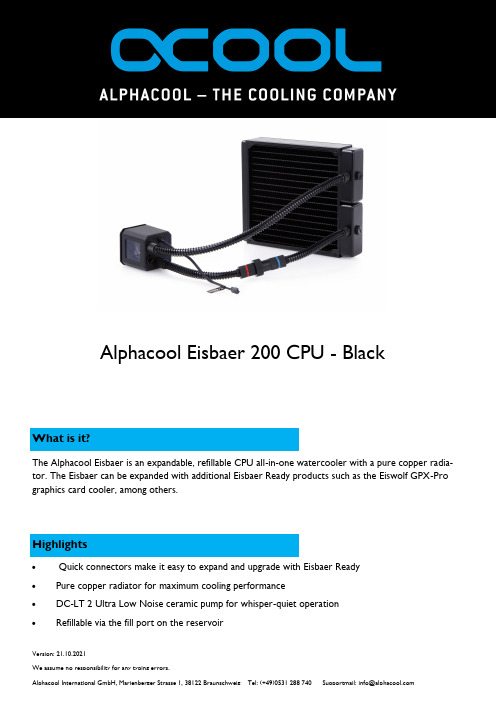
What is it?Alphacool Eisbaer 200 CPU - BlackHighlightsThe Alphacool Eisbaer is an expandable, refillable CPU all-in-one watercooler with a pure copper radia-tor. The Eisbaer can be expanded with additional Eisbaer Ready products such as the Eiswolf GPX-Pro graphics card cooler, among others.•Quick connectors make it easy to expand and upgrade with Eisbaer Ready• Pure copper radiator for maximum cooling performance• DC-LT 2 Ultra Low Noise ceramic pump for whisper-quiet operation •Refillable via the fill port on the reservoirArticle textWith the “Eisbaer”, Alphacool is fundamentally revolutionizing the AIO cooler market. Where traditional AIO CPU-coolers are disposable products which are neither upgradeable nor refillable, the Alphacool “Eisbaer” is modularly built and can be upgraded, rebuilt or refilled at any time. This means that the “Eisbaer” is not only an AIO, but also fully built on classic water cooling components. That means it is quieter and more powerful than the average AIO solution.RadiatorAlphacool depends on a radiator made of pure copper. The base of the radiator is the popular Alphacool NexXxoS series, which is well-loved around the world. The pure copper construction raises the cooling performance enormously compared to the usual aluminium radiators used in classic AIOs. The slight thickness of the fins ensures enormous cooling power in fans with low rotational speed. This ensures that the performance of the “Eisbaer” when adjusting the fans down decreases much more slowly than in radi-ators with higher fin thickness.HosesThe flexible PVC hoses make installing the “Eisbaer” easy. These hoses are easier to arrange and move into the right position. So the hoses don’t bend and stop the flow of the water, both hoses have been fit-ted with anti-kink springs. The 11/8 mm size is also a standard in the water cooling field, alongside the13/10 and 16/10.Quick-lock closureThe “Eisbaer” was designed with expandability directly in mind. This is why you’ll find a quick-lock closure on one of the hoses. This quick-lock mechanism is compatible with Alphacool HF quick-lock closures (1010383, 1010394, 1010395, 1010442), with which the circuit can easily be expanded to include anything from a radiator to a graphics card cooler. Furthermore, the “Eisbaer” is compatible with the upcoming Alphacool GPX-Pro graphics card AIO, which will use identical quick-lock closures.ConnectorsAll connectors are based on the classic G1/4 inch thread, the standard thread in the water cooling field. This way, all attachments can be switched out for others any time as desired. This also means that, for example, you could later decide to switch to thicker hoses or even HardTubes and set your system uniquely apart.All these features make the “Eisbaer” cooler into something extraordinary. Its enhanced appearance from the illuminated logo and the illuminated reservoir, which also contains the pump, lets the interior of your PC shine in a whole new way. The soft-touch surface of the pump case is a further visual highlight.With the “Eisbaer”, you get an all-around perfect product that is not only extremely high-powered but also works very quietly.PumpsThe basis of the pumps is the Alphacool DC-LT 2 Ceramic, also available separately. The pump runs ex-tremely quietly and can be regulated to between 7 and 12V. It can also be regulated through the mother-board. If the “Eisbaer” is being run alone, the 7V setting will still have next to no performance loss, as shown in diverse test results. The insulated pump case further perfects the noise generation and ensures that vibrations are almost completely absorbed.The smooth and shiny polished copper base of the cooler ensures optimal heat absorption and can relay the heat over the fine slit structure of the cooler to the water quickly and efficiently.To operate the Alphacool Eisbaer 200 CPU - Black at least one 200 mm fan is required. There are NO fans included in delivery!。
EPIC 多用途封闭接触器 150A以上电源切换说明书

Multi Purpose EPIC ® Sealed Contactor -150+ Amp Power SwitchingRoHS Compliant , all date codesPatent PendingChassis level UL508 sized power terminals – No need for speciallyrouted power cables, special bus bars, or special lugsRugged EPIC ® Seal rated to 175°C - Same technology used foradvanced aerospace programs that reduces risk of fire or meltdown in over current conditionsHermetically Sealed - Designed to meet: UL1604 for Class I & II, Div 2 and Class III for use in hazardous locations, IP67 for temporary water immersion for 30 min, SAE J1171 - external ignition protection, and ISO8846 for protection against ignition around flammable gassesElectronics-free high efficiency coil – No EMI emissions or cross-talk on your system control powerBuilt-in coil suppression for DC coils - Saves engineering time and parts cost to add external coil suppressionStainless steel hardware and mounting inserts, for years of corrosion free serviceUL508 ambient compliant to 75°C but can operate continuously at 85°C with a higher terminal temperature rise of 60°C. Can also operate up to 125°C in special cases -contact GIGAVAC for details.Not position sensitive – can be mounted in any position for ease of installationElectrical life rating is based on resistive load with TBD maximum inductance in circuit. Because your application may be different, we suggest you test the contactor in your circuit to verify life is as required.End of life is defined as when the dielectric, insulation resistance or contact resistance exceeds the specifications listed.If your application requires a higher current rating, you may want to consider the GIGAVAC GX12 EPIC ® sealed contactor .Make & Break Resistive Currentwith 1/0 cable and 50° terminal temp riseContact Voltages & Life Cycle RatingsDC or 50/60 Hz AC24 V 48 V 72 V 120 V 350 V 750 V150A - (75° C Ambient) 1/150,000100,00040,00020,0007,500 1,200 125A - (75° C Ambient) 1/180,000120,00048,00024,0009,0001,440 100A - (75° C Ambient) 1/225,000150,00060,00030,00011,2501,800 75A - (75° C Ambient) 1/300,000200,00080,00040,00015,0002,400 50A - (75° C Ambient) 1/435,000290,000116,00058,00021,7503,480 30A - (75° C Ambient) 1/750,000500,000200,000100,00037,5006,000 20A - (75° C Ambient) 1/900,000600,000240,000120,00045,0007,200 225A - (50° C Ambient) 2/127,50085,00034,00017,0006,3751,020 Max Break A, 2 cycles (75° C Ambient) 1/2,500A 2,000A 1,500A 1,000A 900A 600A Max Make, 10 cycles (75° C Ambient) 1/1,400A1,100A800A600A500A350A1/ Assumes UL508 ratings with 1/0 cables, UL508 max ambient temperature of 75°C as shown, and max. UL508 terminaltemperature rise of 50°C.At 85°C ambient, contactor can also meet all of its 75°C specifications but the terminal temperature can rise can be up to 60°C, which is higher than the 50°C rise allowed by UL508 and can be higher than some cable insulation ratings.2/ Assumes UL508 ratings with 1/0 cables, at a lower 50°C UL508 ambient temperature, and max. UL508 terminal temperature rise of 50°C.If your application requires a higher current rating, you may want to consider the GIGAVAC GX12 EPIC ® sealed contactor.1/ Assumes UL508 ratings with 1/0 cables, ambient maximum UL 508 temperature of 75°C, and maximum UL508terminal temperature rise of 50°C. Contactor can also carry the higher current as shown for 50°C ambient, and meet all of the UL508 temperature rise requirements.At 85°C ambient, contactor can also meet all of its 75°C specifications but the terminal temperature can rise can be up to 60°C, which is higher than the 50°C rise allowed by UL508 and can be higher than some cable insulation ratings.The maximum terminal temperature rating of the contactor is 175°C, which means much higher currents than shown can be carried and switched. However, this temperature is much higher than most cable insulation ratings, which mean busbars must be used. Contact GIGAVAC for assistance for higher current applications using this contactor.2/ Rating consists of combined inrush + cranking current at the times specified, with 2 seconds off between cycles. This is higher current than is required for UL1107 for marine battery switches.75°C / 50°CCable size 1/1 / 0Continuous, UL508 Max 1/ 10 seconds (1 time) 100 Seconds (1 time) 300 Seconds (1 time)Amp Amp Amp Amp 150 / 225 375 / 560 240 / 360 200 / 300 Starter Carry – Inrush 250 ms (10 repeats 1/ 2/)Amp NA / 2,000 Starter Carry - Cranking 10 sec (10 repeats 1/ 2/)Amp NA / 500 Maximum terminal Temp, Continuous Deg C 175 Maximum terminal Temp, Intermittent Deg C 225Ratings are at worse case temperature extremes, except coil resistance and current are at 25ºC.1/ DC coils have built-in coil suppression. The use of additional external coil suppression can slow the release time andinvalidate the life cycle ratings, or can cause the contactor not to be able to interrupt the maximum current specified. If lower coil back EMF is required, please contact GIGAVAC for assistance.Nominal Volts12Vdc 24Vdc 48Vdc 72Vdc 120Vdc 120Vac, 50/60Hz 240Vac, 50/60HzCoil P/N Designation B C F H J K L Max Volts14285684140140280 Pick-up, Volts, Max 7.51528467272144 Hold, Volts, Min491828464692 Drop-Out, Volts, Min0.50.5 1.8 2.7 4.5 4.59 Coil Resistance @ 25ºC (Ohms ±10%)17853358502125N/A N/A Coil Current, mA, Max at nominal Voltage7002801509056TBD TBD Coil Back EMF (volts) - Built in suppression 1/5555100150288N/AN/A1/ Auxillary contact rating - 2A, 24Vdc Resistive load, 100,000 cycles.2/50 Mohms after life.3/ Contactor can operate up to 125°C in special cases -contact GIGAVAC for details.SpecificationsUnits Specifications Contact Arrangement (main)Form X SPST-NO Contact Arrangement (Auxilary) 1/Form C SPDT Mechanical Lifecycles 1 millionContact ResistanceMax @ rated carry current Typical @ rated carry current mohms mohms .4 .15 to .3Operate time, 25˚CClose (includes bounce) Max Close (includes bounce) Typical Bounce on close, MaxRelease time (includes arc time at max. break current) ms ms ms ms 20 13 7 12 Insulation ResistanceMohms 100 2/ Dielectric at sea level (leakage < 1mA)VRMS 2,500 ShockG’s peak 20 Vibration, Sinusoidal (500-2000 Hz peak)G’s 15Operating ambient Temp Range ˚C -55 to +85 3/ Storage ambient Temp Range ˚C -70 to +175 Weight, TypicalKg (Lb)0.50/(1.1)GX11C ACoil VoltageB = 12 Vdc, internal coil suppressionC = 24 Vdc, internal coil suppression F = 48 Vdc, internal coil suppression H = 72 Vdc, internal coil suppression J = 120 Vdc, internal coil suppression K = 115 VAC, 50/60 Hz L = 240 VAC, 50/60HzCoil TerminationA = Flying leads, 38 cm (15 in)B = Flying leads, 61 cm (24 in)C = Flying leads, 122 cm (48 in)Auxiliary Contact (same length as coil wire selection) Blank = None A = SPDTThe polarity of the power terminals was previously shown reverse from what is correct and what is now indicated. The polarity is important only for switching the "Maximum Break, 2 cycles" when the voltage is over100 Vdc.Application Information:1. WARNING - When using more than one lug on a power terminal, make sure the primary power is closest to thecontactor busbar, with the lower current lug on top, then the washer, then the lock washer, then the nut. Improper order can cause severe over-heating resulting in the possible melting of the connecting cable insulation.2. EPIC ® sealing technology3. Relay Schematics and FormsPower contactsAuxiliary contacts (optional)05/12/08GIGAVAC® - P.O. Box 4428 - Santa Barbara, CA 93140-4428 - ph +(805) 684-8401 - +(805) 755-2000fx +(805) 684-8402 - **************** - - ©Copyright 2003-2008 GIGAVAC, LLC.。
阿尔法冷 Eisbaer Pro Aurora 240 CPU AIO 水冷器说明书

The Alphacool Eisbaer Pro Aurora CPU AIO water cooler is a specialdevelopment for processors with particularly large CPU dies. Theseinclude the AMD Threadripper and Epyc processors and the Intel CPUs for the LGA 3647 and LGA 4189 socket.•Full copper radiator, Nickel-plated copper cooler •Virtually silent DC-LT 2 pump •Tube length 40 cm •Digital RGB illuminated cooler and 120 mm fanAMD: AM4 / AM5 / SP3 / SP6 / sWRX8 / TR4 / TR5Intel: LGA 1700 / LGA 2011 / LGA 2011-3 / LGA 3647 / LGA 4189V. 1.008 // 11.2023Alphacool Eisbaer Pro Aurora 240 CPU AIOAlphacool article number: 117721 x Mounting set for AMD TR4 / sTRX4 / SP31 x Mounting set for AMD AM41 x Mounting set for Intel 2011 / 2011-3 / 2066 1 x Mounting set for Intel 3647 Narrow & Square 1 x Mounting set for Intel LGA 41891 x Mounting set for Intel LGA 17008 x M3x5 case mounting screws8 x M3x30 fan screws 2 x 120 mm Aurora Rise fans1 x Y-Adaptor 4-Pin PWM1 x Digital RGB Controller1 x 3-Pin JST to 3-Pin 5V adaptor 1 x Thermal compound1 x Screw plug Tool1 x Allen keyThe Alphacool Eisbaer Pro Aurora CPU AIO water cooler is a special development for processors with particularly large CPU dies. These include the AMD Threadripper and Epyc processors and the Intel CPUs for the LGA 3647 and LGA 4189 socket.Large cooling surfaceThe cold plate bottom covers the entire surface of the respective processors. The area of the cooling fins exceeds all known processor cores with an area of around 55 x 42 mm. This ensures that all hotspots of a CPU are directly covered and thus optimally cooled. The cooling fins are 0.4 mm thick and also have an optimal distance of 0.4 mm between them. In total there are 58 cooling fins on the bottom of the cooler. The bottom of the cooler is only 3 mm thick, which allows the heat to reach the water and be dissipated as quickly as possible.Copper radiatorAs per usual with Alphacool, the radiators are made of copper. Alphacool is the first manufacturer worldwide to use copper for all water bearing components such as the antechambers, the cooling fins and the cooling channels to which the fins are soldered. The connection threads are made of brass for strength reasons. In addition, the cooling fins are only lightly painted. On closer inspection the copper shimmers through a little. A thick lacquer coating would result in a reduction of the cooling capacity. The fin density is at optimal 15FPI. Therefore the radiator works perfectly even at low airflow. A too high fin density would require fans with higher speed to achieve the same cooling capacity. A lower fin density would no longer benefit from fast rotating fans. So the golden mean was chosen.Real water coolingThe Eisbaer Pro Aurora consists almost entirely of actual water cooling components. The extremely robust and durable TPV hoses are used in the enterprise products for servers and workstations. The hose connections also come from the Enterprise series from Alphacool and use the standard G1/4". This makes the Eisbaer Pro Aurora fully compatible with all common water cooling products. The quick-release fastener allows easy expansion of the AIO with additional components. The most important of these are the prefilled radiators and the Eiswolf GPU AIO water cooling system.Fan and lightingThe entire Eisbaer Aurora Pro cooler is equipped with addressable digital RGB LEDs. This gives a real eye-catcher in the Case. The fan used is the Aurora Rise with 120mm. Due to the special blade design, the fan is extremely quiet and the addressable RGB LEDs provide brilliant illumination. The Alphacool Aurora Rise fan convinces with a max. statistical pressure of 3.17mm/H2O and offers a max. air flow of 119.8m3/h. The PWM control allows the fan to be controlled over a wide speed range. Inaddition, it offers a zero control. It can therefore be regulated down to 0 rpm and then starts with approx. 350 rpm. Of courseall Digital RGB LEDs can be controlled at will. Depending on the controller almost all effects are possible.How to connect everythingThe fans are normally controlled via a 4-pin PWM connector. An included Y-adapter for the fans makes it easy to connect them to the mainboard. This allows all fans to be controlled and regulated via one connector. Each fan has a 3-pin JST connector including Y-adapter for the LED illumination. This allows the fans to be connected directly together and can also be controlled simultaneously via a controller. For the connection to a typical 3-pin 5V connector a corresponding adapter is included. Alternatively, the included Digital RGB controller can be used. The pump of the Eisbaer Aurora uses a 3-pin Molex connector. This can also be connected to the mainboard.The Eisbaer Pro Aurora is a true multi-talent. Expandable, fully compatible with DIY water cooling components and it is the optimal solution for the most powerful processors on the market.。
- 1、下载文档前请自行甄别文档内容的完整性,平台不提供额外的编辑、内容补充、找答案等附加服务。
- 2、"仅部分预览"的文档,不可在线预览部分如存在完整性等问题,可反馈申请退款(可完整预览的文档不适用该条件!)。
- 3、如文档侵犯您的权益,请联系客服反馈,我们会尽快为您处理(人工客服工作时间:9:00-18:30)。
Buzzer
- 30oC to + 60oC (Less than 90%) Indoor Only Upright Only IP 65 19.6m/s2 (30Hz, Back and Forth:2h・Right to Left:2h・Up and Down:2h) More than 1MΩ at 500VDC between the terminals and the chassis 500VAC applied for 1min between terminals and chassis without breaking insulation
SPECIFICATIONS 5 tiers 4 tiers Model 3 tiers 2 tiers 1 tier Rated Voltage Operating Voltage Current Consumption Typ. Max. Power Consumption Operating Temperature Range (Relative Humidity) Location Mounting Direction Protection Rating Vibration Resistance Insulation Resistance Withstanding Voltage Flashing Rate Buzzer Sound Level Tone Luminous Intensity Mass (Tolerance ±10%) No.LCE-.02A-PDFF-EN-1_2 ● This product conforms to the CE requirements and shows the CE Marking. ● Recognized as a UL standard. (Standard No. UL508, File No. E215660) ● This product complies with the RoHS Directive (DIRECTIVE 2002/95/EC) Red 550 mcd 1 tier 0.52 kg Amber 730 mcd 2 tiers 0.55 kg Green 1290 mcd 3 tiers 0.58 kg Blue 210 mcd 4 tiers 0.61 kg White 400 mcd 5 tiers 0.64 kg LCE-502A LCE-402A LCE-302A LCE-202A LCE-102A 24V AC/DC (50/60Hz) Rated Voltage ±10% Per Unit Red Amber Green Blue White 27.2mA 21.8mA 22.8mA 34.2mA Red Per Unit Amber Green 32.0mA
SPECIFICATIONS 5 tiers 4 tiers Model 3 tiers 2 tiers 1 tier Rated Voltage Operating Voltage Current Consumption Typ. Max. Operating Temperature Range (Relative Humidity) Location Mounting Direction Protection Rating Vibration Resistance Insulation Resistance Withstanding Voltage Flashing Rate Buzzer Sound Level Tone Luminous Intensity Mass (Tolerance ±10%) No.LCE-.02AW-PDFE-EN-1_2 ● This product conforms to the CE requirements and shows the CE Marking. ● Recognized as a UL standard. (Standard No. UL508, File No. E215660) ● This product complies with the RoHS Directive (DIRECTIVE 2002/95/EC) Red 550 mcd 1 tier 0.16 kg Amber 730 mcd 2 tiers 0.19 kg Green 1290 mcd 3 tiers 0.22 kg Blue 210 mcd 4 tiers 0.25 kg White 400 mcd 5 tiers 0.28 kg LCE-502AW LCE-402AW LCE-302AW LCE-202AW LCE-102AW 24V AC/DC (50/60Hz) Rated Voltage ±10% Per Unit Red Amber Green Blue White 27.2mA 21.8mA 22.8mA 34.2mA 32.0mA
o
Buzzer 40.0mA 50.0mA
(In
o
- 30 C to + 60 C (Less than 90%) Indoor Only Upright Only IP 54 19.6m/s2 Vibration Resistance (30Hz, Back and Forth:2h・Right to Left:2h・Up and Down:2h) Insulation Resistance More than 1MΩ at 500VDC between the terminals and the chassis Withstanding Voltage 500VAC applied for 1min between terminals and chassis without breaking insulation 60 ±12 Flashes Per Minute Flashing Rate Volume Adjustment Range (1m from center of Buzzer with dB meter set at ‘A’ weight): Sound Max.: 85 ±4dB Buzzer Level Min.: 70 ±4dB Buzzer1: Fast Intermittent Buzzer2: Slow Intermittent Tone Red Amber Green Blue White Luminous Intensity 550 mcd 730 mcd 1290 mcd 210 mcd 400 mcd 1 tier 2 tiers 3 tiers 4 tiers 5 tiers Mass (Tolerance ±10%) 0.58 kg 0.61 kg 0.64 kg 0.67 kg 0.70 kg No.LCE-.02AFB-PDFG-EN-1_2 ● This product conforms to the CE requirements and shows the CE Marking. ● Recognized as a UL standard. (Standard No. UL508, File No. E215660) ● This product complies with the RoHS Directive (DIRECTIVE 2002/95/EC)
Buzzer
Buzzer Blue White 0.7W 0.5W o - 30 C to + 60oC (Less than 90%) Indoor Only Upright Only IP 54 19.6m/s2 (30Hz, Back and Forth:2h・Right to Left:2h・Up and Down:2h) More than 1MΩ at 500VDC between the terminals and the chassis 500VAC applied for 1min between terminals and chassis without breaking insulation
SPECIFICATIONS 5 tiers 4 tiers Model 3 tiers 2 tiers 1 tier Rated Voltage Operating Voltage Current Consumption Typ. Max. Operating Temperature Range (Relative Humidity) Location Mounting Direction Protection Rating LCE-502AFB LCE-402AFB LCE-302AFB LCE-202AFB LCE-102AFB 24V AC/DC (50/60Hz) Rated Voltage ±10% Per Unit Red Amber Green Blue White 27.2mA 21.8mA 22.8mA 34.2mA