Pressure Controls Solid Model List (STP)
ASPEN压力改变模块

66.0
求: 泵的出口压力、提供给流体的功率、泵所需要的轴
功率各是多少?
精选课件
17
Compr 压缩机模型
Compr 模型用于模拟四种单元设备
1. 多变离心压缩机(Polytropic Centrifugal Compressor)
2. 多变正排量压缩机(Polytropic Positive Displacement Compressor)
精选课件
34
Valve —— 阀门模型
阀门模型用来调节流体流经管路时的压降。
精选课件
35
阀门模型有三种应用方式(计算类型) 1. 绝热闪蒸到指定出口压力
Adiabatic flash for specified outlet pressure 2. 对指定出口压力计算阀门流量系数
Calculate valve flow coefficient for specified outlet pressure
精选课件
29
MCompr 多级压缩机模型
MCompr 模型用于模拟三种单元设备
1. 多级多变压缩机 (Multi-stage Polytropic Compressor)
2. 多级正排量压缩机 (Multi-stage Positive Displacement Compressor)
3. 多级等熵压缩机(Multi-stage Isentropic Compressor)
精选课件
30
MCompr 的模型参数有 • 级数 (Number of stages)
指定压缩机的级数。 • 压缩机模型 (Compressor model)
有六种计算模型供选用。 • 设定方式 (Specification type)
Pulsafeeder机械隔膜计量泵说明书
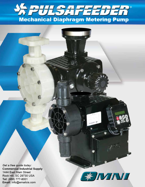
Get a free quote today:Commercial Industrial Supply 1444 East Main StreetRock Hill, SC 29730 USA Tel: (866) 777-8001Email: *****************Pulsafeeder ExpertiseSince 1936, Pulsafeeder has been the global leader in fluids handling technology and innovation in chemical dosing. Pulsafeeder has built a foundation of success with thousands of installations in fluid handling applications. Our extensive product breadth enables us to provide the convenience and efficiency of single-source solutions across various industries. 0912123135221008360002456831382669510.03.04.05.16.210.3180047675.7860160046.265.8175249435200114.9227.2422.710.36.25.13200845J K22 (5.8) 14 (3.8) 44(11.6) 28(7.5)75.7(20)49(13.0)102 (26.9) 66 (17.4)175 (46.2)113(30)128 (33.8) 83 (21.9)195 (51.5) 126 (33.4)249 (65.8) 161 (42.7)1300 (343) 843(222.6)1600 (423) 1037 (274.0)2600 (687) 1686 (445.3)3200 (845) 2074 (548.0)10.3 15010.3 15010.3 150 5.1 75 5.1 7510.3 15010.3 15010.3 150 4 60 4 60 4 60 4 6037 (24) 73 (47)125 (81) 73 (47)125 (81) 98 (64)146 (95)186 (121)146 (95)186 (121)146 (95)186 (121)0.18 0.250.18 0.250.18 0.250.18 0.250.18 0.250.37 0.50.37 0.50.37 0.51.1 1.51.1 1.51.1 1.51.1 1.550 Hz Flow LPH (GPH)Pressure SPM@ 50 Hz PowerModel1450 RPM940 RPMBar PSI1450 (940) RPM KW HP50HzJK26.5 (7) 17.5 (4.6) 53 (14) 35 (9.3) 91 (24) 60 (16)123 (32.4) 81 (21.4)212 (56) 140 (37)159 (42) 105 (27.7)246 (65) 163 (43) 313 (83) 207 (55)1440 (380) 952 (251)1800 (476) 1190 (314)2880 (761) 1903 (503)3600 (951) 2379 (638)10.3 15010.3 15010.3 150 5.1 75 5.1 7510.3 15010.3 15010.3 150 4 60 4 60 4 60 4 6044 (29) 88 (58)150 (99) 88 (58)150 (99)117 (77) 175 (116)223 (147)175 (116)223 (147)175 (116)223 (147)0.18 0.250.18 0.250.18 0.250.18 0.250.18 0.250.37 0.50.37 0.50.37 0.51.1 1.51.1 1.51.1 1.51.1 1.560 Hz Flow LPH (GPH)Pressure SPM@ 50 Hz PowerModel1725 RPM 1140 RPM Bar PSI 1725 (1140) RPM KW HP 60HzOMNI Series PumpsThe OMNI series is designed to be an economical, compact, rugged, simple, and reliable diaphragm metering pump. It features an industrial design to work in just about any application. OMNI series pumps are an outstanding choice for the customer looking for a simple and compact diaphragm metering pump. These reliable metering pumps are designed to perform in the widest range of chemical dosing applications.Product Specifications•Flows to 3600 l/h (951 GPH) at 60 Hz•Pressures to 10.3 Bar,(150 PSI)•Accuracy +/- 2% of flow•Temperatures to 65°C (150°F)•Viscosity up to 1000 CPS •Maximum 3m (10ft) NPSH •Maximum Suction Pressure 5 PSI or 0.4 bar less than design pressureMaterials of Construction•Head materials- PVDF, 316SS,or PP•Ball Valves - Ceramic or 316SS•Diaphragm - PTFE faced Hypalon on DC 2-4, solid PTFE on DC7Typical Applications•Acids •Caustics •Polymers •Bleaches •pH Control •Solvents •Dyes/Inks •Catalysts•Cleaning agents •And many moreOMNI ConfigurationsOMNI Series pumps are available in several configurations to meet any pumping challenge.Shown below: DC3, DC7 and DC7 Duplex.Mechanical Diaphragm TechnologyDiaphragm is mechanically attached to the reciprocating piston. The reciprocating diaphragm displaces controlled volume of process fluid through the suction and discharge valve mechanism.Benefits:•Eliminates hydraulic fluid•Simplifies commissioning and maintenance •Minimizes power requirements •Economical pumping solutionsCompletely non-vented Gearbox Design (DC7) prevents condensation and ingress of water and other containments. This provides exceptional durabiity and protection from the most extreme environments.Rugged Power Transmission Benefits:•Heavy duty worm gear is hardened and polished steel for DC7•DC2-DC4 worm gear is constructed of durable long life Bronze•Double shielded greased for life bearingsreduce your maintenanceSuction Stroke Discharge StrokeModel Specific QR CodePulsafeeder assists everyone in the field with information for THAT SPECIFIC PRODUCT , quickly and easily. No dedicated app needed. Simply use your QR Reader on your smart phone or tablet and scan the QR Code located on the Pulsafeeder product label, either Pump or Controller.•Identify - Model Number, Serial number, KOPkit (Repair Kit)•View - Quickly find product information such as parts list, IOM, tech sheet and more •Contact - Call or email Tech Support immediately to assist you•Email - Send this information to yourself or someone else, to save or even view laterFeatures & BenefitsController Ready•MPC controller option for DC 2-4•Handheld remote controller on pump or wall mounted •Display in LPH or GPHEasy to Install, Rugged Construction•Simple, intuitive design is easy to operate and maintain•Oil free, greased for life bearing with no more oil to buy or change (DC 2-4, DC7 has oil bath)•Compact and lightweight•Designed to withstand both indoor or outdoor rigors•Fan cooled motor design(when protected from precipitation and direct sunlight)Manual Stroke Adjustment Mechanism (DC2-4 only)•Simple, click in place manual adjustment•Lock mechanism to assure desired setting is maintained•Turndown capacity adjustable up to 1000:1 with MPC controlsCartridge Check Valves (DC2-4 only)•Guided ball check system reduces back flow and enhances priming characteristics•Simple o-ring seals provide for reliable leak free performance and easy replacementPatented Stroke Adjustment Mechanism (DC7 only)•Metering accuracy to +/-2% of flow •Provides full motion operation •Easy to read adjustment knobPatented Quick Change Check Valve System•Unique ball valve design is easy to access and very accurate •Stands up to wide range of acids, caustics and solvents•Completely inline accessible. No need to remove piping to service •Includes PVDF, PP & 316 SS materials(DC7 only)OMNI ComponentsReagent Head IEC & NEMA MotorcapableLightweight AluminiumCaseManual StrokeAdjustment withLock MechanismMechanicallyDriven HardenedSteel PistonDurable Heavy Duty DiaphragmHypalon Backed TFE/Teflon FaceCartridge CheckValvesDC2-4ReagentHeadPatentedQuick Change Check Valve System Durable Heavy Duty DiaphragmPTFE Disk DiaphragmMechanicallyDriven HardenedSteel PistonPatented Full MotionStroke AdjustmentMechanismLightweight AluminiumCaseDC7IEC & NEMA Motor capableControl OptionsMetering Pump Controller(Models DC 2-4 only)•Automatically controls and displays flow with a 4-20 mA input, handheld keypad, and manual stroke control•Controls Pulsafeeder metering pumps up to 1000:1 turn down ratio•The IP56 (NEMA 4X) Handheld user inter face is attached to the pump with 4.5 feet (1.5 meters ) of cable•Optionally, the Handheld can be mounted up to 1000 feet (304 meters) away from the pump•Handheld displays flow rate of the pump in LPH or GPH•Use digital inputs and outputs to monitor and control :•Supply tank level•Pump flow verification•Remote status indication of pump (on/off)•Pump alarm status•Pump auto/manual statusFor high technology in a simple to understand package at an economical price, add an MPC to the OMNI pump to take advantage of a complete system integration between metering pump and process.SystemsWhen used in a system, the OMNI Pump can be used in applications such as:•Water Conditioning Service-Chlorination •Water Treatment Service-Odor Control •Wastewater Service-Polymer Injection •Process pH Treatment-Acids & Caustics •Process Water-Corrosion InhibitorBack Pressure Valves provide positive back pressure for systems with less than the minimum required pressure difference between the discharge and suction side of the metering pump to assure best metering performance.Parts & AccessoriesCalibration ColumnsThese columns are constructed of clear PVC tubes with PVC end caps or an option for Borosilicate glass with Teflon end caps and should be sidedfor a 30-second draw down.Pressure Gauges are relied on to measure pressure in the system. Proper pressure is necessary to insure flow. Pulsafeeder Pressure Gaugesare accurate and reliable.A KOPkit (Keep On Pumping) can help you cut downtime and put you back in business fast. Use KOPkits for preventive maintenance and to ensure continuous high performance from your Pulsafeeder meteringpump.Pulsafeeder’s Pulsation Dampeners improve pump system efficiency by removing pulsating flows from positive displacement pumps.PulsaLube is the only oil Pulsafeeder recommends for use in metering and transfer pumps. Pulsalube is a superior blend of oils designed to provide optimal lubrication and extend equipment life.prevent anoverpressurizationsituation from ever damaging your pumps or pipes. Overpressurization can occur when a valve is closed or a blockage occurs. They are always recommended equipment for any pump or skid system.Pressure Relief Valves OMS001 C15。
Moldflow常用英语

33.Occurrence number
34.出现次数
35.Flow
36.流动
37.Cool
38.冷却
39.Gate location
40.浇口位置
41.Mold temperature
42.模具温度
43.New project
44.创建新项目
45.Export
46.导出
anize project
326.平均速率
327.Shear rate
328.剪切速率
329.Grow from
330.成型材料来源浇口(多浇口)
331.Clamp force centric
332.锁模力质心
333.Weld lines
334.熔接线
335.Air traps
336.气穴
337.Throughout
338.浇注系统流量
258.查找数据库
259.Edit default properties database
260.编辑数据库默认属性
261.Import legacy moldflow database
262.导入老版本Moldflow数据库
263.Import legacy C-mold database
264.导入老版本C-mold数据库
62.框选
63.Inclosing items only
64.选择被框选单元双面部分
65.Facing items only
66.选择被框选单元面对用户的部分
67.Study notes
68.案例记事本
69.Copy image to clipboard
70.复制图片到剪贴板
PTR LTR系列压力控制阀舱部分维护指南和零件清单说明书

PM-PTR/LTR-CWadsworth, Ohio 44281October 27, 1993Rev. October 1999PTR/LTR Series ActuatorsMaintenance Instructions & Parts List Provide Model Number and Serial Number When Ordering Spare Parts.The PTR/LTR Series Actuators will provide superior performance in heavy duty pneumatic and medium duty hydraulic applications. The new PTR Series "Wear-Tek" and LTR Series "Wear-Pak" piston sealing configurations and anti-friction ball bearings are used to guarantee low breakaway pressure and eliminate erratic motion at low speeds.In the event that maintenance is required, the following steps should be used as a guide. It is recommendedthat a suitable oil or O-ring lubrication compatible with the operating media, such as Parker Lube-A-Cyl, be used on all seals and mating parts to facilitate assembly.A.Inspection & Replacement of Piston Seal, #10, Wear Rings, #15, and O-Ring End Cap, #12.1.Remove Tie Rod Nuts, #17 from Tie Rods,#8.2.Pull End Cap, #16 free from Cylinder Tube, #14.3.Pull Cylinder Tube, #14 free from Housing, #13.4.Push Piston, #11 free from Cylinder Tube, #14.5.Inspect and/or replace Piston Seal, #10, Wear Rings, #15, and O-Ring End Cap, #12.6.Inspect and/or replace O-Ring Cylinder, #7 (for LTR Models only).7.Reassemble as shown in figure and torque Tie Rod Nuts, #17 per Torque Table.B.Inspection & Replacement of Bearing, #2.1.Remove Retaining Ring, #1.2.Press Pinion, #3, and Bearing #2 from housing, #13.3.Press Bearing, #2 free from Pinion, #3.4.Inspect or replace Bearing, #2.5.Press new Bearing, #2 into Housing, #13.6.Replace Pinion, #3 into Housing, #13.7.Press remaining new Bearing, #2 onto Pinion, #3.8.Replace Retaining Ring, #1.NOTE:Prior to assembly of an LTR Series actuator, the rack and pinion are coated with a molycoat GN paste and a moly grease containing a minimum MSOcontent of 3%, such as Texaco Molytex EP2.2The PTR Series actuator's rack, pinion and seals are coated with Parker Lube-A-Cyl prior to assembly.Add lubrication as required.12BUMPER OPTIONBuilt in polyurethane bumper pads absorb shock and noise,thus permitting faster cycle times and increased production rates. Recommended torque value for Bumper Bolt, item #19, is shown in Torque Table.All items marked with an asterick (*) are included in a complete seal kit.¹=Only used on units with steel cylinder tubes. (LTR units)x =Quantity as required per end cap option specified.3Built in meter-out flow controls provide for precise regulation of actuator speed and eliminate the cost and space ofexternally mounted components. A separate spring loaded ball check is used to provide free flow in the opposite direction.When both cushions and port flow controls are specified they will be stamped "C" and "P" respectively.To Adjust:Using an Allen wrench, turn Adjustment Screw, #29, clock-wise for slower speed; counterclockwise for more speed.SchematicPORT FLOW CONTROL OPTIONNOTE:Quantities shown are as required per end cap option specified.¹=Cushion seal configuration for use with pneumatic service.²=Cushion bushing for use with hydraulic service.CUSHION OPTION4STROKE ADJUST OPTIONS30° STROKE ADJUST OPTION WITH BUMPER30° STROKE ADJUST OPTION10° STROKE ADJUSTMENT WITH CUSHION OPTION NOTE:Quantities shown are as required per end cap option specified.Stroke adjusters will reduce the angle of rotation by 10° or 30° in either or both directions. Typical applications are for initial set up purposes where exact rotation requirements may change between various operations.CAUTION: Before making any adjustments, turn off systempressure and ensure that no residual pressure exists in the actuator.Standard cushions operate over the last 30° of rotation.Stroke adjusters will decrease the cushion length by the same amount. For example, reducing the rotation by 5°yields 25° cushion length.To Adjust:1.Loosen Jam Nut, #40.2.Turn Stroke Adjuster, #41 clockwise to reduce stroke,counterclockwise to increase stroke.3.Tighten Jam Nut, #40.4.Resume system pressure.MOUNTING OPTIONS Array Mounting options utilize existing face and base mountingholes.Shaft seal covers are designed to prolong bearing life by isolating them from external contamination and pressure.NOTE:1 = Quantity is 2 if double-end shaft extension isspecified.2 = Quantity is 0 if double-end shaft extension isspecified.(-) BLACK56HALL EFFECT SWITCH OPTIONLOW VOLTAGE DC SWITCH (10-30 VDC)Wiring Diagram and InformationHIGH VOLTAGE SWITCH (20-230 VAC/DC)Wiring Diagram and InformationAC White (3)Black (2)Internally Short Circuit ProtectedBrad Harrison 40909 Connector1. Green2. Black3. WhiteSWL1L2Pin ReceptacleDC Color CodeSWSource (PNP)Sink (NPN)(+)(-)3Pin ReceptacleAC Color Code2123451. White: +10 to 30 VDC2. Red: Source3. Ground Not Connected Nor Required (Green)4. Orange: Sink5. Black: CommonBrad Harrison 41310 Connector1White (1)Orange (4)Black (5)Red (2)NOTES:1.Available with or without cushions.2.Not available with stroke adjusters.3.Pressure rating: 1500 psi4.Operating temperature: -4°F to 158°F5.Specify switch type, orientation and voltage when ordering.6.Not available on PTR/LTR 10 size units.7.The low voltage DC switch is available in non-rotatable styleonly; consult representative for further information.The inductive type proximity switch provides end of rotation indication.The non-contact probe senses the presence of the ferrous cushion spear and has no springs, plungers, cams or dynamic seals that can wear out or go out of adjustment. The switch is solid state and meets NEMA 1, 12 & 13 specifications. For ease of wiring the connector housing is rotatable through 360°. To rotate, lift the cover latch,position, and release.*The standard proximity switch controls 20-230 VAC/DC loads from 5 to 500 mA. The low 1.7 mA off-state leakage current can allow use for direct PLC input. The standard short circuit protection (SCP) protects the switch from a short in the load or line upon sensing such a condition (5 amp or greater current) by assuming a non-conductive mode. The fault condition must be corrected and the power removed to reset the switch preventing automatic restarts.The low voltage DC switch is also available for use with 10-30 VDC.This switch is in a non-rotatable housing, but does incorporate the short circuit protection.Both switches are equipped with two LEDs, "Ready" and "Target". The "Ready" LED is lit when power is applied and the cushion spear is not present. The "Target" LED will light and the "Ready" LED will go out when the switch is closed, indicating the presence of the cushion spear.Both LEDs flashing indicates a short circuit condition.PROXIMITY SWITCHES* When connecting Inductive Load (relay, electromagnetic valve etc.) it is recommendedconnection shown)NOTE:Quantities shown are as required per end cap option specified.SPECIFICATIONS Type:Solid State Type (PNP or NPN)Switching Logic:Normally Open Supply Voltage Range: 5 - 30VDCCurrent Output Range:Up to100 mA at 5 VDC,Up to 200 mA at 12 VDC and 24 VDC Current Consumption:7 mA at 5 VDC, 15 mA at 12 VDC,and 30 mA at 24 VDC Switching Response:1000 Hz Maximum Residual Voltage: 1.5V Maximum Leakage Current:10uA MaximumBreakdown Voltage: 1.8kVACrms for 1 sec., lead to case Min. Current for LED:1mAOperating Temperature:14° to 140° F (-10° to 60° C)Lead Wire Length:39 inches (1meter)NPN WIRING CONNECTIONPNP WIRING CONNECTIONQuick ConnectOption1 Brown3 Blue4 Black78。
isysNet 24 VDC输出模块系列A(PSST8M23A、PSST8M12A、PSST8M8A

IntroductionFollow these instructions when installing, operating, or servicing the product.isysNet 24 VDC Output Modules, Series A (PSST8M23A, PSST8M12A, PSST8M8A)The sealed IP67 housing of these modules requires no enclosure. (Note that environmental requirements other than IP67 may require an additional appropriate housing.) I/O connectors are sealed M8 (pico) or M12 (micro) or M23 styles. The mounting base ships with the module. The PSST8M23A, PSST8M12A, and PSST8M8A modules are shown below.Installation & Service Instructions E107PisysNet 24 VDC Output Modules, Series A (PSST8M23A, PSST8M12A, PSST8M8A)ISSUED: December, 2006 Supersedes: June, 2005Doc.# E107P, EN# 060961, Rev. 2Pneumatic Division Richland, Michigan 49083Female M23FemaleConnectorM12-CFemaleConnectorM12-AFemaleConnectorM8-AFemaleConnectorM8-GFemaleConnectorM8-EFemaleConnectorM8-C!WARNINGFAILURE OR IMPROPER SELECTION OR IMPROPER USE OF THEPRODUCTS AND/OR SYSTEMS DESCRIBED HEREIN OR RELATEDITEMS CAN CAUSE DEATH, PERSONAL INJURY AND PROPERTYDAMAGE.This document and other information from Parker Hannifin Corporation,its subsidiaries and authorized distributors provide product and/or systemoptions for further investigation by users having technical expertise. Itis important that you analyze all aspects of your application, includingconsequences of any failure and review the information concerning theproduct or systems in the current product catalog. Due to the variety ofoperating conditions and applications for these products or systems, theuser, through its own analysis and testing, is solely responsible for makingthe final selection of the products and systems and assuring that allperformance, safety and warning requirements of the application are met.The products described herein, including without limitation, product features,specifications, designs, availability and pricing, are subject to change byParker Hannifin Corporation and its subsidiaries at any time without notice.EXTRA COPIES OF THESE INSTRUCTIONS ARE AVAILABLE FOR INCLUSIONIN EQUIPMENT / MAINTENANCE MANUALS THAT UTILIZE THESE PRODUCTS.CONTACT YOUR LOCAL REPRESENTATIVE.WARNINGTo avoid unpredictable system behavior that can cause personal injury and property damage:• Disconnect electrical supply (when necessary) before installation, servicing, or conversion.• Disconnect air supply and depressurize all air lines connected to this product before installation, servicing, or conversion.• Operate within the manufacturer’s specified pressure, temperature, and other conditions listed in these instructions.• Medium must be moisture-free if ambient temperature is below freezing.• Service according to procedures listed in these instructions.• Installation, service, and conversion of these products must be performed by knowledgeable personnel who understand how pneumatic products are to be applied.• After installation, servicing, or conversion, air and electrical supplies (when necessary) should be connected and the product tested for proper function and leakage. If audible leakage is present, or the product does not operate properly, do not put into use.• Warnings and specifications on the product should not be covered by paint, etc. If masking is not possible, contact your local representative for replacement labels.!Safety GuideFor more complete information on recommended application guidelines, see the Safety Guide section of Pneumatic Division catalogs or you can download the Pneumatic Division Safety Guide at: /safetyisysNet 24 VDC Output Modules, Series A (PSST8M23A, PSST8M12A, PSST8M8A) E107P2Important User InformationSolid state equipment has operational characteristics differing from those of electromechanical equipment. Safety Guidelines for the Application, Installation and Maintenance of Solid State Controls (available online at /pneu/isysNet) describes some important differences between solid state equipment and hard-wired electromechanical devices. Because of this difference, and also because of the wide variety of uses for solid state equipment, all persons responsible for applying this equipment must satisfy themselves that each intended application of this equipment is acceptable.In no event will Parker Hannifin Corporation be responsible or liable for indirect or consequential damages resulting from the use or application of this equipment.The examples and diagrams in this manual are included solely for illustrative purposes. Because of the many variables and requirements associated with any particular installation, Parker Hannifin Corporation cannot assume responsibility or liability for actual use based on the examples and diagrams.No patent liability is assumed by Parker Hannifin Corporation with respect to use of information, circuits, equipment, or software described in this manual.Reproduction of the contents of this manual, in whole or in part, without written permission of Parker Hannifin Corporation is prohibited.Throughout this manual we use notes to make you aware of safety considerations.isysNet 24 VDC Output Modules, Series A (PSST8M23A, PSST8M12A, PSST8M8A) E107P3Mount the I/O BaseT o mount the I/O base on a wall or panel, use the screw holes provided in the base.A mounting illustration for the base with an adapter is shown below.(137.0)for M4 Screw(76.6)for M6 ScrewKeyswitch- modulesInstall the Mounting Base as Follows:1. Lay out the required points as shown above in the drillingdimension drawing.2. Drill the necessary holes for #8 (M4) machine or self-tappingscrews.3. Mount the base using #8 (M4) screws.4. Ground the system using the ground lug connection. (The groundlug connection is also a mounting hole.)* Depending on the type and number of manifolds, this dimension may vary. Refer to Catalog 0600P-# for additional information.isysNet 24 VDC Output Modules, Series A (PSST8M23A, PSST8M12A, PSST8M8A) E107P Install the Digital Output ModuleTo Install the Digital Output Module, Proceed as Follows:1. Using a bladed screwdriver, rotate the keyswitch on the mountingbase clockwise until the number 1 aligns with the notch in thebase.2. Position the module vertically above the mounting base. Themodule will bridge two bases.3. Push the module down until it engages the latching mechanism. Y ouwill hear a clicking sound when the module is properly engaged.The locking mechanism will lock the module to the base.Remove the Digital Output Module From theMounting BaseTo Remove the Module from the Mounting Base:1. Put a flat blade screwdriver into the slot of the orange latchingmechanism.2. Push the screwdriver toward the I/O module to disengage thelatch. The module will lift up off the base.3. Pull the module off of the base.4isysNet 24 VDC Output Modules, Series A (PSST8M23A, PSST8M12A, PSST8M8A) E107P5Wire the Output ModulesFollowing are wiring instructions for the digital output modules.(view into connector)Pin 1 - Output 0 Pin 7 - Output 6Pin 2 - Output 1 Pin 8 - Output 7Pin 3 - Output 2 Pin 9 - Return (Com)Pin 4 - Output 3 Pin 10 - Return (Com)Pin 5 - Output 4 Pin 11 - 24VDC Pin 6 - Output 5Pin 12 - Chassis854113210126197PSST8M23A(view into connector)Pin 1 - 24VDC Pin 3 - CommonPin 4 - Output 0 (M8-A)Output 1 (M8-B) Output 2 (M8-C) Output 3 (M8-D) Output 4 (M8-E) Output 5 (M8-F) Output 6 (M8-G) Output 7 (M8-H)PSST8M8A(view into connector)Pin 1 - 24VDCPin 2 - Output 1 (M12-A) Pin 4 - Output 0 (M12-A)Output 3 (M12-B) Output 2 (M12-B)Output 5 (M12-C) Output 4 (M12-C) Output 7 (M12-D) Output 6 (M12-D)Pin 3 - CommonPin 5 - No ConnectPSST8M12ACommunicate With Your ModuleI/O messages are sent to (consumed) and received from (produced)the I/O modules. These messages are mapped into the processor’s memory. These I/O output modules produce 1 byte of input data (scanner Rx - status). They consume 1 byte of I/O data (scanner Tx).Default Data Map for the Output Modules PSST8M23A, PSST8M12A, PSST8M8A Message Size: 1 Byte7654321Produces Ch7 Ch6 Ch5 Ch4 Ch3 Ch2 Ch1 Ch0 Channel (Scanner Rx) Status Consumes Ch7 Ch6 Ch5 Ch4 Ch3 Ch2 Ch1 Ch0 Output (Scanner Tx) State Where: Channel Status 0 = no error, 1 = error; Output State 0 = OFF , 1 = ONEDS File RequirementsThe EDS files are available online at /pneu/isysnet.isysNet 24 VDC Output Modules, Series A (PSST8M23A, PSST8M12A, PSST8M8A) E107P6If your RSLogic 5000 is Version 15.X or greater:• Choose the PSST8M12A module from the list of Parker modules.• Enter a name and click OK.• N otice that the PSST8M12A is now under the I/O configuration.Add 24 VDC Output Modules to RSLogix 5000 I/O ConfigurationT o add your output modules to RSLogix 5000 I/O configuration,follow these steps:• In RSLogix 5000:- For ControlNet, highlight the PSSCCNA or 1738-ACNR (Shown), right click and select New Module.- For EtherNet/IP, highlight the PSSCENA or 1738-AENT (Shown), right click and select New Module.isysNet 24 VDC Output Modules, Series A (PSST8M23A, PSST8M12A, PSST8M8A) E107P7Troubleshoot With the IndicatorsIndication Probable CauseNetwork StatusOff Device is not on line:- Device has not completeddup_MAC-id test.- Device not powered - check modulestatus indicator.Flashing Green Device is on line but has noconnections in the established state. Green Device is on line and hasconnections in the established state. Flashing Red One or more I/O connections intimed-out state.Red Critical link failure - failedcommunication device. Devicedetected error that prevents it fromcommunicating on the network. Flashing Red/Green Communication faulted device - thedevice has detected a network accesserror and is in communication faultedstate. Device has received and acceptedan Identity Communication FaultedRequest - long protocol message. Indication Probable CauseI/O StatusOff Output is inactiveY ellow Output is active and under control Flashing Red Open circuit detection. No load.(Off-State only)Red Short circuit detected. (On-State only) Indication Probable CauseModule StatusOff No power applied to deviceGreen Device operating normallyFlashing Green Device needs commissioning due tomissing, incomplete, or incorrectconfigurationFlashing Red Recoverable faultRed Unrecoverable fault -may require device replacementFlashing Red/Green Device is in self-testIf your RSLogic 5000 is Version 13.X:• Choose the equivalent Rockwell Automation module from the listof modules.isysNet ModulesEquivalent Rockwell Automation1738 ArmorPoint ModulesPSST8M8A1738-OB8EM8PSST8M12A1738-OB8EM12PSST8M23A1738-OB8EM23** 1738-OB8EM23 profile will be available in RSLogix 5000 v15.T o use 1738-OB8EM23 in RSLogix 5000 v13, choose1738-OB8EM12 profile and disable keying.• Enter a name (optional), slot number, and communication format.Make sure to choose Compatible Module for Electronic Keyingsetting.• Choose Next to set RPI.• Choose Finish. Notice that the output module is now under theI/O configurationisysNet 24 VDC Output Modules, Series A (PSST8M23A, PSST8M12A, PSST8M8A) E107P8Digital Output Modules Outputs per Module8 (1 group of 8) nonisolated, sourcing Voltage Drop, On-State Output, Maximum 0.2VDC (sourcing modules) 0.7VDC (sinking module)Voltage, Off-State Output, Maximum 28.8VDCVoltage, On-State Output, Maximum Minimum Nominal28.8VDC 10VDC 24VDC Current Leakage, Off-State Output, Maximum 0.5 mACurrent, On-State Output Minimum 1.0 mA per channelOutput Current Rating1.0 A per channel, not to exceed 3.0 A maximum per module Output Delay Time OFF to ON, Maximum 10.1 ms Output Delay Time, ON to OFF , Maximum 10.1 ms Output Point Density2, 4, 8Output Surge Current, Maximum 2 A for 10 ms, repeatable every 3 seconds External DC Power Supply Current32 mAExternal DC Power Supply Voltage Range 10 to 28.8VDC External DC Power Supply Voltage Nominal 24VDC Keyswitch Position 1LED Indicators2, 4, or 8 yellow/red output status, logic side 1 green/red network status, logic side 1 green/red module status, logic side PointBus Current, Maximum 75 mA @ 5VDCPower Dissipation, Maximum *******************Thermal Dissipation, Maximum PSST8M-6.8BTU/***********Isolation Voltage(continuous-voltage withstand rating)50V rmsTested at 1250VAC rms for 60s Dimensions (includes I/O module Inches and mounting base) (Millimeters) 4.72H x 2.82W x 1.65D (120H x 72W x 42D)Operating TemperatureIEC 60068-2-1 (Test Ad, Operating Cold),IEC 60068-2-2 (Test Bd, Operating Dry Heat),IEC 60068-2-14 (T est Nb, Operating Thermal Shock):-20 to 60°C (-4 to 140°F)Storage TemperatureIEC 60068-2-1 (Test Ab, Un-packaged Non-operating Cold),IEC 60068-2-2 (Test Bb, Un-packaged Non-operating Dry Heat),-40 to 85°C (-40 to 185°F)Relative Humidity IEC 60068-2-30 (T est Db, Un-packaged Non-operating Damp Heat):5 to 95% non-condensingShockIEC60068-2-27 (Test Ea, Unpackaged Shock):Operating 30g Non-operating 50gVibration IEC60068-2-6 (Test Fc, Operating):5g @ 10 to 500Hz ESD ImmunityIEC 61000-4-2:6kV contact discharges 8kV air discharges Radiated RF ImmunityIEC 61000-4-3:10V/m with 1kHz sine-wave 80%AM from 30MHz to 2000MHz 10V/m with 200Hz 50% Pulse 100%AM at 900Mhz 10V/m with 200Hz 50% Pulse 100%AM at 1890Mhz EFT/B ImmunityIEC 61000-4-4: ±3kV at 5kHz on signal portsSurge Transient Immunity IEC 61000-4-5: ±1kV line-line(DM) and ±2kV line-earth(CM) on signal ports Conducted RF Immunity IEC 61000-4-6: 10Vrms with 1kHz sine-wave 80%AM from 150kHz to 80MHz EmissionsCSPR 11: Group 1, Class AEnclosure Type RatingMeets IP65/66/67 (when marked)Mounting Base Screw Torque #8 screw, 7.5 in. lbs. in Aluminum, 16 in. lbs. in Steel Wiring Category 21 - on signal ports Weight Imperial (Metric)0.64 lb. (0.29 kg)Certifications:(when product is marked)c-UL-us UL Listed Industrial Control Equipment,certified for US and CanadaCE European Union 89/336/EEC EMC Directive, compliant with:EN 61000-6-4; Industrial Emissions EN 50082-2; Industrial ImmunityEN 61326; Meas./Control/Lab., Industrial Requirements EN 61000-6-2; Industrial ImmunityC- Tick Australian Radiocommunications Act, compliant with: AS/NZS CISPR 11;Industrial Emissions1. OFF to ON or ON to OFF delay is time from a valid output “on” or “off” signal to output energization or de-energization.2. Use this Conductor Category information for planning conductor routing. Refer to Publication E115P , “Industrial Automation Wiring and Grounding Guidelines”.Specifications - Following are specifications for the digital output modules.。
Abaqus单元选择压力接触和网格生成

学习改变命运,知 识创造未来
2021年3月4日星期四
内容提要
• Elements in ABAQUS • Structural Elements (Shells and Beams) vs. Continuum Elements • Modeling Bending Using Continuum Elements
学习改变命运,知 识创造未来
Abaqus单元选择压力接触和网格生成
Structural Elements (Shells and Beams) vs. Continuum Elements
学习改变命运,知 识创造未来
Abaqus单元选择压力接触和网格生成
Structural Elements (Shells and Beams) vs. Continuum Elements
• Reduced integration: 简缩积分
• The integration rule that is one order less than the full integration rule.
Full integration
Firstorder interpolation
Reduced integration
– ABAQUS/Standard includes many more variations within each element family.
– ABAQUS/Explicit 包括的单元绝大多数都为一次单元。 • 例外: 二次▲单元和四面体单元 and 二次 beam elements
– Many of the same general element selection guidelines apply to both programs.
HP原装颜色墨水卡车辆安全数据表说明书

SAFETY DATA SHEET1. Identification*** This Safety Data Sheet is only authorised for use by HP for HP Original products. Anyunauthorised use of this Safety Data Sheet is strictly prohibited and may result in legal actionbeing taken by HP. ***Important informationHP Color LaserJet CF412A-X-XC Yellow Print CartridgeProduct identifierNone.Other means of identificationThis product is a yellow toner preparation that is used in HP Color LaserJet Pro M452, HP ColorLaserJet Pro MFP M477, HP Color LaserJet Pro MFP M377 series printers.Recommended useNone known.Recommended restrictionsManufacturer/Importer/Supplier/Distributor informationHP Inc.1501 Page Mill RoadPalo Alto, CA 94304-1112United StatesTelephone650-857-1501HP Inc. health effects line(Toll-free within the US)1-800-457-4209(Direct)1-760-710-0048HP Inc. Customer CareLine(Toll-free within the US)1-800-474-6836(Direct)1-208-323-2551Email:2. Hazard(s) identificationNot classified.Physical hazardsNot classified.Health hazardsNot classified.Environmental hazardsNot classified.OSHA defined hazardsLabel elementsNone.Hazard symbolSignal word None.Hazard statement Not available.Precautionary statementPrevention Not available.Response Not available.Storage Not available.Disposal Not available.Hazard(s) not otherwise classified (HNOC)None of the other ingredients in this preparation are classified as carcinogens according to ACGIH, EU, IARC, MAK, NTP or OSHA.GHS Supplemental information This product is not classified as hazardous according to OSHA CFR 1910.1200 (HazCom 2012).3. Composition/information on ingredientsMixturesCAS number% Chemical name Common name and synonymsTrade Secret Styrene acrylate copolymer<85Pigment Trade Secret Pigment<10CAS number %Chemical name Common name and synonyms WaxTrade Secret Wax<10Amorphous silica7631-86-9Amorphous silica<34. First-aid measuresMove person to fresh air immediately. If irritation persists, consult a physician.Inhalation Wash affected areas thoroughly with mild soap and water. Get medical attention if irritation develops or persists.Skin contact Do not rub eyes. Immediately flush with large amounts of clean, warm water (low pressure) for at least 15 minutes or until particles are removed. If irritation persists, consult a physician.Eye contact Rinse mouth out with water. Drink one to two glasses of water. If symptoms occur, consult a physician.IngestionNot available.Most importantsymptoms/effects, acute and delayed5. Fire-fighting measuresCO2, water, or dry chemical Suitable extinguishing media None known.Unsuitable extinguishing mediaLike most organic material in powder form, toner can form explosive dust-air mixtures when finely dispersed in air.Specific hazards arising from the chemicalNot available.Special protective equipment and precautions for firefighters If fire occurs in the printer, treat as an electrical fire.Fire fightingequipment/instructions None established.Specific methods6. Accidental release measuresMinimize dust generation and accumulation.Personal precautions,protective equipment and emergency procedures Slowly vacuum or sweep the material into a bag or other sealed container. Clean remainder with a damp cloth or vacuum cleaner. If a vacuum is used, the motor must be rated as dustexplosion-proof. Fine powder can form explosive dust-air mixtures. Dispose of in compliance with federal, state, and local regulations.Methods and materials for containment and cleaning upDo not flush into surface water or sanitary sewer system. See also section 13 Disposal considerations.Environmental precautions7. Handling and storageKeep out of the reach of children. Avoid inhalation of dust and contact with skin and eyes. Use with adequate ventilation. Keep away from excessive heat, sparks, and open flames.Precautions for safe handling Keep out of the reach of children. Keep tightly closed and dry. Store at room temperature. Store away from strong oxidizers.Conditions for safe storage,including any incompatibilities8. Exposure controls/personal protectionOccupational exposure limitsUS. NIOSH: Pocket Guide to Chemical Hazards Value Components TypeTWA6 mg/m3Amorphous silica (CAS 7631-86-9)No biological exposure limits noted for the ingredient(s).Biological limit values USA OSHA (TWA/PEL): 15 mg/m3 (Total Dust), 5 mg/m3 (Respirable Fraction)ACGIH (TWA/TLV): 10 mg/m3 (Inhalable Particulate), 3 mg/m3 (Respirable Particulate)Amorphous silica: USA OSHA (TWA/PEL): 20 mppcf 80 (mg/m3)/%SiO2, ACGIH (TWA/TLV): 10mg/m3TRGS 900 (Luftgrenzwert) - 10 mg/m3 (Einatembare partikel), 3 mg/m3 (Alveolengängige fraktion)Exposure guidelinesUse in a well ventilated area.Appropriate engineeringcontrolsIndividual protection measures, such as personal protective equipmentNot available.Eye/face protectionSkin protectionNot available.Hand protectionNot available.OtherNot available.Respiratory protectionNot available.Thermal hazards9. Physical and chemical propertiesFine powderAppearanceSolid.Physical statesolidFormYellowColorSlight plastic odorOdorOdor threshold Not available.pH Not applicableMelting point/freezing point Not available.Not applicableInitial boiling point and boilingrangeFlash point Not applicableEvaporation rate Not applicableNot available.Flammability (solid, gas)Upper/lower flammability or explosive limitsNot flammableFlammability limit - lower(%)Not available.Flammability limit - upper(%)Explosive limit - lower (%)Not available.Explosive limit - upper (%)Not available.Vapor pressure Not applicableVapor density Not applicableSolubility(ies)Solubility (water)Negligible in water. Partially soluble in toluene and xylene.Not available.Partition coefficient(n-octanol/water)Auto-ignition temperature Not applicableDecomposition temperature> 392 °F (> 200 °C)Viscosity Not applicableOther informationNo information available.Oxidizing propertiesPercent volatile0 % estimatedSoftening point176 - 266 °F (80 - 130 °C)Specific gravity 1 - 1.210. Stability and reactivityNot available.ReactivityStable under normal storage conditions.Chemical stabilityWill not occur.Possibility of hazardousreactionsImaging Drum: Exposure to lightConditions to avoidStrong oxidizersIncompatible materialsCarbon monoxide and carbon dioxide.Hazardous decompositionproducts11. Toxicological informationInformation on likely routes of exposureInhalation Under normal conditions of intended use, this material is not expected to be an inhalation hazard.Skin contact Contact with skin may result in mild irritation.Eye contact Contact with eyes may result in mild irritation.Ingestion Ingestion is not a likely route of exposure.Not available.Symptoms related to thephysical, chemical andtoxicological characteristicsInformation on toxicological effectsAcute toxicity Based on available data, the classification criteria are not met.Based on available data, the classification criteria are not met.Skin corrosion/irritationBased on available data, the classification criteria are not met.Serious eye damage/eyeirritationRespiratory or skin sensitizationRespiratory sensitization Based on available data, the classification criteria are not met.Based on available data, the classification criteria are not met.Skin sensitizationNegative, does not indicate mutagenic potential (Ames Test: Salmonella typhimurium)Germ cell mutagenicityBased on available data, the classification criteria are not met.Carcinogenicity Based on available data, the classification criteria are not met.IARC Monographs. Overall Evaluation of CarcinogenicityNot listed.OSHA Specifically Regulated Substances (29 CFR 1910.1001-1050)Not regulated.US. National Toxicology Program (NTP) Report on CarcinogensNot listed.Based on available data, the classification criteria are not met.Reproductive toxicityBased on available data, the classification criteria are not met.Specific target organ toxicity -single exposureBased on available data, the classification criteria are not met.Specific target organ toxicity -repeated exposureAspiration hazard Based on available data, the classification criteria are not met.Further information Complete toxicity data are not available for this specific formulationRefer to Section 2 for potential health effects and Section 4 for first aid measures.12. Ecological informationLC50: > 100 mg/l, Fish, 96.00 HoursEcotoxicitySpeciesProduct Test ResultsCF412A-X-XCAquaticFish> 100 mg/l, 96 HoursFishLC50Not available.Persistence and degradabilityNot available.Bioaccumulative potentialNot available.Mobility in soilOther adverse effects Not available.13. Disposal considerationsDo not shred toner cartridge, unless dust-explosion prevention measures are taken. Finely Disposal instructionsdispersed particles may form explosive mixtures in air. Dispose of in compliance with federal,state, and local regulations.HP's Planet Partners (trademark) supplies recycling program enables simple, convenient recyclingof HP original inkjet and LaserJet supplies. For more information and to determine if this serviceis available in your location, please visit /recycle.14. Transport informationNot a dangerous good under DOT, IATA, ADR, IMDG, or RID.Further information15. Regulatory informationUS EPA TSCA Inventory: All chemical substances in this product comply with all rules or orders US federal regulationsunder TSCA.TSCA Section 12(b) Export Notification (40 CFR 707, Subpt. D)Not regulated.CERCLA Hazardous Substance List (40 CFR 302.4)Not listed.SARA 304 Emergency release notificationNot regulated.OSHA Specifically Regulated Substances (29 CFR 1910.1001-1050)Not regulated.Superfund Amendments and Reauthorization Act of 1986 (SARA)Immediate Hazard - NoHazard categoriesDelayed Hazard - NoFire Hazard - NoPressure Hazard - NoReactivity Hazard - NoSARA 302 Extremely hazardous substanceNot listed.NoSARA 311/312 HazardouschemicalOther federal regulationsClean Air Act (CAA) Section 112 Hazardous Air Pollutants (HAPs) ListNot regulated.Clean Air Act (CAA) Section 112(r) Accidental Release Prevention (40 CFR 68.130)Not regulated.Not regulated.Safe Drinking Water Act(SDWA)Not ListedUS state regulationsAll chemical substances in this HP product have been notified or are exempt from notification Regulatory informationunder chemical substances notification laws in the following countries: US (TSCA), EU(EINECS/ELINCS), Switzerland, Canada (DSL/NDSL), Australia, Japan, Philippines, South Korea,New Zealand, and China.16. Other information, including date of preparation or last revision16-Oct-2015Issue date02-Oct-2019Revision dateVersion #06This SDS was prepared in accordance with USA OSHA Hazard Communications regulation (29 Other informationCFR 1910.1200).This Safety Data Sheet document is provided without charge to customers of HP. Data is the most current known to HP at the time of preparation of this document and is believed to be accurate. It should not be construed as guaranteeing specific properties of the products as described or suitability for a particular application. This document was prepared to the requirements of the jurisdiction specified in Section 1 above and may not meet regulatory requirements in other countries.This safety data sheet is meant to convey information about HP inks (toners) provided in HP Original ink (toner) supplies. If our Safety Data Sheet has been provided to you with a refilled,remanufactured, compatible or other non-HP Original supply please be aware that the information contained herein was not meant to convey information about such products and there could be considerable differences from information in this document and the safety information for the product you purchased. Please contact the seller of the refilled, remanufactured or compatible supplies for applicable information, including information on personal protective equipment,exposure risks and safe handling guidance. HP does not accept refilled, remanufactured or compatible supplies in our recycling programs.DisclaimerIdentification: Important informationRevision information Explanation of abbreviationsACGIH CAS DOT EPCRA CERCLA CFR COC IARC NIOSH NTP OSHA PEL RCRA REC REL SARA STEL TCLP TLV TSCA VOCAmerican Conference of Governmental Industrial Hygienists Chemical Abstracts ServiceComprehensive Environmental Response Compensation and Liability Act Code of Federal Regulations Cleveland Open Cup Department of TransportationEmergency Planning and Community Right-to-Know Act (aka SARA)International Agency for Research on Cancer National Institute for Occupational Safety and Health National Toxicology ProgramOccupational Safety and Health Administration Permissible Exposure LimitResource Conservation and Recovery Act RecommendedRecommended Exposure LimitSuperfund Amendments and Reauthorization Act of 1986Short-Term Exposure LimitToxicity Characteristics Leaching Procedure Threshold Limit Value Toxic Substances Control Act Volatile Organic Compounds。
航空机械部件说明书

Installation Instructions Air Flow SwitchCatalog Number(s) 1414-CPN10APWAB,1414-CPN10APQAB, 1414-CPM10APWABAbout Air Flow Switch (AFS)The AFS is a general purpose airflow proving switch designed for HV AC and energy management applications. It may be used to sense positive, negative or differential air pressure.The plated housing contains a diaphragm, a calibration spring and a snap-acting SPDT (NC) switch.The sample connections located on each side of the diaphragm accept a .25” OD tubing via the integral compression and nut.An enclosure cover guards against accidental contact with the live switch terminal screws and the set point adjusting screw. The enclosure cover will accept a .5”conduit connection. The AFS (1414-CPM10APW AB) has a reset button located onthe top surface of the enclosure cover.Publication 1414-IN003A-EN-P - October 20052 Air Flow SwitchImportant User InformationSolid state equipment has operational characteristics differing from those of electromechanical equipment. Safety Guidelines for the Application, Installation and Maintenance of Solid State Controls (Publication SGI-1.1 available from your local Rockwell Automation sales office or online at) describes some important differences between solid state equipment and hard-wired electromechanical devices. Because of this difference, and also because of the wide variety of uses for solid state equipment, all persons responsible for applying this equipment must satisfy themselves that each intended application of this equipment is acceptable.In no event will Rockwell Automation, Inc. be responsible or liable for indirect or consequential damages resulting from the use or application of this equipment.The examples and diagrams in this manual are included solely for illustrative purposes. Because of the many variables and requirements associated with any particular installation, Rockwell Automation, Inc. cannot assume responsibility or liability for actual use based on the examples and diagrams.No patent liability is assumed by Rockwell Automation, Inc. with respect to use of information, circuits, equipment, or software described in this manual.Reproduction of the contents of this manual, in whole or in part, without written permission of Rockwell Automation, Inc., is prohibited.Throughout this manual, when necessary, we use notes to make you aware of safety considerations.Publication 1414-IN003A-EN-P - October 2005Air Flow Switch 3Publication 1414-IN003A-EN-P - October 2005Install Air Flow SwitchSelect a mounting location which is free from vibration. The AFS pressure switch MUST be mounted with the diaphragm in any vertical plane in order to obtain the lowest specified operating set point. Avoid mounting with the sample lineconnections in the “UP” position. Surface mount via the two 3/16” diameter holes in the integral mounting bracket. The mounting holes are 3 7/8” apart.Figure 1 DimensionsAir Sampling ConnectionThe AFS is designed to accept sample lines of .25” OD tubing by means of ferrule and nut compression connections. Locate the sampling probe a minimum of 1.5 duct diameters down stream from the air source. Install the sampling probe as close to the air stream as possible. The low pressure side is designated by the stamped ‘LOW’ on the housing of the diaphragm.•Positive Pressure Only: Connect the sample line to the LOW side and the HIGH side remains open to atmosphere.•Negative Pressure Only: Connect the sample line to the HIGH side and the LOW side remains open to atmosphere.•Two Negative Samples: Connect the higher negative sample to the HIGH side and the lower negative sample to the LOW side.•Two Positive Samples: Connect the higher positive sample to the LOW side and the lower positive sample to the HIGH side.•One Positive and One Negative Sample: Connect the positive sample to the LOW side and connect the negative sample to the HIGH side.4 Air Flow SwitchPublication 1414-IN003A-EN-P - October 2005Figure 2 Alarm or ControlField AdjustmentFrom lowest operating point several turns of the adjusting screw are necessary to engage the calibration spring. No change in set point will occur until the spring is engaged. For higher set points continue turning screw in a clockwise direction. It may be useful to connect a manometer in parallel with the switch when adjusting, as the final operating point can be noted for future reference. Please see specifications for actual ranges and set point information.SpecificationsAir Flow Switch SpecificationsSpecification 1414-CPN10APWAB 1414-CPN10APQAB 1414-CPM10APWAB Sample Media AirAirAirMounting Position Diaphragm in any vertical planeDiaphragm in any vertical plane Diaphragm in any vertical planeField Adjustable Range.05, ±.02” w.c. to 12” w.c..05, ±.02” w.c. to 2” w.c..40, ±.06” w.c. to 12” w.cSwitch DifferentialProgressive, increasing from approximately .02± .01” w.c. at minimum set point, to approximately .8” w.c. at maximum set point.Progressive, increasing from 0.02± 0.01” w.c. at minimum set point to approximately 0.1” w.c. at maximum set point.Progressive, increasing from approximately .06± .01” w.c. at minimum set point, to approximately .8”w.c. at maximum set point.Maximum Pressure .5” (0.03 bar).5” (0.03 bar).5” (0.03 bar)OperatingTemperature Range-40°C … 82.2°C (-40°F…180°F)-40°C … 82.2°C (-40°F…180°F)-40°C … 82.2°C (-40°F…180°F)Air Flow Switch 5Publication 1414-IN003A-EN-P - October 2005Life100,000 cycles/min. at 5psi max pressure each cycle and at max electrical load.100,000 cycles/min. at 5psi max pressure each cycle and at max electrical load.600 cycles/min. at 5psi max pressure each cycle and at max electrical load.Electrical Rating300 va pilot duty at 115…277vac, 10 amp, non-inductive, 277 vac, 60Hz.300 va pilot duty at 115…277vac, 10 amp, non-inductive, 277 vac, 60Hz.300 va pilot duty at 115…277vac, 10 amp, non-inductive, 277 vac, 60Hz.Contact Arrangement SPDTSPDTSPDTElectrical Connections Screw top terminals with cup washersScrew top terminals with cup washers Screw top terminals with cup washers Sample Line ConnectionsFerrule and nut compression typeconnectors that accept .25” OD rigid tubing.Ferrule and nut compression type connectors that accept .25” OD rigid tubing.Ferrule and nut compression type connectors that accept .25” OD rigid tubing.Automatic/Manual ResetAutomaticAutomaticManualAir Flow Switch SpecificationsSpecification 1414-CPN10APWAB 1414-CPN10APQAB 1414-CPM10APWAB6 Air Flow SwitchPublication 1414-IN003A-EN-P - October 2005Air Flow Switch 7 Publication 1414-IN003A-EN-P - October 2005All other trademarks are the property of their respective holders, and are hereby acknowledged.Publication 1414-IN003A-EN-P - October 2005PN 40055-233-01(1)Copyright © 2005 Rockwell Automation, Inc. All rights reserved. Printed in the U.S.A.。