STV5404E-001中文资料
苏州万龙ST500说明书

22、功能配置一览表保护模式下,A 继电器的触点(14#/15#)为常闭接点,一般串联在电动机控制接触器线圈回路中,但当控制器上电正常工作时,A 继电器立即得电吸合,仅在失电或发生故障保护后方再次断开。
注:①控制器内部矢量和的接地保护为标准配置,但漏电和接地保护只能二选一,当增选漏电时,接地保护功能自动退出。
②控制器不带通讯功能时型号为ST501,增选通讯功能时型号为ST502(Profibus-DP ),ST503(Modbus-RTU)S 500智能型电动机控制器保护模式方式使用说明书T33、控制器保护模式下的典型接线图保护模式下,控制器内A 继电器(14#、15#)常闭接点串在控制电机接触器的线圈回路中(CJ 接触器),在控制器得电工作时立即闭合,此时方允许电机工作;当过载等故障保护动作时A 继电器接点断开,控制电机接触器CJ 失电停车。
故障后需按一次复位按钮方可清除故障指示和故障接点信号,同时需等待电机热容冷却到允许再次起动值时,控制器内A 继电器才自动闭合,允许电机再次起动运行。
保护模式下控制器提供装置失电/自诊断、故障跳闸等故障接点输出(图中19、20、21),其中自诊断接点为常闭,控制器得电正常工作时为常开,当控制器自检到装置故障或失电时变为常闭。
故障跳闸接点为常开,只有当控制器检测到故障并按规定特性保护动作时变为常闭。
分析排除故障后需按复位按钮方可清除故障指示和故障接点信号。
保护模式下控制器可据用户需要增选电压功能、电动机绕组热保护功能、漏电保护功4、ST522显示模块在保护方式下,ST522操作显示模块作为增选附件可与ST500配合使用(通过T9**~02串口线连接),通过ST522可以实时显示电机的各种运行参数;调整各种参数(保护定值、系统参数);检查各种故障信息/报警信息/DI 和DO 状态;查询各种管理信息。
保护方式下的ST522面板功能定义如下:S 500智能型电动机控制器保护模式方式使用说明书T41:液晶显示屏2:指示灯3:功能键4.1指示灯运行指示当前电动机处于正常工作状态,允许电动机进行操作控制。
MM5ZxxxST1G Serie Zener Voltage Regulators 500 mW
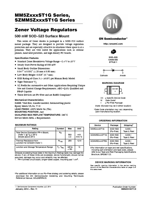
MM5ZxxxST1G Series, SZMM5ZxxxST1G Series Zener Voltage Regulators 500 mW SOD−523 Surface MountThis series of Zener diodes is packaged in a SOD−523 surface mount package. They are designed to provide voltage regulation protection and are especially attractive in situations where space is at a premium. They are well suited for applications such as cellular phones, hand held portables, and high density PC boards. Specification Features•Standard Zener Breakdown V oltage Range −2.4 V to 18 V •Steady State Power Rating of 500 mW•Small Body Outline Dimensions:0.047″ x 0.032″ (1.20 mm x 0.80 mm)•Low Body Height: 0.028″ (0.7 mm)•ESD Rating of Class 3 (> 16 kV) per Human Body Model •Tight Tolerance V Z•SZ Prefix for Automotive and Other Applications Requiring Unique Site and Control Change Requirements; AEC−Q101 Qualified and PPAP Capable•These Devices are Pb−Free and are RoHS Compliant*Mechanical CharacteristicsCASE:V oid-free, transfer-molded, thermosetting plasticEpoxy Meets UL 94, V−0LEAD FINISH: 100% Matte Sn (Tin)MOUNTING POSITION:AnyQUALIFIED MAX REFLOW TEMPERATURE: 260°CDevice Meets MSL 1 RequirementsMAXIMUM RATINGSRating Symbol Max UnitTotal Device Dissipation FR−4 Board, (Note 1) @ T A = 25°CDerate above 25°C P D5004.0mWmW/°CThermal Resistance from Junction−to−Ambient (Note 1)R q JA250°C/WJunction and Storage Temperature Range T J, T stg−65 to+150°CStresses exceeding those listed in the Maximum Ratings table may damage the device. If any of these limits are exceeded, device functionality should not be assumed, damage may occur and reliability may be affected.1.FR−4 printed circuit board, single−sided copper, mounting pad 1 cm2.*For additional information on our Pb−Free strategy and soldering details, please download the ON Semiconductor Soldering and Mounting Techniques Reference Manual, SOLDERRM/D.Device Package Shipping†ORDERING INFORMATIONCathode AnodeSee specific marking information in the device marking column of the Electrical Characteristics table on page 2 of this data sheet.DEVICE MARKING INFORMATIONSOD−523CASE 502STYLE 1MARKING DIAGRAMXX= Specific Device CodeM Date Code*G= Pb−Free Package(Note: Microdot may be in either location)*Date Code orientation may vary dependingupon manufacturing location.MM5ZxxxST1G SOD−523(Pb−Free)3,000 /Tape & Reel†For information on tape and reel specifications, including part orientation and tape sizes, please refer to our T ape and Reel Packaging Specifications Brochure, BRD8011/D.SOD−523(Pb−Free)SZMM5ZxxxST1G3,000 /Tape & ReelSOD−523(Pb−Free)SZMM5ZxxxST5G8,000 /Tape & ReelELECTRICAL CHARACTERISTICS (T A = 25°C unless otherwise noted,V F = 0.9 V Max. @ I F = 10 mA for all types) Symbol Parameter V Z Reverse Zener Voltage @ I ZTI ZT Reverse CurrentZZT Maximum Zener Impedance @ I ZTI ZK Reverse CurrentZ ZK Maximum Zener Impedance @ I ZKI R Reverse Leakage Current @ V RV R Reverse VoltageI F Forward CurrentV F Forward Voltage @ I FQ V Z Maximum Temperature Coefficient of V Z C Max. Capacitance @V R = 0 and f = 1 MHzV Figure 1. Zener Voltage RegulatorELECTRICAL CHARACTERISTICS (V F = 0.9 Max @ I F = 10 mA for all types)Device*DeviceMarkingTestCurrentIzt mAZener VoltageVZZ ZK I Z= 1.0mA WMaxZ ZTI Z = IZT@ 10%Mod WMaxMaxIR @ VRd VZ/dt (mV/k)@ I ZT1 = 5 mA C pF Max @V R = 0f = 1 MHzMin Max m A V Min MaxMM5Z2V4ST1G T2 5.0 2.43 2.631000100120 1.0−3.50450MM5Z2V7ST1G T3 5.0 2.67 2.911000100100 1.0−3.50450MM5Z3V3ST1G T5 5.0 3.32 3.53100095 5.0 1.0−3.50450MM5Z3V6ST1G T6 5.0 3.60 3.85100090 5.0 1.0−3.50450MM5Z3V9ST1G T7 5.0 3.89 4.16100090 3.0 1.0−3.5−2.5450MM5Z4V3ST1G T8 5.0 4.17 4.43100090 3.0 1.0−3.50450MM5Z4V7ST1G/T5G T9 5.0 4.55 4.7580080 3.0 2.0−3.50.2260MM5Z5V1ST1G TA 5.0 4.98 5.250060 2.0 2.0−2.7 1.2225MM5Z5V6ST1G TC 5.0 5.49 5.7320040 1.0 2.0−2.0 2.5200MM5Z6V2ST1G TE 5.0 6.06 6.3310010 3.0 4.00.4 3.7185MM5Z6V8ST1G TF 5.0 6.65 6.9316015 2.0 4.0 1.2 4.5155MM5Z7V5ST1G TG 5.07.287.616015 1.0 5.0 2.5 5.3140MM5Z8V2ST1G TH 5.08.028.36160150.7 5.0 3.2 6.2135MM5Z9V1ST1G TK 5.08.859.23160150.5 6.0 3.87.0130MM5Z12VST1G TN 5.011.7412.2480250.18.0 6.010130MM5Z16VST1G TU 5.015.8516.5180400.0511.210.414105MM5Z18VST1G TW 5.017.5618.3580450.0512.612.416100 Product parametric performance is indicated in the Electrical Characteristics for the listed test conditions, unless otherwise noted. Product performance may not be indicated by the Electrical Characteristics if operated under different conditions.*Include SZ-prefix devices where applicable.TYPICAL CHARACTERISTICSTEMPERATURE (°C)25010040200P O W E R D I S S I P A T I O N (%)50751001251508060Figure 2. Steady State Power DeratingPACKAGE DIMENSIONSSOD −523CASE 502ISSUE ENOTES:1.DIMENSIONING AND TOLERANCING PER ASME Y14.5M, 1994.2.CONTROLLING DIMENSION: MILLIMETERS.3.MAXIMUM LEAD THICKNESS INCLUDES LEAD FINISH.MINIMUM LEAD THICKNESS IS THE MINIMUM THICKNESS OF BASE MATERIAL.4.DIMENSIONS D AND E DO NOT INCLUDE MOLD FLASH, PRO-TRUSIONS, OR GATE BURRS.DIM MIN NOM MAX MILLIMETERS D 1.10 1.20 1.30E 0.700.800.90A 0.500.600.70b 0.250.300.35c 0.070.140.20L 0.30 REF H 1.50 1.60 1.70*For additional information on our Pb −Free strategy and soldering details, please download the ON Semiconductor Soldering and Mounting Techniques Reference Manual, SOLDERRM/D.SOLDERING FOOTPRINT*E RECOMMENDEDSIDE VIEW2XBOTTOM VIEWL2L2X2XL20.150.200.25STYLE 1:PIN 1.CATHODE (POLARITY BAND)2.ANODEON Semiconductor and are registered trademarks of Semiconductor Components Industries, LLC (SCILLC). SCILLC reserves the right to make changes without further notice to any products herein. SCILLC makes no warranty, representation or guarantee regarding the suitability of its products for any particular purpose, nor does SCILLC assume any liability arising out of the application or use of any product or circuit, and specifically disclaims any and all liability, including without limitation special, consequential or incidental damages.“Typical” parameters which may be provided in SCILLC data sheets and/or specifications can and do vary in different applications and actual performance may vary over time. All operating parameters, including “Typicals” must be validated for each customer application by customer’s technical experts. SCILLC does not convey any license under its patent rights nor the rights of others. SCILLC products are not designed, intended, or authorized for use as components in systems intended for surgical implant into the body, or other applications intended to support or sustain life, or for any other application in which the failure of the SCILLC product could create a situation where personal injury or death may occur. Should Buyer purchase or use SCILLC products for any such unintended or unauthorized application, Buyer shall indemnify and hold SCILLC and its officers, employees, subsidiaries, affiliates,and distributors harmless against all claims, costs, damages, and expenses, and reasonable attorney fees arising out of, directly or indirectly, any claim of personal injury or death associated with such unintended or unauthorized use, even if such claim alleges that SCILLC was negligent regarding the design or manufacture of the part. SCILLC is an Equal Opportunity/Affirmative Action Employer. This literature is subject to all applicable copyright laws and is not for resale in any manner.PUBLICATION ORDERING INFORMATION。
海天注塑机电器电脑部分资料

电器电脑部分目录一、电器理论基础二﹑电子元器件简介,使用及维护检测系统电器1.行程开关2.接近开关3.位移传感器4.光电开关5.热电偶6.压力传感器执行系统电器1.电磁阀、气动阀线圈2.加热圈3.电动机4.接触器5.报警灯指令系统电器1.控制器及显示器2.继电器其它系统电器1.空气开关2.快速熔断器3.变压器4.导线5.开关电源三﹑注塑机电气电路分析1. 系统主回路2. 电机启动回路3. 加热回路4. 电源回路5. 接地回路6. 输入回路7. 输出回路8. 电子尺回路9. 30欧规12机械手四、弘讯电脑基础知识1. 电源系统。
2. 位置尺(A/D)的测量。
3.料筒(A/D)温度的测量和控制。
4.比例压力,流量(D/A)。
5.面板控制及显示器。
6.方向阀驱动及行程输入。
7. 使用U盘传程序方法8. 常见电器故障分析五、日本富士(FUJI)电脑知识1、各级别密码2、FUJI电脑传输软盘程序3、FUJI控制器系统时间重新设定4、01版FUJI控制器原始资料进入方法5、电子尺归零6、富士电脑常见故障分析六、KEBA107X控制器介绍1. 主机板接线和安装2. 面板说明3. 流程1、加载程序及调用机器和模具参数参数4. 流程2、I/O(输入输出)检查5. 流程3、设定各位置尺及压力传感器参数6. 流程4、调整各比例阀线性7. 流程5、温度设定及优化8. 流程6、润滑参数的设定9. 流程7、日期及时间设定10. 流程8、设置机器内部参数11. 流程9、参数存储七、科强控制器售后常用知识1. 科强产品体系2. 密码体系3. 售后工程师常用画面4. 常见报警处理5. 硬件更换注意事项6. 现场应急处理7. 程序升级操作八、新安全标准1、关于海天380T-4000T安全标准机的主要特征和与客户使用有关的注意事项2、关于新安全标准的解释说明3、关于液压安全异常4、小机器安全继电器回路5、大机器安全继电器回路6、大机器光幕回路一、电器理论基础什么是电器?对电力网或电力电路实行通、断和操作转换者是电器;对电动机实行起动、停止、正转、反转完成控制任务者是电器;对电路负载、电工设备或电动机进行过载、过压、短路、断相等保护的电工器械也是电器;在电路中传递、变换、放大电的或非电的信号达到自动检测和调节的电工器械也是电器。
四方综保电动机说明书
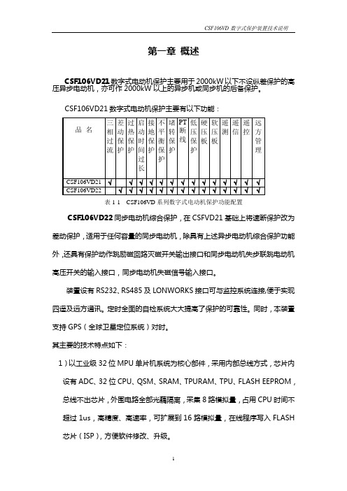
第一章概述CSF106VD21数字式电动机保护主要用于2000kW以下不设纵差保护的高压异步电动机,亦可作2000kW以上的异步机或同步机的后备保护。
表1-1 CSF106VD系列数字式电动机保护功能配置CSF106VD22同步电动机综合保护,在CSFVD21基础上将速断保护改为差动保护,适用于任何容量的同步电动机,除具有上述异步电动机综合保护功能外,还具有保护动作跳励磁回路灭磁开关输出接口和同步电动机失步联跳电动机高压开关的输入接口,同步电动机失磁信号输入接口。
装置设有RS232、RS485及LONWORKS接口可与监控系统连接,便于实现四遥及远方通讯。
定时全面的自检系统大大提高了保护的可靠性。
同时,本装置支持GPS(全球卫星定位系统)对时。
其主要的技术特点如下:1)以工业级32位MPU单片机系统为核心部件,采用内部总线方式,芯片内设有ADC、32位CPU、QSM、SRAM、TPURAM、TPU、FLASH EEPROM,总线不出芯片,外围电路全部光藕隔离,采集8路模拟量,占用CPU时间不超过1us,高精度、高速率,可扩展到16路模拟量,在线程序写入FLASH芯片(ISP),方便软件修改、升级。
2)128×64点大液晶全汉字显示,调试全部为汉字菜单结构,使用方便、直观、信息详尽丰富。
3)采用工业级芯片,表面贴工艺,体积小,抗震、抗干扰能力强、可靠性高。
4)前面板232串口带光电隔离,可在现场实现通讯,提供更加方便友好的调试操作环境。
5)结构上设计合理,全封闭机箱坚固、抗震、抗干扰能力强,机箱小巧,适合安装于保护屏、开关柜等处。
6)该保护共可录入4套保护定值,便于现场运行。
7)可扩展工业级CAN总线,LON总线网络,组网方便、经济、可靠、可与监控系统直接通讯。
8)自动记录故障数据,掉电不丢失,便于事故分析。
9)线路故障时,除提供光报信号外,保护自动弹出全中文故障报告,直观明了,便于维护。
E53NA50中文资料

E53NA50中文资料STE53NA50N -CHANNEL ENHANCEMENT MODEFAST POWER MOS TRANSISTORs TYPICAL R DS(on)=0.075?s HIGH CURRENT POWER MODULE s AVALANCHE RUGGED TECHNOLOGYsVERY LARGE SOA -LARGE PEAK POWER CAPABILITYs EASY TO MOUNTsSAME CURRENT CAPABILITY FOR THE TWO SOURCE TERMINALSs EXTREMELY LOW Rth (Junction to case)sVERY LOW INTERNAL PARASITIC INDUCTANCEsISOLATED PACKAGE UL RECOGNIZEDAPPLICATIONS s SMPS &UPS s MOTOR CONTROL s WELDING EQUIPMENT s OUTPUT STAGE FOR PWM,ULTRASONIC CIRCUITSINTERNAL SCHEMATIC DIAGRAMFebruary 1998ABSOLUTE MAXIMUM RATINGSSymbol ParameterValue Unit V DS Drain-source Voltage (V GS =0)500V V DGR Drain-gate Voltage (R GS =20k ?)500V V GS Gate-source Voltage ±30V I D Drain Current (continuous)at T c =25oC 53A ID Drain Current (continuous)at T c =100o C 33A I DM(?)Drain Current (pulsed)212A P to t Total Dissipation at T c =25oC 460W Derating Factor 3.68W/o CT st g Storage Temperature-55to 150o C T j Max.Operating Junction Temperature 150oCV ISOInsulation Withhstand Voltage (AC-RMS)2500V (?)Pulse width limited by safe operating areaTYPE V DSS R DS(on)I D STE53NA50500V<0.085?53AISOTOP1/7THERMAL DATAR t hj-ca se R thc-h Thermal Resistance Junction-case Max Thermal Resistance Case-heatsink With ConductiveGrease Applied Max0.270.05o C/Wo C/WAVALANCHE CHARACTERISTICSSymbol Parameter Max Value UnitI AR Avalanche Current,Repetitive or Not-Repetitive(pulse width limited by T j max,δ <1%)26AE AS Single Pulse Avalanche Energy(starting T j=25o C,I D=I AR,V DD=50V)1014mJELECTRICAL CHARACTERISTICS(T case=25o C unless otherwise specified)OFFSymbol Parameter Test Conditions Min.Typ.Max.Unit V(BR)DSS Drain-sourceBreakdown VoltageI D=1mA V GS=0500VI DSS Zero Gate VoltageDrain Current(V GS=0)V DS=Max RatingV DS=Max Rating T c=125o C1001000μAμAI GSS Gate-body LeakageCurrent(V DS=0)V GS=±30V±400nA ON(?)Symbol Parameter Test Conditions Min.Typ.Max.Unit V GS(th)Gate ThresholdVoltageV DS=V GS I D=1mA 2.253 3.75VR DS(on)Static Drain-source OnResistanceV GS=10V I D=27A0.0750.085?I D(o n)On State Drain Current V DS>I D(on)x R DS(on)maxV GS=10V53A DYNAMICSymbol Parameter Test Conditions Min.Typ.Max.Unit g fs(?)ForwardTransconductanceV DS>I D(on)X RDS(on)MAX I D=27A25SC iss C oss C rss Input CapacitanceOutput CapacitanceReverse TransferCapacitanceV DS=25V f=1MHz V GS=0131500450162000650nFpFpFSTE53NA50 2/7ELECTRICAL CHARACTERISTICS(continued) SWITCHING ONSymbol Parameter Test Conditions Min.Typ.Max.Unit t d(on) t r Turn-on TimeRise TimeV DD=250V I D=27AR G=4.7 ?V GS=10V(see test circuit,figure1)579280130nsnsQ g Q gs Q gd Total Gate ChargeGate-Source ChargeGate-Drain ChargeV DD=400V I D=53A V GS=10V47054219658nCnCnCSWITCHING OFFSymbol Parameter Test Conditions Min.Typ.Max.Unit t r(Vof f) t ft c Off-voltage Rise TimeFall TimeCross-over TimeV DD=400V I D=53AR G=4.7 ?V GS=10V(see test circuit,figure3)1053614514550205nsnsnsSOURCE DRAIN DIODESymbol Parameter Test Conditions Min.Typ.Max.Unit I SD I SDM(?)Source-drain CurrentSource-drain Current(pulsed)53212AAV SD(?)Forward On Voltage I SD=53A V GS=0 1.6V t rr Q rr I RRM Reverse RecoveryTimeReverse RecoveryChargeReverse RecoveryCurrentI SD=53A di/dt=100A/μsV R=100V T j=150o C(see test circuit,figure3)100031.563nsμCA(?)Pulsed:Pulse duration=300μs,duty cycle1.5% (?)Pulse width limited by safe operating areaSafe Operating Area for Thermal ImpedanceSTE53NA503/7Output Characteristics TransconductanceGate Charge vs Gate-source Voltage Transfer Characteristics Static Drain-source On Resistance Capacitance VariationsSTE53NA50 4/7Normalized Gate Threshold Voltage vs TemperatureSource-drain Diode Forward Characteristics Fig.2:Gate Charge test Circuit Normalized On Resistance vs Temperature Fig.1:Switching Times Test Circuits For Resistive Load Fig.3:Test Circuit For Inductive Load Switching And Diode Recovery TimesSTE53NA505/7DIM.mm inch MIN.TYP.MAX.MIN.TYP.MAX.A 11.812.20.4660.480B 8.99.10.3500.358C 1.95 2.050.0760.080D 0.750.850.0290.033E 12.612.80.4960.503F 25.1525.50.990 1.003G 31.531.71.240 1.248H 40.157J 4.1 4.30.1610.169K 14.915.10.5860.594L 30.130.31.185 1.193M 37.838.21.488 1.503N 40.157O7.88.20.3070.322BEHONJ K L MFACGDISOTOP MECHANICAL DATASTE53NA506/7Information furnished is believed to be accurate and reliable.However,SGS-THOMSON Microelectronics assumes no responsability for the consequences of use of such information nor for any infringement of patents or other rights of third parties which may results from its use.No license is granted by implication or otherwise under any patent or patent rights of SGS-THOMSON Microelectronics.Specifications mentioned in this publication are subject to change without notice.This publication supersedes and replaces all information previously supplied.SGS-THOMSON Microelectronics products are not authorized for use as critical components in life support devices or systems without express written approval of SGS-THOMSON Microelectonics.1998SGS-THOMSON Microelectronics -Printed in Italy -All Rights ReservedSGS-THOMSON Microelectronics GROUP OF COMPANIESAustralia -Brazil -Canada -China -France -Germany -Italy -Japan -Korea -Malaysia -Malta -Morocco -The Netherlands -Singapore -Spain -Sweden -Switzerland -Taiwan -Thailand -United Kingdom -U.S.A...STE53NA50 7/7。
ST500使用说明书

ST500智能型电动机控制器的使用说明书调试手册苏州万龙集团有限公司2006年4月目录一、控制器面板及端子布置 (3)1.1 控制器正面布置 (3)1.2 控制器侧边端子的端子号布置图及功能说明 (4)1.3控制器端子号定义 (4)二、ST522显示模块功能介绍 (7)三、普通用户菜单功能介绍 (7)四、高级用户菜单功能介绍 (10)五、参数设置参考 (11)5.1各种保护特性说明k系数设置参照表 (11)5.2 系统参数设置 (12)5.3 电动机功率范围和额定电流关系5.4 控制权限设定表六、各种运行方式典型二次接线图 (18)6.1、直接起动典型接线图6.2、保护模式下的典型接线图6.3、双向/可逆启动模式的典型接线图6.4、星三角起动模式的典型接线图七、常见故障分析及排除方法 (18)八、安全事项 (17)一、控制器面板及端子布置1.1 控制器正面布置(控制器的DI/DO端子功能可编程,其不同功能见1.3定义)万龙电器图1 控制器面板布置图序1: 开关量输入公共端(对应端子号1)。
序2: DI1开关量,按逆时针顺序 DI1~DI9 共9个可编程光隔开关量输入端。
序3:开关量输出 DO1,DO2公共端。
序4:开关量输出DO1。
序5:开关量输出DO2。
序6:开关量输出 DO3,DO4公共端。
序7:开关量输出 DO3,一般为常闭,正常工作时为常开。
序8:开关量输出 DO4。
序9:电源输入端子(对应端子号17,18)。
序10:指示灯:故障指示灯,在故障报警延时过程中闪烁,发生故障跳闸后恒亮。
总线提示灯,在远程通讯建立后恒亮,未建立时不亮。
运行指示灯,在运行状态下闪烁,在停车时恒亮。
序11:复位按键,用于清除状态指示和故障报警接点信号。
序12:通讯接口,用于连接远程通讯网络。
序13:用于连接显示模块ST522接口。
插页:为增加继电器的容量,采用增加ST202模块的方法,具体接线图如下:101817B C COM DA DO2DO1DO4DO3A DCOMC B ST202模块苏州万龙集团有限公司- 5 -1.3.2 控制器DI/DO端子的可编程功能编号说明见下表控制器光隔开关量输入端子最多同时用9个,继电器输出最多同时用4个。
电磁保护设备TeSys GV系列产品参数表说明书
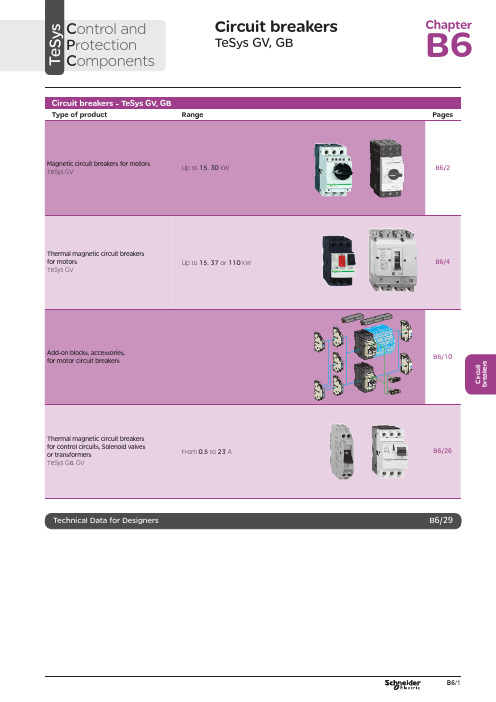
C i r c u i t b r e a k e r sCircuit breakersTeSys GV, GBC ontrol and P rotection C omponentsChapterB60.75g g 1.1g g 1.5375 2.533.5 LR2 K0308GV2LE071.1g g –––––– 2.533.5 LR2 K0308GV2LE071.5g g 1.5g g 3375451 LR2 K0310GV2LE08––– 2.2g g –––451 LR2 K0312GV2LE082.2g g 3501004375 6.378 LR2 K0312GV2LE103g g 410100 5.537510138 LR2 K0314GV2LE144g g 5.510100–––10138 LR2 K0316GV2LE14––––––7.537510138 LRD 14GV2LE14––––––937514170 LRD 16GV2LE165.515507.56751137514170 LR2 K0321GV2LE167.5155096751537518223 LRD 21GV2LE20915401147518.537525327 LRD 22GV2LE2211154015475–––25327 LRD 22GV2LE2215105018.54752237532416LRD 32GV2LE32(1) As % of Icu.g ) > 100 kA.GV2 LE10D F 526144.t i fC i r c u i t b r e a k e r s0.09––––––0.45LRD 03GV2L030.12g g –––0.37g g 0.638LRD 04GV2L040.18g g ––––––0.638LRD 04GV2L04––––––0.55g g 113LRD 05GV2L050.25g g ––––––113LRD 05GV2L05––––––0.75g g 113LRD 06GV2L050.37g g 0.37g g –––113LRD 05GV2L050.55g g 0.55g g 1.1g g 1.622.5LRD 06GV2L06–––0.75g g ––– 1.622.5LRD 06GV2L060.75g g 1.1g g 1.54100 2.533.5LRD 07GV2L07Example: GV3 L32 becomes GV3 L326.(1) As % of Icu. Associated current limiter or fuses, where required. See characteristics page B6/33.g > 100 kA.GV2 L10D F 526145.t i fGV3 L65D F 526146.t i fTeSys GVThermal-magnetic motor circuit breakers GV2 ME0.06gg––––––0.16…0.252.4GV2ME020.09g g––––––0.25…0.405GV2ME030.12 0.18g g g g – –– –– – 0.37 –g–g –0.40…0.638GV2ME040.25gg––– 0.55gg0.63…113GV2ME050.37 0.55 –g g –g g –0.37 0.55 0.75g g g g g g – 0.75 1.1– g g – g g 1…1622.5GV2ME060.75g g1.1gg1.5375 1.6...2.533.5GV2ME071.1 1.5g g g g 1.5 2.2g g g g 2.2 3 3 375 75 2.5 (4)51GV2ME082.2gg350100 43754...6.378GV2ME103 4g g g g 4 5.510 10100 100 5.5 7.5 3 375 756 (10)138GV2ME145.5 –15 –50 –7.5 – 6 –75 – 9 11 3 375 759…14170GV2ME167.5155096751537513…18223GV2ME209154011475 18.537517…23327GV2ME2111154015475 –––20…25327GV2ME22 (3)15105018.54752237524 (32)416GV2ME32Motor circuit breakers from 0.06 to 15 kW / 400 V, with lugsTo order thermal magnetic circuit breakers with connection by lugs, add the digit 6 to the end of reference selected above.Example: GV2 ME08 becomes GV2 ME086.Thermal magnetic circuit breakers GV2 ME with built-in auxiliary contact block With instantaneous auxiliary contact block (composition, see page B6/11):b GV AE1, add suffix AE1TQ to the motor circuit breaker reference selected above. Example: GV2 ME01AE1TQ .b GV AE11, add suffix AE11TQ to the motor circuit breaker reference selected above. Example: GV2 ME01AE11TQ .b GV AN11, add suffix AN11TQ to the motor circuit breaker reference selected above. Example: GV2 ME01AN11TQ .These circuit breakers with built-in contact block are sold in lots of 20 units in a single pack.(1) As % of Icu.(2) The thermal trip setting must be within the range marked on the graduated knob.(3) Maximum rating which can be mounted in enclosures GV2 MC or MP , please consult your Regional Sales Office. g > 100 kA.GV2 ME10D F 526134.t i fC i r c u i t b r e a k e r sTeSys GVTeSys protection componentsThermal-magnetic motor circuit breakers GV2 MEReferences0.06g g ––– 0.16…0.25 2.4GV2ME0230.09g g ––– 0.25…0.405GV2ME0330.120.18g g g g –––0.40…0.638GV2ME0430.250.37g g g g 0.37g g 0.63…113GV2ME0530.370.55g g g g 0.370.550.75g g g g g g 1…1.622.5GV2ME0630.75g g1.1g g 1.6…2.533.5GV2ME0731.11.5g g g g 1.52.2g g g g 2.5…451GV2ME0832.2g g 350100 4…6.378GV2ME10334g g g g 45.510101001006…10138GV2ME1435.515507.5675 9…14170GV2ME1637.515509675 13…18223GV2ME203911151540401147517…23327GV2ME2131115401547520 (25)327GV2ME223Contact blocksDescription Mounting Maximum number Type of contacts Sold in lots of Unitreference Instantaneous auxiliary contactsFront 1N/O + N/C 10GVAE113N/O + N/O 10GVAE203LH side2N/O + N/C 1GVAN113N/O + N/O1GVAN203AccessoryDescriptionApplicationSold in lots of Unitreference Cable end reducerFor connection of conductors from 1 to 1.5 mm 220LA9D99(1) For connection of conductors from 1 to 1.5 mm 2, the use of an LA9 D99 cable end reducer is recommended.(2) Maximum rating which can be mounted in enclosures GV2 MC or MP , please consult your Regional Sales Office (3) The thermal trip setting must be within the range marked on the graduated knob.g > 100 kA.GV2 ME pp 3D F 526135.t i fLA9 D99D F 533898.e p sTeSys GVReferencesTeSys protection componentsThermal-magnetic motor circuit breakersGV2 P, GV3 P and GV3 ME80GV2 P10D F 526137.t i fGV3 P65D F 526139.t i fGV3 P651D F 526140.t i fC i r c u i t b r e a k e r sTeSys GVReferences93610011181001581007.59707010010091150501001001115101010010012…20GV7RS20 2.0109113636100100111518181001001518.58810010015…25GV7RE25 2.0109117070100100111550501001001518.5101010010015…25GV7RS25 2.01018.53610018.522181810010022810025…40GV7RE40 2.01018.57010018.550100221010025…40GV7RS40 2.0102236100301810030810030…50GV7RE50 2.01522701003050100301010030 (50)GV7RS502.01537361004555181810010055810048...80GV7RE80 2.040377010045555050100100551010048...80GV7RS80 2.0404536100–1810075810060...100GV7RE100 2.0404570100–50100751010060...100GV7RS100 2.0405575353510010075903030100100901108810010090 (150)GV7RE1502.020557570701001007590505010010090110101010010090…150GV7RS150 2.02090110353510010011013216030303010010010016020088100100132…220GV7RE220 2.3509011070701001001101321605050501001001001602001010100100132…220GV7RS220 2.350(1) As % of lcu.TeSys protection componentsThermal-magnetic motor circuit breakers GV7 RGV7 RE40D F 526138.t i fGV7 RS220D F 526141.t i f0.12–0.120.180.18–0.370.40…0.6313GV2RT040.090.120.250.370.250.370.370.550.63…122GV2RT050.180.250.370.550.370.550.370.550.750.751.11…1.633GV2RT060.370.750.751.1 1.11.51.6…2.551GV2RT070.550.75 1.11.5 1.51.52.2 2.23 2.5…478GV2RT081.12.22.23344…6.3138GV2RT101.52.234445.5 5.57.56…10200GV2RT142.23 5.55.57.57.59119…14280GV2RT1647.57.5991513…18400GV2RT205.5911111118.517…23400GV2RT21(1) The thermal trip setting must be within the range marked on the graduated knob.GV2 RTD F 526142.t i fC i r c u i t b r e a k e r sblack handle, blue legend plate(1) The thermal trip setting must be within the range marked on the graduated knob.(2) Other accessories such as mounting, cabling and marking accessories are identical to those used for GV2 ME motor circuit breakers, see page B6/13.GV2 RTD F 526142.t i fD F 526340.e p sC i r c u i t b r e a k e r sTeSys GVDescription Mounting Maximum number Type of contacts Sold inlots of Unitreference Instantaneous auxiliary contactsFront (1)1N/O or N/C (2)10GVAE1N/O + N/C 10GVAE11N/O + N/O10GVAE20Side (LH)2N/O + N/C1GVAN11N/O + N/O1GVAN20Fault signalling contact + instantaneous auxiliary contact Side (3) (LH)1N/O (fault)+ N/O1GVAD1010+ N/C1GVAD1001N/C (fault)+ N/O1GVAD0110+ N/C1GVAD0101Short-circuit signalling contactSide (LH)1C/O common point1GVAM11(1 block on RH sideof circuit breaker GV2 ME)50 Hz GVAX11560 Hz GVAX116127 V60 Hz GVAX115220…240 V 50 Hz GVAX22560 Hz GVAX226380…400 V50 Hz GVAX38560 Hz GVAX386415…440 V 50 Hz GVAX415440 V60 Hz GVAX385Add-on contact blocksDescriptionMountingMaximum number Reference Visible isolation block (5)Front (1)1GV2AK00 (6)LimitersAt top(GV2 ME and GV2 P)1GV1L3Independent1LA9LB920(1) Mounting of a GV AE contact block or a GV2 AK00 visible isolation block on GV2 P and GV2 L .(2) Choice of N/C or N/O contact operation, depending on which way round the reversible block is mounted.(3) The GV AD is always mounted next to the circuit breaker.(4) To order an undervoltage trip: replace the dot (p ) in the reference with a U , example: GV AU025. To order a shunt trip: replace the dot (p ) in the reference with an S , example: GV AS025.(5) Visible isolation of the 3 poles upstream of circuit breaker GV2 P and GV2 L .Visible isolation block GV2 AK00 cannot be used with motor circuit breakers GV2 P32 and GV2 L32 (Ith max = 25 A).(6) Ie Max = 32 A.ReferencesTeSys protection componentsThermal-magnetic and magnetic motor circuit breakers GV2 with screw clamp connectionsAdd-on blocks and accessoriesCharacteristics:pages B6/89 and B6/94Dimensions, schemes:pages B6/70 to B6/82LA9LB920D B 126629.e p sC i r c u i t b r e a k e r sTeSys GVTerminal blockfor supply to one or more GV2 G busbar setsConnection from the top1GV1G09Can be fitted with current limiter GV1 L3 (GV2 ME and GV2 P)1GV2G05Cover for terminal block For mounting in modular panels10LA9E07Flexible 3-pole connection for connecting a GV2 to a contactor LC1-D09…D25 Centre distance between mounting rails: 100…120 mm10GV1G02Set of connections upstream/downstream For connecting GV2 ME to a printed circuit board 10GV2GA01“Large Spacing” adapter UL 508 type EFor GV2 P pp H7 (except 32 A)1GV2GH7Clip-in marker holders (supplied with each circuit breaker)For GV2 P , GV2 L, GV2 LE and GV2 RT (8 x 22 mm)100LA9D92ReferencesTeSys protection componentsThermal-magnetic and magnetic motor circuit breakers GV2 with screw clamp connectionsAccessoriesDimensions, schemes:pages B6/70 to B6/82D B 417942.e p sTeSys GVD B 126631.e p sD B 126630.e p sD B 126632.e p s7P B 106297_45.e p sExtended Rotary HandleAllows a circuit breaker or a starter-controller installed in back of an enclosure to be operated from the front of the enclosure.A rotary handle can be black or red/yellow, IP54 or IP65. It includes a function for locking the circuit breaker or the starter in the O (Off) or I (On) position(depending of the type of rotary handle) by means of up to 3 padlocks with a shank diameter of 4 to 8 mm. The extended shaft must be adjusted to use in different size enclosures. The IP54 rotary handle is fixed with a nut (Ø22) to make easierthe assembling. The new Laser Square tool brings the accuracy to align the circuit breaker and the rotary handle.device(padlocks not included)ReferencesTeSys protection componentsThermal-magnetic and magnetic motor circuit breakers GV2 with screw clamp connectionsC i r c u i t b r e a k e r sTeSys GVDescriptionMounting Maximum number Type of contacts Sold inlots of Unitreference Instantaneous auxiliary contactsFront1N/O or N/C (1)10GVAE1N/O + N/C 10GVAE11 (2)N/O + N/O10GVAE20 (2)Side (LH)2N/O + N/C1GVAN11 (2)N/O + N/O1GVAN20 (2)Fault signalling contact + instantaneous auxiliary contactFront 1N/O (fault)+ N/O1GVAED101 (2)N/O (fault)+ N/C1GVAED011 (2)Side (3) (LH)1N/O (fault)+ N/O1GVAD1010+ N/C1GVAD1001N/C (fault)+ N/O1GVAD0110+ N/C1GVAD0101Short-circuit signalling contact Side (LH)1C/O common point 1GVAM11(4)MountingVoltage ReferenceSide(1 block on RH side of circuit breaker)24 V 50 Hz GVA p 02560 Hz GVA p 02648 V 50 Hz GVA p 05560 Hz GVA p 05610050 Hz GVA p 107100…110 V 60 Hz GVA p 107110…115 V 50 Hz GVA p 11560 Hz GVA p 116120…127 V 50 Hz GVA p 125127 V 60 Hz GVA p 115200 V50 Hz GVA p 207200…220 V 60 Hz GVA p 207220…240 V 50 Hz GVA p 22560 Hz GVA p 226380…400 V 50 Hz GVA p 38560 Hz GVA p 386415…440 V 50 Hz GVA p 415415 V 60 Hz GVA p 416440 V 60 Hz GVA p 385480 V 60 Hz GVA p 415500 V 50 Hz GVA p 505600 V60 HzGVA p 505AccessoriesDescription Reference Sets of 3-pole 115 A busbars Pitch: 64 mm2 tap-off GV3 P pp and GV3 L pp GV3G2643 tap-off GV3 P pp and GV3 L pp GV3G364Cover “Large Spacing” UL 508 type E (Only one cover required on supply side)GV3 P ppGV3G66(1) Choice of N/C or N/O contact operation, depending on which way round the reversible block is mounted.(2) Contact blocks available in version with spring terminal connections. Add a figure 3 at the end of the references selected above. Example: GV AED101 becomes GV AED1013.(3) The GV AD pp is always mounted next to the circuit breaker.(4) To order an undervoltage trip: replace the dot (p ) in the reference with a U , example: GV AU025. To order a shunt trip: replace the dot (p ) in the reference with an S , example: GV AS025.Add-on blocks and accessoriesGV3 G66D F 537424.e p sTeSys GVD B 126637.e p sD B 126636.e p sD B 126632.e p s7P B 106297_45.e p sExtended Rotary HandleAllows a circuit breaker or a starter-controller installed in back of an enclosure to be operated from the front of the enclosure.A rotary handle can be black or red/yellow, IP54 or IP65. It includes a function for locking the circuit breaker or the starter in the O (Off) or I (On) position(depending of the type of rotary handle) by means of up to 3 padlocks with a shank diameter of 4 to 8 mm. The extended shaft must be adjusted to use in different size enclosures. The IP54 rotary handle is fixed with a nut (Ø22) to make easierthe assembling. The new Laser Square tool brings the accurency to align the circuit breaker and the rotary handle.For English 10-GVAPSEN For German 10-GVAPSDE For Spanish10-GVAPSES For Chinese 10-GVAPSCN For Portuguese 10-GVAPSPT For Russian 10-GVAPSRU For Italian10-GVAPSITD F 526342.e p sB6/21C i r c u i t b r e a k e r sTeSys GVfor locking the Start button (on open-mounted product)using up to 3 padlocks(padlocks to be ordered separately)External operator for mounting on enclosure door.Red Ø40 knob on yellow plate, padlockable in position O (with up to 3 padlocks). Door locked when knob in position I, and when knob padlocked in position O.GK3AP03(1) 1 voltage trip OR 1 fault signalling contact to be fitted inside the motor circuit breaker.Other versions24 to 690 V, 50 or 60 Hz voltage trips for circuit breakers GV3 ME80.Please consult your Regional Sales Office.ReferencesTeSys protection componentsMotor circuit breakers GV3 ME80 and GK3 EF80Add-on blocks and accessoriesCharacteristics:pages B6/89 and B6/92Dimensions:page B6/47B6/22D F 526344.e p sB6/23C i r c u i t b r e a k e r sTeSys GVThese allow remote indication of the circuit breaker contact states. They can be used for signalling, electrical locking, relaying, etc. They are available in two versions: standard and low level. They include a terminal block and the auxiliary circuits leave the circuit breaker through a hole provided for this purpose.They perform the following functions, depending on where they are located in the circuit breaker:Low levelGV7AB11Fault discrimination devicesThese make it possible to:b either differentiate a thermal fault from a magnetic fault,b or open the contactor only in the event of a thermal fault.VoltageReference a 24...48 and c 24…72 V GV7AD111 (1)z 110…240 VGV7AD112 (1)Electric tripsThese allow the circuit breaker to be tripped via an electrical control signal.b Undervoltage trip GV7 AUv Trips the circuit breaker when the control voltage drops below the tripping threshold, which is between 0.35 and 0.7 times the rated voltage.v Circuit breaker closing is only possible if the voltage exceeds 0.85 times the rated voltage. Circuit breaker tripping by a GV7 AU trip meets the requirements of IEC 60947-2.b Shunt trip GV7 ASTrips the circuit breaker when the control voltage rises above 0.7 times the rated voltage.b Operation (GV7 AU or GV7 AS)v When the circuit breaker has been tripped by a GV7 AU or AS, it must be reset either locally or by remote control. (For remote control, please consult your Regional Sales Office).v Tripping has priority over manual closing: if a tripping instruction is present, manual action does not result in closing, even temporarily, of the contacts.v Durability: 50 % of the mechanical durability of the circuit breaker.TypeVoltageReference Undervoltage trip48 V, 50/60 HzGV7AU055 (1)110…130 V, 50/60 Hz GV7AU107 (1)200…240 V, 50/60 Hz GV7AU207 (1)380…440 V, 50/60 Hz GV7AU387 (1)525 V, 50 HzGV7AU525 (1)Shunt trip48 V, 50/60 HzGV7AS055 (1)110…130 V, 50/60 Hz GV7AS107 (1)200…240 V, 50/60 Hz GV7AS207 (1)380…440 V, 50/60 Hz GV7AS387 (1)525 V, 50 HzGV7AS525 (1)(1) For mounting of a GV7 AD or a GV7 AU or AS.ReferencesTeSys protection componentsThermal-magnetic motor circuit breakers GV7 R with screw clamp connectionsAdd-on blocks and accessoriesCharacteristics:pages B6/51, B6/52 and B6/56Dimensions:pages B6/79 to B6/81Schemes:page B6/83B6/24B6/25C i r c u i t b r e a k e r sTeSys GVDescription ApplicationFor use on contactors Sold in lots of Unitreference Clip-on connectors for GV7 RUp to 150 A, 1.5…95 mm 2–3GV7AC021Up to 220 A, 1.5…185 mm 2–3GV7AC022Spreader 3-pole (1)To increase the pitch to 45 mm–1GV7AC03Terminal shields IP 405 (1)Supplied with sealing accessory–1GV7AC01Phase barriersSafety accessories used when fitting of shields is impossible –2GV7AC04Insulating screens Ensure insulation between the connections and the backplate –2GV7AC05Kits for combination with contactor (2)Allowing link between thecircuit breaker and the contactor. The cover provides protection against direct finger contactLC1 F115…F1851GV7AC06LC1 F225 and F2651GV7AC07LC1 D115 and D1501GV7AC08Replaces the circuit breaker front cover; secured by screws. It includes a device for locking the circuit breaker in the O (Off) position by means of up to 3 padlocks with a shank diameter of 5 to 8 mm (padlocks not included). A conversion accessory allows the direct rotary handle to be mounted on the enclosure door. In this case, the door cannot be opened if the circuit breaker is in the “ON” position. Circuit breaker closing is inhibited if the enclosure door is open.Description TypeDegree of protection Reference Direct rotary handleBlack handle, black legend plate IP 40GV7AP03Red handle, yellow legend plateIP 40GV7AP04Adapter plate (3)Four mounting direct rotary handle on enclosure doorIP 43GV7AP05Allows a circuit breaker installed in the back of an enclosure to be operated from the front of the enclosure. It comprises:b a unit which screws onto the front cover of the circuit breaker,b an assembly (handle and front plate) to be fitted on the enclosure door,b an extension shaft which must be adjusted (distance between the mounting surface and the door: 185 mm minimum, 600 mm maximum). It includes a device for locking the circuit breaker in the O (Off) position by means of up to 3 padlocks with a shank diameter of 5 to 8 mm (padlocks not included). This prevents the enclosure door from being opened.DescriptionTypeDegree of protection Reference Extended rotary handleBlack handle, black legend plate IP 55GV7AP01Red handle, yellow legend plateIP 55GV7AP02Allows circuit breakers not fitted with a rotary handle to be locked in the O (Off) position by means of up to 3 padlocks with a shank diameter of 5 to 8 mm (padlocks not included).Description ApplicationReference Locking deviceFor circuit breaker not fitted with a rotary handleGV7V01(1) Terminal shields cannot be used together with spreaders.(2) The kit comprises links, a protective shield and a depth adjustable metal bracket for the breaker.(3) This conversion accessory makes it impossible to open the door if the device is closed and prevents the device from being closed if the door is open.ReferencesTeSys protection componentsThermal-magnetic motor circuit breakers GV7 R with screw clamp connectionsAccessoriesGV7 AC07D F 537429.e p sGV7 AC08D F 537428.e p sDimensions:pages B6/79 to B6/81B6/260.5 6.63GB2DB051143GB2DB062263GB2DB073403GB2DB084503GB2DB095663GB2DB106833GB2DB1281083GB2DB14101383GB2DB16121653GB2DB20162203GB2DB21202703GB2DB22(1) Conforming to IEC 60947-1.GB2 CBppD F 526243.t i fGB2 CD ppD F 526244.t i fGB2 DBppD F 526245.t i fPresentation, selection :page B6/84Characteristics :pages B6/85 to B6/87Dimensions :page B6/88Schemes :page B6/88B6/27C i r c u i t b r e a k e r s(1) Conforming to IEC 60947-1.Accessories for circuit breakers GB2-CB, DB and CSDescriptionSold in lots of Unitreference Busbar set for supply to 10 GB2 DB or20 GB2 CB or GB2 CS with 2 connectors1GB2G210Supply connector 10GB2G01GB2 CS ppD F 526246.t i fPresentation, selection :page B6/84Characteristics :pages B6/85 to B6/87Dimensions :page B6/88Schemes :page B6/88B6/28B6/29B6/30TeSys GVCharacteristicsTeSys protection componentsMagnetic motor circuit breakers GV2 LE and GV2 LReferences:pages B6/2 and B6/3Dimensions:pages B6/43 to B6/47Schemes:page B6/48add-on contact blocks. Side by side mounting is possible up to 40 °C.(2) When mounting on a vertical rail, fit a stop to prevent any slippage.(1) As % of Icu.Average operating times at 20 °C related to multiples of the setting currentD F 534092.e p s1 3 poles from cold state2 2 poles from cold state3 3 poles from hot stateDynamic stressI peak = f (prospective Isc) at 1.05 Ue = 435 VD F 534093.e p s1 Maximum peak current2 32 A3 25 A4 18 A5 14 A6 10 A7 6.3 A8 4 A9 2.5 A 10 1.6 A11 Limit of rated ultimate breaking capacity on short-circuit of GV2 LE (14, 18, 23 and 25 A ratings).Dynamic stressI peak = f (prospective Isc) at 1.05 Ue = 435 VD F 534094.e p s1 Maximum peak current2 32 A3 25 A4 18 A5 14 A6 10 A7 6.3 A8 4 A9 2.5 A 10 1.6 A11 Limit of rated ultimate breaking capacity on short-circuit of GV2 LE (14, 18, 23 and 25 A ratings).Thermal limit in kA 2s in the magnetic operating zone Sum of I 2dt = f (prospective Isc) at 1.05 Ue = 435 V22Prospective Isc (kA)D F 534095.e p s1 32 A 2 25 A3 18 A4 14 A5 10 A6 6.3 A7 4 A8 2.5 A9 1.6 AThermal limit in kA 2s in the magnetic operating zone Sum of I 2dt = f (prospective Isc) at 1.05 Ue = 435 V22D F 534096.e p s1 25 A and 32 A 2 18 A3 14 A 4 10 A5 6.3 A6 4 A7 2.5 A8 1.6 AThermal limit in kA 2s in the magnetic operating zone Sum of I 2dt = f (prospective Isc) at 1.05 Ue = 435 V22D F 534097.e p s1 32 A (GV2 LE32)2 25 A and 32 A (GV2 L32)3 18 A4 14 A5 10 A6 6.3 A7 4 A8 2.5 A9 1.6 A10 Limit of rated ultimate breaking capacity on short-circuit of GV2 LE (14, 18, 23 and 25 A ratings).Average operating time at 20 °C without prior current flowx the setting current (Ir)D F 534098.e p s1 3 poles from cold state2 2 poles from cold state3 3 poles from hot stateA Thermal overload relay protection zoneB GV3 L protection zoneDynamic stressI peak = f (prospective Isc) at 1.05 Ue = 435 VProspective Isc (kA)D B 418280.e p s1 Maximum peak current2 GV3 L653 GV3 L504 GV3 L405 GV3 L326 GV3 L25Thermal limit in A 2sSum of I 2dt = f (prospective Isc) at 1.05 Ue = 435 V2Prospective Isc (kA)D B 418279.e p s1 GV3 L652 GV3 L503 GV3 L404 GV3 L325 GV3 L25TeSys GVDimensions, mountingD F 537440.e p sD F 537441.e p sD F 537444.e p sTeSys protection componentsMagnetic motor circuit breakers GV2 L and GV2 LETeSys GVDimensions, mounting TeSys protection componentsMagnetic motor circuit breakers GV2 L and GV2 LED B 127415.e p sD B 127414.e p sa b Mini Maxi Mini Maxi GV2 APN pp140250GV2 APN pp + GV APH02151250GV2 APN pp + GV APK11250434--GV2 APN pp + GV APH02 + GV APK11--250445TeSys GVDimensions,mounting Sets of busbars GV2 G445, GV2 G454, GV2 G472, with terminal block GV2 G05D F 537451.e p sGV2 G445224269314359GV2 G454260314368422GV2 G472332404476548D F 537452.e p sD F 537454.e p sGV2 G345 (3 x 45 mm)134GV2 G354 (3 x 54 mm)152TeSys protection componentsMagnetic motor circuit breakers GV2 L and GV2 LED F 537480.e psD F 537435.e p sD F 510637.e p sD F 510638.e p sD B 127416.e p sD B 127417.e p sa b Mini Maxi Mini Maxi GV3 APN pp189300--GV3 APN pp + GV APK12300481GV3 APN pp + GV APH03--200300GV3 APN pp + GV APH03 + GV APK12--300492TeSys GVSchemesTeSys protection componentsMagnetic motor circuit breakers GV2 L, GV2 LE, GV3 LD F 537474.e p sD F 537475.e p sD F 537476.e p sGV2 ME, GV2 P , GV3 ME, GV3 P and GV7 R motor circuit breakers are 3-pole thermal-magnetic circuit breakers specifically designed for the control and protection of motors , conforming to standards IEC 60947-2 and IEC 60947-4-1.Connection GV2GV2 ME and GV2 P circuit breakers are designed for connection by screw clamp terminals.Circuit breaker GV2 ME can be supplied with lugs or spring terminal connections.Spring terminal connections ensure secure, permanent and durable clamping that is resistant to harsh environments, vibration and impact and are even more effective when conductors without cable ends are used. Each connection can take two independent conductors.GV3GV3 circuit breakers feature connection by BTR screws (hexagon socket head), tightened using a n° 4 Allen key.This type of connection uses the Ever Link ® system with creep compensation (1) (Schneider Electric patent).This technique makes it possible to achieve accurate and durable tightening torque, in order to avoid cable creep.GV3 circuit breakers are also available with connection by lugs. This type of connection meets the requirements of certain Asian markets and is suitable for applications subject to strong vibration, such as railway transport.GV7GV7 circuit breakers: with connection by screw clamp terminals (for bars and lugs) and by clip-on connectors.OperationControl is manual and local when the motor circuit breaker is used on its own.Control is automatic and remote when it is associated with a contactor.GV2 ME and GV3 ME80Pushbutton control.Energisation is controlled manually by operating the Start button “I” 1.De-energisation is controlled manually by operating the Stop button “O” 2, or automatically by the thermal-magnetic protection elements or by a voltage trip attachment.GV2 P , GV3 P and GV7 Rb Control by rotary knob: for GV2 P and GV3 P b Control by rocker lever: for GV7 R.Energisation is controlled manually by moving the knob or rocker lever to position “I” 1.De-energisation is controlled manually by moving the knob or rocker lever to position “O” 2.De-energisation due to a fault automatically places the knob or rocker lever in the “Trip” position 3.Re-energisation is possible only after having returned the knob or rocker lever to position “O”.(1) Creep: normal crushing phenomenon of copper conductors, that is accentuated over time.GV2 MEwith screw clamp terminals124D F 526134.t i fGV2 MEwith spring terminals connections124D F 526135.t i fGV3 P1324D F 526136.t ifGV2 P1342D F 526137.t i fGV7 R132D F 526138.t i f。
深圳市四方电气 VS500系列通用型变频器说明书

VS500系列产品继承了E系列变频器经典控制算法平台,坚持一贯严谨的设计风格,积奠了数代产品改进和优化的成果。
以其优越的性价比和强大的普适性,广泛应用于电力、纺织、造纸、冶金、食品、化工、交通、传输、电线电缆等各种传动调速领域,具有良好的可靠性和稳定性。
产品简介典型行业应用¤ ¤ 纺织¤ 传输风机水泵¤ 包装机械¤ 矿山机械¤ 食品¤ 化工¤ 陶瓷加工¤ 建材¤¤独特自适应控制技术,自动限流和限压及运行中欠 压抑制。
¤标配RS485通讯接口,可选MODBUS协议,四方 自定义协议,具备联动同步控制功能,轻松实现变 频器与PLC、工控机等其他工控设备的互联互通。
¤负荷自均衡功能,在采用RS485通讯联动控制功能 时,由主机向各从机同步发出频率和力矩负荷指令, 以达到各变频驱动系统的力矩平衡。
双行LED面板显示,便于客户同时进行监控和调试产品分析产品概况¤¤自动限流和限压及运行中欠压抑制;¤具备联动同步控制功能;¤负荷自均衡功能;独特自适应控制技术;¤¤可靠的变频器短路保护电路;¤可靠的辅助开关电源过载保护电路;¤严格的国标安规设计;自主开发的驱动保护电路专利;◆结构特点¤¤独立风道设计;人体工程学操作面板;产品架构选配键盘VS500-4T0075/VS500-2T0037及以下标配选配VS500-4T0075/VS500-2T0037以上标配双行LED电位器面板 DPNL320EB双行LED按键面板DPNL320EA单LED电位器面板DPNL320ECS单LED按键面板DPNL320EDS注:上图为VS500-4T0075机型分解图,由于产品大小不同,内部结构会有所变更,请以实物为准可拆卸直流风扇,易于清理模块式组装方式系统接线图技术规格0 Hz ~400Hz电阻负载外部脉冲V/F曲线(电压频率特性)电压最大输出频率的 0.1%以内设定输出频率的0.01%以内最大输出频率的0.2%以内最大频率的 0.1%手动设定:额定输出的0.0~20.0%;自动提升:根据输出电流自动确定提升转矩0.01Hz 最大输出频率的 0.1%基准频率在5 ~400Hz任意设定,多节点V/F曲线任意设定、可选择恒转矩、低减转矩1、低减转矩2、三种固定曲线VVVF空间电压矢量2T#系列: 0~220 V 110% 长期; 150% 1分钟; 180% 2秒输入额定电压、频率电压允许变动范围三相(4T#系列)380V 50/60Hz 三相(4T#系列)300V~460V 三相(2T#系列)220V 50/60Hz 三相(2T#系列)170V~270V 4T#系列: 0~380 V输出频率过载能力控制方式控制特性频率设定分辨率模拟输入模拟端子输入数字设定外部脉冲频率精度数字输入转矩提升自动限流与限压无论在加速、减速或稳态运行过程中,皆自动侦测电机定子电流和电压,依据独特算法将其抑制在允许的范围内运行中欠压抑制特别针对低电网电压和电网电压频繁波动的用户,即使在低于允许的电压范围内,系统亦可依据独特之算法和残能分配策略,维持最长可能的运行时间控制特性多段速与摆频运行8段可编程多段速控制、6种运行模式可选、15段端子选择多段速控制。
- 1、下载文档前请自行甄别文档内容的完整性,平台不提供额外的编辑、内容补充、找答案等附加服务。
- 2、"仅部分预览"的文档,不可在线预览部分如存在完整性等问题,可反馈申请退款(可完整预览的文档不适用该条件!)。
- 3、如文档侵犯您的权益,请联系客服反馈,我们会尽快为您处理(人工客服工作时间:9:00-18:30)。
®Mono and Colour Digital Video CMOS Image SensorsVV5404 & VV6404DESCRIPTIONVV5404 and VV6404 are highly integrated CMOS VLSI sensors which enables high standards of performance and image quality at a very cost-effective price point. The 356 x 292 monochrome device offers one of the simplest routes currently available to design-in of imaging applications, while the colour device is ideal for low cost PC camera applications.Both devices incorporate a comprehensive range of on-board controls eliminating the need for additional support chips. On-chip A/D conversion provides 8 bit digital output and the device set up is fully automatic via the built-in automatic black level calibration algorithm.Exposure and gain settings are programmable and operation is controlled via a serial interface.This sensors offer variable frame rates of up to 30 frames per second and a 4 wire digital video bus. The digital interface also provides a tri-stateable data qualification clock and frame synchronisation signal.Hand-held products, in applications such as PDAs, bar code scanning or automatic meter reading, will benefit from the low power requirements and from the inbuilt sleep and power down modes.The price and performance standards introduced with the VV5404 and VV6404 enable use of an imaging solution where previously it may not have been practicable on cost grounds.BLOCK DIAGRAMFEATURES•CIF Format mono or colour pixel array •Up to 30 frames per second operation •On-chip 8 bit analogue to digital converter •Low power consumption •Up to 356 x 292 pixel image size •Automatic exposure and gain control •Serial interface control•Programmable exposure and gain values •Automatic black level calibration •4-wire digital video bus •Evaluation kit availableAPPLICATIONS•PC Cameras •Biometrics •Inspection SystemsSPECIFICATIONSImportant:1.A colour co-processor is required to convert the VV6404 sensor’s video data stream of raw colourised pixel data into either a CIF or QCIF for-mat RGB or YUV colour image.2.VV5404 and VV6404 do NOT have any form of automatic exposure control. This must be performed externally.SAMPLE & HOLDHORIZONTAL SHIFTPHOTO DIODEANALOG VOLTAGE REFS.SDA SCLD[3:0]VERTICAL SHIFT REGISTERCLKO 8-bit ADCARRAYREGISTERSERIAL INTER-FACEOUTPUT FORMATGAINIMAGE FORMATBLACK CALIBRATIONEXPOSURE REGISTERSSTAGEOEBFST QCK SINCLKI Pixel resolution 356 x 292 (CIF)Array size 4.272mm x 3.212mm Pixel size 12.0 µm x 11.0 µm Min. illumination 0.1 luxExposure control Automatic (to 25000:1)Gain control Automatic (to +20dB)Signal/Noise ratio46dBSupply voltage5.0v DC +/− 5%Supply current <75mA Operating temperature (ambient)0o C - 40o C(for extended temp. info please con-tact STMicroelectronics)Package type48LCCTable of Contents1. Introduction. . . . . . . . . . . . . . . . . . . . . . . . . . . . . . . . . . . . . . . . . . . . . . . . . . . . . . . . . . .42. Operating Modes . . . . . . . . . . . . . . . . . . . . . . . . . . . . . . . . . . . . . . . . . . . . . . . . . . . . . .6 2.1 Image Read-out Options. . . . . . . . . . . . . . . . . . . . . . . . . . . . . . . . . . . . . . . . . . . . . . . . .62.2 Frame Rate Options. . . . . . . . . . . . . . . . . . . . . . . . . . . . . . . . . . . . . . . . . . . . . . . . . . . .63. Exposure Control . . . . . . . . . . . . . . . . . . . . . . . . . . . . . . . . . . . . . . . . . . . . . . . . . . . . . .84. Digital Video Interface Format. . . . . . . . . . . . . . . . . . . . . . . . . . . . . . . . . . . . . . . . . . . .9 4.1 General description. . . . . . . . . . . . . . . . . . . . . . . . . . . . . . . . . . . . . . . . . . . . . . . . . . . . .9 4.2 Embedded control data. . . . . . . . . . . . . . . . . . . . . . . . . . . . . . . . . . . . . . . . . . . . . . . . . .9 4.2.1 The combined escape and sync character . . . . . . . . . . . . . . . . . . . . . . . . . . . . . . . . .9 4.2.2 The command word. . . . . . . . . . . . . . . . . . . . . . . . . . . . . . . . . . . . . . . . . . . . . . . . . . .9 4.2.3 Supplementary Data. . . . . . . . . . . . . . . . . . . . . . . . . . . . . . . . . . . . . . . . . . . . . . . . .13 4.3 Video timing reference and status/configuration data. . . . . . . . . . . . . . . . . . . . . . . . . .13 4.3.1 Blank lines. . . . . . . . . . . . . . . . . . . . . . . . . . . . . . . . . . . . . . . . . . . . . . . . . . . . . . . . .14 4.3.2 Black line timing. . . . . . . . . . . . . . . . . . . . . . . . . . . . . . . . . . . . . . . . . . . . . . . . . . . . .14 4.3.3 Valid video line timing . . . . . . . . . . . . . . . . . . . . . . . . . . . . . . . . . . . . . . . . . . . . . . . .14 4.3.4 Start of frame line timing . . . . . . . . . . . . . . . . . . . . . . . . . . . . . . . . . . . . . . . . . . . . . .14 4.3.5 End of frame line timing. . . . . . . . . . . . . . . . . . . . . . . . . . . . . . . . . . . . . . . . . . . . . . .14 4.4 Detection of sensor using data bus state . . . . . . . . . . . . . . . . . . . . . . . . . . . . . . . . . . .14 4.5 Resetting the Sensor Via the Serial Interface. . . . . . . . . . . . . . . . . . . . . . . . . . . . . . . .14 4.6 Power-up, Low-power and Sleep modes . . . . . . . . . . . . . . . . . . . . . . . . . . . . . . . . . . .14 4.6.1 Power-Up/Down (Figure 12) . . . . . . . . . . . . . . . . . . . . . . . . . . . . . . . . . . . . . . . . . . .18 4.6.2 Low-Power Mode (Figure 10) . . . . . . . . . . . . . . . . . . . . . . . . . . . . . . . . . . . . . . . . . .18 4.6.3 Sleep Mode (Figure 11). . . . . . . . . . . . . . . . . . . . . . . . . . . . . . . . . . . . . . . . . . . . . . .18 4.6.4 Application of the system clock during sensor low-power modes . . . . . . . . . . . . . . .22 4.7 Qualification of Output Data . . . . . . . . . . . . . . . . . . . . . . . . . . . . . . . . . . . . . . . . . . . . .22 4.7.1 Using the External Clock signal applied to CKI. . . . . . . . . . . . . . . . . . . . . . . . . . . . .22 4.7.2 Data Qualification Clock, QCK. . . . . . . . . . . . . . . . . . . . . . . . . . . . . . . . . . . . . . . . . .224.7.3 Frame Start Signal, FST . . . . . . . . . . . . . . . . . . . . . . . . . . . . . . . . . . . . . . . . . . . . . .225. Serial Control Bus . . . . . . . . . . . . . . . . . . . . . . . . . . . . . . . . . . . . . . . . . . . . . . . . . . . .27 5.1 General Description . . . . . . . . . . . . . . . . . . . . . . . . . . . . . . . . . . . . . . . . . . . . . . . . . . .27 5.2 Serial Communication Protocol . . . . . . . . . . . . . . . . . . . . . . . . . . . . . . . . . . . . . . . . . .27 5.3 Data Format. . . . . . . . . . . . . . . . . . . . . . . . . . . . . . . . . . . . . . . . . . . . . . . . . . . . . . . . .27 5.4 Message Interpretation. . . . . . . . . . . . . . . . . . . . . . . . . . . . . . . . . . . . . . . . . . . . . . . . .28 5.5 The Programmers Model . . . . . . . . . . . . . . . . . . . . . . . . . . . . . . . . . . . . . . . . . . . . . . .29 5.5.1 DeviceH [000_00002] and DeviceL [000_ 00012]. . . . . . . . . . . . . . . . . . . . . . . . . . .31 5.5.2 Status0 [000_00102] . . . . . . . . . . . . . . . . . . . . . . . . . . . . . . . . . . . . . . . . . . . . . . . . .31 5.5.3 Line_count_H [000_00112] & Line_count_L [000_01002]. . . . . . . . . . . . . . . . . . . . .31 5.5.4 Setup0 [001_00002] . . . . . . . . . . . . . . . . . . . . . . . . . . . . . . . . . . . . . . . . . . . . . . . . .32 5.5.5 Setup1 [001_00012] . . . . . . . . . . . . . . . . . . . . . . . . . . . . . . . . . . . . . . . . . . . . . . . . .32 5.5.6 Setup2 [001_00102] . . . . . . . . . . . . . . . . . . . . . . . . . . . . . . . . . . . . . . . . . . . . . . . . .33 5.5.7 Setup4 [001_01002] . . . . . . . . . . . . . . . . . . . . . . . . . . . . . . . . . . . . . . . . . . . . . . . . .33 5.5.8 Setup5 [001_01012] . . . . . . . . . . . . . . . . . . . . . . . . . . . . . . . . . . . . . . . . . . . . . . . . .34 5.5.9 Exposure Control Registers [010_00002] - [010_10012]. . . . . . . . . . . . . . . . . . . . . .35 5.5.10 ADC Setup Register AS0 [111_01112] . . . . . . . . . . . . . . . . . . . . . . . . . . . . . . . . . .37 5.6 Types of messages. . . . . . . . . . . . . . . . . . . . . . . . . . . . . . . . . . . . . . . . . . . . . . . . . . . .38 5.6.1 Single location, single data write. . . . . . . . . . . . . . . . . . . . . . . . . . . . . . . . . . . . . . . .385.6.2 Single location, single data read.. . . . . . . . . . . . . . . . . . . . . . . . . . . . . . . . . . . . . . . .38 5.6.3 No data write followed by same location read. . . . . . . . . . . . . . . . . . . . . . . . . . . . . .38 5.6.4 Same location multiple data write.. . . . . . . . . . . . . . . . . . . . . . . . . . . . . . . . . . . . . . .39 5.6.5 Same location multiple data read . . . . . . . . . . . . . . . . . . . . . . . . . . . . . . . . . . . . . . .39 5.6.6 Multiple location write . . . . . . . . . . . . . . . . . . . . . . . . . . . . . . . . . . . . . . . . . . . . . . . .40 5.6.7 Multiple location read. . . . . . . . . . . . . . . . . . . . . . . . . . . . . . . . . . . . . . . . . . . . . . . . .405.7 Serial Interface Timing . . . . . . . . . . . . . . . . . . . . . . . . . . . . . . . . . . . . . . . . . . . . . . . . .416. Clock Signal . . . . . . . . . . . . . . . . . . . . . . . . . . . . . . . . . . . . . . . . . . . . . . . . . . . . . . . . .426.8 Synchronising 2 or More Cameras. . . . . . . . . . . . . . . . . . . . . . . . . . . . . . . . . . . . . . . .437. Detailed specifications. . . . . . . . . . . . . . . . . . . . . . . . . . . . . . . . . . . . . . . . . . . . . . . . .45 7.1 General. . . . . . . . . . . . . . . . . . . . . . . . . . . . . . . . . . . . . . . . . . . . . . . . . . . . . . . . . . . . .457.2 DC characteristics. . . . . . . . . . . . . . . . . . . . . . . . . . . . . . . . . . . . . . . . . . . . . . . . . . . . .458. Physical. . . . . . . . . . . . . . . . . . . . . . . . . . . . . . . . . . . . . . . . . . . . . . . . . . . . . . . . . . . . .46 8.1 Pinout Diagram. . . . . . . . . . . . . . . . . . . . . . . . . . . . . . . . . . . . . . . . . . . . . . . . . . . . . . .46 8.2 Signal Names. . . . . . . . . . . . . . . . . . . . . . . . . . . . . . . . . . . . . . . . . . . . . . . . . . . . . . . .47 8.3 48LCC Mechanical Dimensions . . . . . . . . . . . . . . . . . . . . . . . . . . . . . . . . . . . . . . . . . .49 8.4 VV6404 Sensor Support Circuit Schematic Diagram. . . . . . . . . . . . . . . . . . . . . . . . . .508.5 Sensor Support Circuit Component List . . . . . . . . . . . . . . . . . . . . . . . . . . . . . . . . . . .509. Ordering Information . . . . . . . . . . . . . . . . . . . . . . . . . . . . . . . . . . . . . . . . . . . . . . . . . .521.IntroductionVV5404 and VV6404 are CIF format CMOS image sensors capable of outputing digital pixel data at frame rates, of upto 30 frames per second. The VV5404 is a monochrome part, while the VV6404 has a colour filter applied over the sensor array.Important: The VV6404 sensor’s video data stream only contains raw colourised pixel data. A colour co-processor is required to generate for example either a CIF or a QCIF format YUV colour image.The 356 x 292 pixel sensors have an on-chip 8-bit analogue to digital converter (Figure 1). The sensors offer very flexible digital interface, the main components of which are listed below:1. A tri-stateable 4-wire data bus (D[3:0]) for sending both video data and embedded timing references.2. A data qualification clock, QCK, which can be programmable via the serial interface to behave in a number of different ways (T ri-stateable).3. A frame start signal, FST (T ri-stateable).4. A 2-wire serial interface (SDA,SCL) for controlling and setting up the device.5.The ability to synchronise the operation of multiple cameras - synchronisation input, SIN.An 8-bit pixel value is transmitted across the 4 wire tri-stateable databus as series pair of 4-bit nibbles, most significant nibble first. Along within the pixel data, codes representing the start and end frames and the start and end of lines are embedded within the video data stream to allow the video processor to synchronise with video data the camera module is generating. Section 4. defines the format for the output video datastream.To complement the embedded control sequences a data qualification clock, QCK, and a frame start signal are also available. QCK can be set-up to either be:1.Disabled2.Free-running.3.Qualify only the control sequences and the pixel data.4.Qualify the pixel data onlyThere is also the choice of two different QCK frequencies, where one is twice the frequency of the other.SAMPLE & HOLDHORIZONTAL SHIFTPHOTO DIODEANALOG VOLTAGE REFS.SDA SCLD[3:0]VERTICAL SHIFT REGISTERCLKO 8-bit ADCARRAYREGISTERSERIAL INTER-FACEFigure 1 : Block Diagram of VV5404 and VV6404 Image SensorsOUTPUT FORMATGAINIMAGE FORMATBLACK CALIBRATIONEXPOSURE REGISTERSSTAGEOEBFST QCK SINCLKIVV5404 & VV64041.Fast QCK: the falling edge of the clock qualifies the nibble data irrespective of whether it is the most or the least significant nibble.2.Slow QCK: the rising edge of the clock qualifies the most significant nibbles while the falling edge of the clock qualifies the least significant nibbles.The FST can be enabled/disabled via the serial interface.OEB tri-states all 4 databus lines, D[3:0], the qualification clock, QCK and the frame start signal, FST.There are 3 main ways of interfacing to the VV5404 or VV6404 sensor based on the above signals:1.The processor capturing the data (or colour co-processor for VV6404) supplies the sensor clock, CKI, and uses the embedded control sequences to synchronise with the frame and line level timings. Thus the processor and sensor are running off derivatives of the same fundamental clock (4 fsc - 14.31818 MHz). T o allow the receiver to determine the best sampling position of the video data, during its power-up sequence the sensor outputs a 101010... sequence on each of its databus lines for the video processor to lock on to.2.The video processor uses a free-running QCK supplied by the sensor to sample the incoming video datastream. The embedded control sequences are used to synchronise the frame and line level timings. A crystal is used to generate the clock for the sensor.3.The video processor uses FST and the data only mode for QCK to synchronise to the incoming video data. Pri-marily intended for interfacing to frame grabbers.The 2-wire serial interface provides complete control over how the sensor is setup and run. Exposure and gain values are programmed via this interface. Section 5. defines the communications protocol and the register map of all the locations which can be accessed via the serial interface.Using the first two interface options outlined above it is possible to control the sensor and receive video data via a 9-wire cable between the sensor and the video processor/colour-processor.1. A 4-wire data bus (D[3:0]) for sending both video data and embedded timing references.2. A 2-wire serial interface (SDA,SCL).3.The clock for the sensor or QCK from the sensor.4.VCC and GND power lines.The various image read-out and frame rate options are detailed in Sections 2 and 3 respectively.Figure 2 : Interfacing OptionsSDA SCL D[3:0]CLKI SensorColour Co-processor (processor)SDA SCLD[3:0]QCK SensorColour Co-processor (processor)FSTVV5404 & VV64042.Operating Modes2.1Image Read-out OptionsThe output image format is CIF (352 x 288 pixel array). To provide the colour co-processor with the extra information it needs for interpolation at the edges of the VV6404 pixel array, an optional border 2 pixels deep on all 4 sides of the array can be enabled (Figure 4). The resulting image size of 356 x 292 pixels is the default power up state for this camera module. The border option is programmable via the serial interface.Image read-out is either non-interlaced raster scan, or ‘shuffled’ non-interlaced raster scan.The shuffled raster scan order differs from a conventional raster in that the pixels of individual rows are re-ordered, with the odd pixels within a row read-out first, followed by the even pixels.This ‘shuffled’ read-out within a line, is useful in the VV6404 device as it groups pixels of the same colour (according to the Bayer pattern - Figure 3) together, reducing cross talk between the colour channels.NOTE: This option is on by default in both VV5404 and VV6404 sensors and is controllable via the serial interface.2.2Frame Rate OptionsTwo options: 30 fps or 25 fps (Assuming a 7.15909 MHz input clock and the default clock divider setting). The number of video lines in for each frame rate is the same (304), the slower frame rate is implemented by extending the line period from 393 pixel periods to 471 pixel periods. 30 fps is the default option, the frame rate is programmable via the serial interface.BorderImage size (column x row)Disabled 352 x 288Enabled356 x 292DefaultTable 1 : Image Format Selection.Frame Rate (fps)Frame Timing (Pixels x Lines)25471 x 30430393 x 304defaultTable 2 : Frame Rate SelectionBlueGreenGreen Red Even Columns (0, 2, 4,...)Odd Columns (1, 3, 5,...)Even Rows (0, 2, 4,...)Odd Rows (1, 3, 5,...)Figure 3 : Bayer Colourisation Pattern. (VV6404 only)CD5404-6404F-A 7/54Blue GreenGreen RedBlue GreenGreen RedBlue GreenGreen RedBlue GreenGreen RedBlue GreenGreen RedBlue GreenGreen RedBlue GreenGreen RedBlue GreenGreen Red355354353352289291290288132321Figure 4 : VV6404 Colourised Image Format352 Pixels288Pixels292Pixels356 Pixels0, 1, 2, 3,...... 352, 353, 354, 3550, 1, 2, 3,...... 288, 289, 290, 291Border Rows and Columns Pixel ArrayVV5404 & VV64043.Exposure ControlThe exposure time for a pixel and the gain of the input amplifier to the 8-bit ADC are programmable via the serial interface. The explanation below assumes that the gain and exposure values are updated together as part of a 5 byte serial interface auto-increment sequence.The exposure is divided into 2 components - coarse and fine. The coarse exposure value sets the number of lines a pixel exposes for, while the fine exposure sets the number of additional pixel clock cycles a pixel integrates for. The sum of the two gives the overall exposure time for the pixel array.30 fps mode: Exposure Time = (Clock Divisor) x (Coarse x 393 + Fine) x (CKI clock period)/25 fps mode: Exposure Time = (Clock Divisor) x (Coarse x 471 + Fine) x (CKI clock period)30 fps mode25 fps modeValue UnitsMin.Max.Min.Max.Coarse Video Lines03020302Fine Pixel Clocks03560434Table 3 : Coarse and Fine Exposure Ranges.If an exposure value is loaded outwith the valid ranges listed in the above table the value is clipped to lie within the above ranges.Gain Code, G[2:0]Amplifier Gain0001001201141118Table 4 : Main Gain Steps.Exposure and gain values are re-timed within the sensor to ensure that a new set of values is only applied to the sensor array at the start of each frame. Bit 0 of the Status Register is set high when a new exposure value is written via the serial interface but has not yet been applied to the sensor array.There is a 1 frame latency between a new exposure value being applied to the sensor array and the results of the new exposure value being read-out. The same latency does not exist for the gain value. To ensure that the new exposure and gain values are aligned up correctly the sensor delays the application of the new gain value by one frame relative to the application of the new exposure value.To eliminate the possibility of the sensor array seeing only part of the new exposure and gain setting, if the serial interface communications extends over a frame boundary, the internal re-timing of exposure and gain data is disabled while writing data to any location in the Exposure page of the serial interface register map. Thus if the 5 bytes of exposure and gain data is sent as an auto-increment sequence, it is not possible for the sensor to consume only part of the new exposure and gain data.4.Digital Video Interface Format4.1General descriptionThe video interface consists of a unidirectional, tri-stateable 4-wire databus. The nibble transmission is synchronised to the rising edge of the system clock (Figure 13).Digital video data is 8 bits per sample, transmitted as serial pairs of parallel 4-bit nibbles (most significant nibble first) on 4 wires.Multiplexed with the sampled pixel data is control information including both video timing references and sensor status/configuration data. Video timing reference information takes the form of field start characters, line start characters, end of line characters and a line counter.Where hexadecimal values are used, they are indicated by a subscript H, such as FF H ; other values are decimal.4.2Embedded control dataTo distinguish the control data from the sampled video data all control data is encapsulated in embedded control sequences. These are a minimum of 6 words long and includes a combined escape/sync character, 1 control word (the ‘command byte’) and 2 words of supplementary data.To minimise the susceptibility of the embedded control data to random bit errors redundant coding techniques have been used to allow single bit errors in the embedded control words to be corrected. However, more serious corruption of control words or the corruption of escape/sync characters cannot be tolerated without loss of sync to the data stream. To ensure that a loss of sync is detected a simple set of rules has been devised. The four exceptions to the rules are outlined below:1.Data containing a command words that has two bit errors.2.Data containing two ‘end of line’ codes that are not separated by a ‘start of line’ code.3.Data preceding an ‘end of frame’ code before a start of frame’ code has been received.4.Data containing line that do not have sequential line numbers (excluding the ‘end of frame’ line).If the video processor detects one of these violations then it should abandon the current frame of video.4.2.1The combined escape and sync characterEach embedded control sequence begins with a combined escape and sync character that is made up of three words. The first two of these are FF H FF H - constituting two words that are illegal in normal data. The next word is 00H - guaranteeing a clear signal transition that allows a video processor to determine the position of the word boundaries in the serial stream of nibbles. Combined escape and sync characters are always followed by a command word - making up the four word minimum embedded control sequence.4.2.2The command wordThe word that follows the combined escape/sync characters defines the type of embedded control data. Three of the 8 bits are used to carry the control information, four are ‘parity bits’ that allow the video processor to detect and correct a certain level of errors in the transmission of the command words, the remaining bit is always set to 1 to ensure that the command word is never has the value 00H . The coding scheme used allows the correction of single bit errors (in the 8-bit sequence) and the detection of 2 bit errors. The three data bits of the command word are interpreted as shown in Figure 5.Read-out Order Progressive Scan (Non-interlaced)Form of encodingUniformly quantised, PCM, 8 bits per sampleCorrespondence between video signal levels and quantisation levels:Internally valid pixel data is clipped to ensure that 00H and FF H values do not occur when pixel data is being output on the data bus. This gives 254 possible values for each pixel (1 - 254). The video black level corresponds to code 16.Table 5 : Video encoding parametersCD5404-6404F-A10/54Figure 5 : Embedded Control Sequence(i) Line Number (L11 MSB)(Line Code)Escape/Sync SequenceBit76543210Odd word parityF HF H F HF H0H0H Y HX H D2D3D0D1P2P3P1P0or (ii) If Line Code = End of Line then Nibble X H Nibble Y HNibble D3Nibble D2Nibble D1Nibble D0Nibble D3 = F HNibble D1 = F HNibble D2 = F HNibble D0= F H Line CodeNibble X H Nibble Y H1 C2 C1 C0P3 P2 P1 P0End of Line10002 (8H)00002 (0H)Blank Line (BL)10012 (9H)11012 (D H)Black line (BK)10102 (A H)10112 (B H)Visible Line (VL)10112 (B H)01102 (6H)Start of Frame (SOF)11002 (C H)01112 (7H)End of Frame (EOF)11012 (D H)10102 (A H)Reserved11102 (E H)11002 (C H)Reserved11112 (F H)00012 (1H)Bit76543210C21C1C0L7L8L6PL110L10L9L1L2L0PL50L4L31111111111111111Supplementary DataCommand4-wire nibble output modeVV5404 & VV6404CD5404-6404F-A 11/54SOFLine2 Black Lines (BK)7 Blank Lines (BL)292 Visible Lines (VL)Start of Image (SOF)BK BK BL BL BL VL VL VL VL VL VL VL VL SOF BKEOF BL30312349101112132992983003011303NumberLineCodeFigure 6 : Frame FormatsStartofBlankingEndofImage DataFrameFrameStartofFrameFrame Period (304 Lines)BLLinesBlackLines00302BlankingLineEnd of Image (EOF)StartofBlankingEndofImage DataFrameFrameStartofFrameLinesBlackLinesBlankingLinesSOF2 Black Lines (BK)9 Blank Lines (BL)288 Visible Lines (VL)Start of Image (SOF)BK BK BL BL BL VL VL VL VL SOF BKEOF BL30312349101112132992983003011303Frame Period (304 Lines)BL00302End of Image (EOF)BL BLBL BLFrame Format (Border rows and columns enabled - Default) :Frame Format (Border rows and columns disabled)) :LineNumberLineCodeVV5404 & VV6404CD5404-6404F-A 12/54Start of Active Video (SAV)LineFigure 7 : Line Data Format.End of Active Video (EAV)Video Data178 Odd Pixels178 Even Pixels0H Y H D1D0D3D2P M P L P M P LP M P L P M P LF HLine FormatP M P LP M P LNumberSAVLine Period (393 Pixel Periods - 30 fps, 471 Pixel Periods - 25 fps)133550352354356 PixelsPixel Number (Shuffled Pixel Data)F H F HF H F H F H F H0H0H8H0H0H X HLineCodeEscape/SyncSequenceNullCharactersLineCodeEscape/SyncSequence4-wire Nibble Output Mode, D[3:0]01177178354355Pixel Number (Unshuffled Pixel Data)P M = Pixel Value - Most Significant Nibble, P L = Pixel Value - Least Significant Nibble, P = 8-bit Pixel Value(i)(ii)(iii)(iv)(v)Blanking Line (BL)Black Line (BK)Visible Line (VL)Start of Frame (SOF)End of Frame (EOF)P = Blanking Level (07H)P = Valid Black Pixel DataP = Valid Pixel DataP = Sensor Status DataP = Blanking Level (07H)VV5404 & VV6404。