MAX1856
MAX1856EUB-T中文资料

Wide Input Range, Synchronizable, PWM SLIC Power Supply MAX1856
ABSOLUTE MAXIMUM RATINGS
VCC, SYNC/SHDN to GND .....................................-0.3V to +30V PGND to GND .......................................................-0.3V to +0.3V LDO, FREQ, FB, CS to GND.....................................-0.3V to +6V EXT, REF to GND......................................-0.3V to (VLDO + 0.3V) LDO Output Current............................................-1mA to +20mA LDO Short Circuit to GND ...............................................<100ms REF Short Circuit to GND ...........................................Continuous Continuous Power Dissipation (TA = +70°C) 10-Pin µMAX (derate 5.6mW/°C above +70°C) ...........444mW Operating Temperature Range ...........................-40°C to +85°C Junction Temperature ......................................................+150°C Storage Temperature Range .............................-65°C to +150°C Lead Temperature (soldering, 10s) .................................+300°C
MAX40108 MAX40108 评估板一般描述说明书

Evaluates: MAX40108MAX40108 Evaluation Kit General DescriptionThe MAX40108 evaluation kit (EV kit) provides a proven design to evaluate the MAX40108 precision, low-noise, low-drift dual-operational amplifier in a 6-bump wafer-level package (WLP). The EV kit circuit is preconfigured as noninverting amplifiers, but can be adapted to other topologies by changing a few components.The EV kit comes with a MAX40108ANT+ installed.Features●Accommodates Multiple Op Amp Configurations ●Component Pads Allow for Sallen-Key Filter ●Accommodates Easy-to-Use Components ●Proven PCB Layout ●Fully Assembled and TestedQuick StartRequired Equipment●MAX40108 EV kit●+0.9V to +3.6V, 20mA DC power supply (PS1) ●Precision voltage source ●Digital multimeterProcedureThe EV kit is fully assembled and tested. Follow the steps below to verify board operation:1) Verify that all jumpers (JU1–JU3) are in their defaultpositions, as shown in Table 1.2) Set the power supply to 1.5V. Connect the positiveterminal of the power supply to V CC and the negative terminal to GND and V SS .3) Connect the positive terminal of the precision volt-age source to INP . Connect the negative terminal of the precision voltage source to GND. INM is already connected to GND through jumper JU1.4) Connect the DMM to monitor the voltage on OUT . Withthe 10kΩ feedback resistors and 1kΩ series resistors, the gain of the noninverting amplifier is +11V/V .5) Turn on the power supply.6) Apply 100mV from the precision voltage sources.Observe the output at OUT on the DMM that reads approximately +1.1V.Note: For dual-supply operation, a ±0.45V to ±1.8V sup -ply can be applied to V DD and V SS , respectively. The rest of the procedure remains the same as that of the single-supply operation.To shut down during dual-supply operation, connect JU3 (pin 2) to V SS . Do not use the JU3, 2-3 jumper placement.319-100550; Rev 0; 6/20Ordering Information appears at end of data sheet.Click here to ask about the production status of specific part numbers.Detailed Description of HardwareThe MAX40108 EV kit provides a proven layout for precision, low-noise, low-drift op amp. The device is a single/dual-supply op amp with rail-to-rail inputs and outputs, available in 6-bump WLP (1.22mm x 0.92mm) space-saving package.The default configuration for the device in the EV kit is single-supply operation in a noninverting configuration. However, the device can operate with a dual supply as long as the voltage across the V DD and V SS pins of the IC do not exceed the absolute maximum ratings. When operating with a single supply, short V SS to GND.Op Amp ConfigurationsThe device is a single/dual-supply op amp that is ideal for differential sensing, noninverting amplification, buffering, and filtering. A few common op amp configurations are explained in the next few sections.Noninverting ConfigurationThe EV kit comes preconfigured as a noninverting amplifier. The gain is set by the ratio of R5 and R1. The EV kit comes preconfigured for a gain of +11V/V. The output voltage for the noninverting configuration is given by the equation below:OUTA INAP OS R5V (1)V V R1=+±Inverting ConfigurationTo configure the EV kit as an inverting amplifier, remove the shunt on jumper JU1, install a shunt on jumper JU2, and feed an input signal on the INM PCB pad.Differential AmplifierTo configure the EV kit as a differential amplifier, replace R1–R3 and R5 with appropriate resistors. When R1 = R2 and R3 = R5, the CMRR of the differential amplifier is determined by the matching of the resistor ratios R1/R2 and R3/R5.V OUTA = GAIN(V INP − V INM )where:R5R3GAIN R1R2==Sallen-Key ConfigurationThe Sallen-Key topology is ideal for filtering sensor signals with a second-order filter and acting as a buffer. Schematic complexity is reduced by combining the filter and buffer operations. The EV kit can be configured in a Sallen-Key topology by replacing and populating a few components. The Sallen-Key topology can be configuredas a unity-gain buffer by replacing R5 with a 0Ω resistor and removing resistor R1. The signal is noninverting and applied to INP . The filter component pads are R2–R7 and R8, where some have to be populated with resistors and others with capacitors.Lowpass Sallen-Key Filter: To configure the Sallen-Key as a lowpass filter, remove the shunt from jumper JU1, populate the R2 and R8 pads with resistors, and populate the R3 and R7 pads with capacitors. The corner frequencyand Q are then given by:C R3R2R8f Q ==Highpass Sallen-Key Filter: To configure the Sallen-Key as a highpass filter, remove the shunt from jumperJU1, populate the R3 and R7 pads with resistors, and populate the R2 and R8 pads with capacitors. The cornerfrequency and Q are then given by:C R7R2R8f Q ==Bandpass Sallen-Key Filter: To configure the Sallen-Key as a bandpass filter, remove the shunt from jumper JU1, replace R8, populate the R3 and R7 pads with resistors, and populate the C8 and R2 pads with capacitors. Thecorner frequency and Q are then given by:()C R5R7R8C8R2R3R2R7R8R1f Q RR R C C R C (R R )R ==++−Transimpedance Amplifier (TIA)To configure the EV kit as a TIA, place a shunt on jumper JU2 and replace R1 with 0Ω resistors. The output voltage of the TIA is the input current multiplied by the feedback resistor:V OUT = −(I IN + I BIAS) × R R5 ±V OSwhere:I IN is the input current source applied at the INP testpointI BIAS is the input bias currentV OS is the input offset voltage of the op ampUse a capacitor and 0Ω resistor at location R10 or R17 (and C8, if applicable) to stabilize the op amp by rolling off high-frequency gain due to a large cable capacitance. Capacitive LoadsSome applications require driving large capacitive loads. The EV kit provides C8 and R6 pads for an optional capacitive-load driving circuit. C8 simulates the capacitive load, while R6 acts as an isolation resistor to improve the op amp’s stability at higher capacitive loads. To improve the stability of the amplifier in such cases, replace R6 with a suitable resistor value to improve amplifier phase margin Note:To balance out input bias current effects, use R2 = R1││ R5 (Ω).Table 1. Jumper Descriptions (JU1–JU3) *Default position.#Denotes RoHS compliant.JUMPERSHUNTPOSITIONDESCRIPTION JU1Pin 1Disconnects INM from GND.1-2*Connects INM to GND throughR1 for noninverting configuration.JU2Pin 1*Disconnects INP from GND.1-2Connects INP to GNDthrough R2.JU31-2*Connect SHDN to V DD to placethe device into normal operation.2-3Connect SHDN to GND to placeinto shutdown mode.PART TYPEMAX40108EVKIT#EV Kit Ordering InformationMAX40108 EV Kit Bill of MaterialsITEM REF_DES DNI/DNP QTY MFG PART #MANUFACTURER VALUE DESCRIPTION1C1, C7—2C0603X7R500103JNP;C0603C103J5RACVENKEL LTD;KEMET0.01µFCAPACITOR; SMT (0603); CERAMIC CHIP; 0.01µF; 50V; TOL = 5%;MODEL = X7R; TG = -55°C TO +125°C; TC=+/2C2, C18—2GRM31CR71H475KA12;GRJ31CR71H475KE11;GXM31CR71H475KA10MURATA;MURATA;MURATA4.7µFCAPACITOR; SMT (1206); CERAMIC CHIP; 4.7µF; 50V; TOL = 10%;MODEL =; TG = -55°C TO +125°C; TC = X7R3GND, TP0_GND,TP4_GND-TP6_GND—55011KEYSTONE N/ATEST POINT; PIN DIA = 0.125IN; TOTAL LENGTH =0.445IN; BOARD HOLE = 0.063IN;BLACK; PHOSPHOR BRONZE WIRE SILVER PLATE FINISH;4JU1, JU2—2PCC02SAAN SULLINS PCC02SAAN CONNECTOR; MALE; THROUGH HOLE; BREAKAWAY; STRAIGHT THROUGH; 2PINS; -65°C TO +125°C5JU3—1PCC03SAAN SULLINS PCC03SAAN CONNECTOR; MALE; THROUGH HOLE; BREAKAWAY; STRAIGHT THROUGH; 3PINS; -65°C TO +125°C6R1—1CRCW06031K00FK;ERJ-3EKF1001VISHAY DALE;PANASONIC1K RESISTOR; 0603; 1K; 1%; 100PPM; 0.10W; THICK FILM7R2, R6, R8, R12—4RC1608J000CS;CR0603-J/-000ELF;RC0603JR-070RLSAMSUNG ELECTRONICS;BOURNS;YAGEO PH0RESISTOR; 0603; 0Ω; 5%; JUMPER; 0.10W; THICK FILM8R5—1CRCW060310K0FK;ERJ-3EKF1002VISHAY DALE;PANASONIC10K RESISTOR; 0603; 10K; 1%; 100PPM; 0.10W; THICK FILM9S1-S3—3S1100-B;SX1100-B;STC02SYANKYCON;KYCON;SULLINS ELECTRONICSCORP.SX1100-BTEST POINT; JUMPER; STR; TOTAL LENGTH = 0.24IN; BLACK; INSULATION = PBT;PHOSPHOR BRONZE CONTACT = GOLD PLATED10TP1—15000KEYSTONE N/A TEST POINT; PIN DIA=0.1IN; TOTAL LENGTH = 0.3IN; BOARD HOLE = 0.04IN; RED; PHOSPHOR BRONZE WIRE SILVER PLATE FINISH;11TP_INAP,TP_INM, TP_OUT—35012KEYSTONE N/ATEST POINT; PIN DIA = 0.125IN; TOTAL LENGTH = 0.445IN; BOARD HOLE = 0.063IN;WHITE; PHOSPHOR BRONZE WIRE SILVER PLATE FINISH;12U1—1MAX40108ANT+MAXIM MAX40108ANT+EVKIT PART - IC; MAX40108ANT+; 1V LOW-POWER PRECISION OPERATIONAL AMPLIFIER; PACKAGE OUTLINE DRAWING: 21-100427; PACKAGE CODE: N60M1+113VDD, VSS—25010KEYSTONE N/A TEST POINT; PIN DIA = 0.125IN; TOTAL LENGTH = 0.445IN; BOARD HOLE = 0.063IN; RED; PHOSPHOR BRONZE WIRE SIL;14PCB—1MAX40108MAXIM PCB PCB:MAX4010815C3, C6, C8DNP0N/A N/A OPEN PACKAGE OUTLINE 0603 NON-POLAR CAPACITOR 16C4, C5, C9DNP0N/A N/A SHORT PACKAGE OUTLINE 0603 NON-POLAR CAPACITOR17INM, INP, OUT DNP0CN-BNC-011PGFIRST TECHELECTRONICS, CO.CN-BNC-011PG CONNECTOR; FEMALE; THROUGH HOLE; BNC JACK; STRAIGHT; 5PINS18R3, R4, R7,R9-R11DNP0N/A N/A OPEN PACKAGE OUTLINE 0603 RESISTOR 29TOTALMAX40108 EV Kit Schematic DiagramMAX40108 EV Kit—Top Silkscreen MAX40108 EV Kit—Bottom ViewMAX40108 EV Kit—Bottom SilkscreenMAX40108 EV Kit—Top View MAX40108 EV Kit PCB Layout DiagramsMaxim Integrated cannot assume responsibility for use of any circuitry other than circuitry entirely embodied in a Maxim Integrated product. No circuit patent licenses are implied. Maxim Integrated reserves the right to change the circuitry and specifications without notice at any time.REVISION NUMBERREVISION DATE DESCRIPTIONPAGES CHANGED6/20Initial release—Revision HistoryFor pricing, delivery, and ordering information, please visit Maxim Integrated’s online storefront at https:///en/storefront/storefront.html.。
MAX1852EXT-T中文资料
ELECTRICAL CHARACTERISTICS
(Circuit of Figure 1, capacitors from Table 2, VIN = +5V, SHDN = IN, TA = -40°C to +85°C, unless otherwise noted. Typical values are at TA = +25°C.) (Note 1)
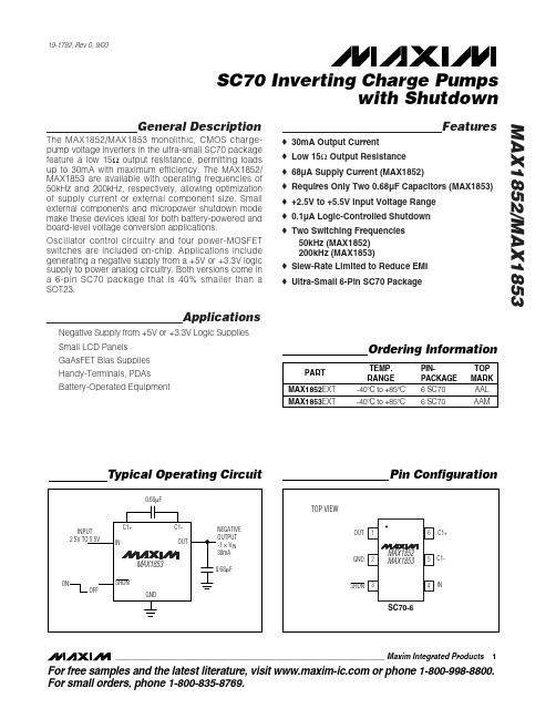
PART MAX1852EXT MAX1853EXT TEMP. RANGE -40°C to +85°C -40°C to +85°C PINPACKAGE 6 SC70 6 SC70 TOP MARK AAL AAM
Ordering Information
Typical Operating Circuit
Note 1: All devices arA = +25°C. All temperature limits are guaranteed by design. Note 2: Output resistance is guaranteed with capacitor ESR of 0.3Ω or less.
2
_______________________________________________________________________________________
元器件交易网
SC70 Inverting Charge Pumps with Shutdown MAX1852/MAX1853
元器件交易网
19-1792; Rev 0; 9/00
SC70 Inverting Charge Pumps with Shutdown
Motorola 3.5 kHz 产品说明书
RVN4126 3.59100-386-9100-386/T DEVICERVN41772-CD2-3.5MCS/MTSRVN41821-CD2-3.5XTS3000/SABER PORTABLE YES RKN4046KHVN9085 3.51-20 R NO HLN9359 PROG. STAND RVN4057 3.532 X 8 CODEPLUG NO3080385B23 & 5880385B30 MDVN4965 3.59100-WS/T CONFIG KITRVN4053 3.5ASTRO DIGITAL INTERFACE NO3080385B23RVN41842-CD RKN4046A (Portable) 2-3.5ASTRO PORTABLE /MOBILE YES3080369B73 or0180300B10 (Mobile) RVN41831-CD3080369B732-3.5ASTRO SPECTRA MOBILE YES(Low / Mid Power)0180300B10 (High Power) RVN4185CD ASTRO SPECTRA PLUS MOBILE NO MANY OPTIONS; SEESERVICE BRIEF#SB-MO-0101RVN4186CD ASTRO SPECTRA PLUS MANY OPTIONS;MOBILE/PORTABLE COMB SEE SERVICE BRIEF#SB-MO-0101RVN4154 3.5ASTROTAC 3000 COMPAR.3080385B23RVN5003 3.5ASTROTAC COMPARATORS NO3080399E31 Adpt.5880385B34RVN4083 3.5BSC II NO FKN5836ARVN4171 3.5C200RVN4029 3.5CENTRACOM SERIES II NO VARIOUS-SEE MANUAL6881121E49RVN4112 3.5COMMAND PLUS NORVN4149 3.5COMTEGRA YES3082056X02HVN6053CD CT250, 450, 450LS YES AAPMKN4004RVN4079 3.5DESKTRAC CONVENTIONAL YES3080070N01RVN4093 3.5DESKTRAC TRUNKED YES3080070N01RVN4091 3.5DGT 9000 DESKSET YES0180358A22RVN4114 3.5GLOBAL POSITIONING SYS.NO RKN4021AHVN8177 3.5GM/GR300/GR500/GR400M10/M120/130YES3080070N01RVN4159 3.5GP60 SERIES YES PMLN4074AHVN9128 3.5GP300 & GP350RVN4152 3.5GP350 AVSRVN4150 3.5GTX YES HKN9857 (Portable)3080070N01(Mobile) HVN9025CD HT CDM/MTX/EX SERIES YES AARKN4083/AARKN4081RiblessAARKN4075RIBLESS NON-USA RKN4074RVN4098H 3.5HT1000/JT1000-VISAR YES3080371E46(VISAR CONV)RVN4151 3.5HT1000 AVSRVN4098 3.5HT1000/ VISAR CONV’L.YES RKN4035B (HT1000) HVN9084 3.5i750YES HLN-9102ARVN4156 3.5LCS/LTS 2000YES HKN9857(Portable)3080070N01(Mobile) RVN4087 3.5LORAN C LOC. RECV’R.NO RKN4021ARVN4135 3.5M100/M200,M110,M400,R100 includesHVN9173,9177,9646,9774YES3080070N01RVN4023 3.5MARATRAC YES3080070N01RVN4019 3.5MAXTRAC CONVENTIONAL YES3080070N01RVN4139 3.5MAXTRAC LS YES3080070N01RVN4043 3.5MAXTRAC TRK DUPLEX YES3080070N01RVN4178CD MC SERIES, MC2000/2500DDN6124AW/DB25 CONNECTORDDN6367AW/DB9 CONNECTOR RVN41751-CD Rib to MIC connector 1-3.5MCS2000 RKN4062BRVN41131-3.5MCS2000RVN4011 3.5MCX1000YES3000056M01RVN4063 3.5MCX1000 MARINE YES3000056M01RVN4117 3.5MDC/RDLAP DEVICESRVN4105 3.5MOBILE PROG. TOOLRVN4119 3.5MOBITEX DEVICESRVN4128 3.5MPT1327-1200 SERIES YES SEE MANUALRVN4025 3.5MSF5000/PURC/ANALOG YES0180355A30RVN4077 3.5MSF5000/10000FLD YES0180355A30RVN4017K 3.5MT 1000YES RTK4205CRVN4148 3.5MTR 2000YES3082056X02RVN4140 3.5MTRI 2000NORVN41761-CD MTS2000, MT2000*, MTX8000, MTX90001-3.5*programmed by DOS which is included in the RVN4176RVN4131 3.5MTVA CODE PLUG FIXRVN4142 3.5MTVA DOCTOR YES3080070N01RVN4131 3.5MTVA3.EXERVN4013 3.5MTX800 & MTX800S YES RTK4205CRVN4097 1-CD MTX8000/MTX9000,MTS2000,MT2000*,* programmed by DOS which is included in the RVN4176HVN9067CD MTX850/MTX8250MTX950,MTX925RVN4138 3.5MTX-LS YES RKN4035DRVN4035 3.5MX 1000YES RTK4203CRVN4073 3.5MX 800YES RKN4006BHVN9395 P100, P200 LB, P50+, P210, P500, PR3000RVN4134 3.5P100 (HVN9175)P200 LB (HVN9794)P50+ (HVN9395)P210 (HVN9763)P500 (HVN9941)PR3000 (HVN9586)YES RTK4205HVN9852 3.5P110YES HKN9755A/REX1143 HVN9262 3.5P200 UHF/VHF YES RTK4205RVN4129 3.5PDT220YVN4051 3.5PORTABLE REPEATER Portable rptr.P1820/P1821AXRVN4061C 3.5PP 1000/500NO3080385B23 & 5880385B30 RVN5002 3.5QUANTAR/QUANTRO NO3O80369E31RVN4135 3.5R100 (HVN9177)M100/M200/M110/M400YES0180358A52RVN4146 3.5RPM500/660RVN4002 3.5SABER YES RTK4203CRVN4131 3.5SETTLET.EXEHVN9007 3.5SM50 & SM120YESRVN4039 3.5SMART STATUS YES FKN5825AHVN9054 3.5SOFTWARE R03.2 P1225YES3080070N01HVN9001 3.5SOFTWARE R05.00.00 1225LS YES HLN9359AHVN9012 3.5SP50RVN4001N 3.5SPECTRA YES3080369B73 (STANDARD)0180300B10 (HIGH POWER) RVN4099 3.5SPECTRA RAILROAD YES3080369B73RVN4110 3.5STATION ACCESS MODULE NO3080369E31RVN4089A 3.5STX TRANSIT YES0180357A54RVN4051 3.5SYSTEMS SABER YES RTK4203BRVN4075 3.5T5600/T5620 SERIES NO3080385B23HVN9060CD TC3000, TS3000, TR3000RVN4123 3.5VISAR PRIVACY PLUS YES3080371E46FVN4333 3.5VRM 100 TOOLBOX FKN4486A CABLE &ADAPTORRVN4133 3.5VRM 500/600/650/850NORVN4181CD XTS 2500/5000 PORTABLES RKN4105A/RKN4106A RVN41002- 3.5XTS3000 ASTRO PORTABLE/MOBILERVN4170 3.5XTS3500YES RKN4035DRIB SET UPRLN4008E RADIO INTERFACE BOX (RIB)0180357A57RIB AC POWER PACK 120V0180358A56RIB AC POWER PACK 220V3080369B71IBM TO RIB CABLE (25 PIN) (USE WITH XT & PS2)3080369B72IBM TO RIB CABLE (9 PIN)RLN443825 PIN (F) TO 9 PIN (M) ADAPTOR (USE W/3080369B72 FOR AT APPLICATION) 5880385B308 PIN MODULAR TO 25 PIN ”D” ADAPTOR (FOR T5600 ONLY)0180359A29DUPLEX ADAPTOR (MOSTAR/TRAXAR TRNK’D ONLY)Item Disk Radio RIB Cable Number Size Product Required Number Item Disk Radio RIB Cable Number Size Product Required NumberUtilizing your personal computer, Radio Service Software (RSS)/Customer Programming Software (CPS)/CustomerConfiguration Software (CCS) enables you to add or reprogram features/parameters as your requirements change. RSS/CPS/CCS is compatible with IBM XT, AT, PS/2 models 30, 50, 60 and 80.Requires 640K RAM. DOS 3.1 or later. Consult the RSS users guide for the computer configuration and DOS requirements. (ForHT1000, MT/MTS2000, MTX838/8000/9000, Visar and some newer products —IBM model 386, 4 MEG RAM and DOS 5.0 or higher are recommended.) A Radio Interface Box (RIB) may be required as well as the appropriate cables. The RIB and cables must be ordered separately.Licensing:A license is required before a software (RVN) order is placed. The software license is site specific (customer number and ultimate destination tag). All sites/locations must purchase their own software.Be sure to place subsequent orders using the original customer number and ship-to-tag or other licensed sites; ordering software without a licensed customer number and ultimate tag may result in unnecessary delays. To obtain a no charge license agreement kit, order RPX4719. To place an order in the U.S. call 1-800-422-4210. Outside the U.S., FAX 847-576-3023.Subscription Program:The purchase of Radio ServiceSoftware/Customer Programming/Customer ConfigurationSoftware (RVN & HVN kits) entitles the buyer/subscriber to three years of free upgrades. At the end of these three years, the sub-scriber must purchase the same Radio Service Software kit to receive an additional three years of free upgrades. If the sub-scriber does not elect to purchase the same Radio Service Software kit, no upgrades will be sent. Annually a subscription status report is mailed to inform subscribers of the RSS/CPS/CCS items on our database and their expiration dates.Notes:1)A subscription service is offered on “RVN”-Radio Service Software/Customer Programming/Customer Configuration Software kits only.2)“RVN” software must only be procured through Radio Products and Services Division (RPSD). Software not procured through the RPSD will not be recorded on the subscription database; upgrades will not be mailed.3)Upgrades are mailed to the original buyer (customer number & ultimate tag).4)SP software is available through the radio product groups.The Motorola General Radio Service Software Agreement is now available on Motorola Online. If you need assistance please feel free to submit a “Contact Us” or call 800-422-4210.SMART RIB SET UPRLN1015D SMART RIB0180302E27 AC POWER PACK 120V 2580373E86 AC POWER PACK 220V3080390B49SMARTRIB CABLE (9 PIN (F) TO 9 PIN (M) (USE WITH AT)3080390B48SMARTRIB CABLE (25 PIN (F) TO 9 PIN (M) (USE WITH XT)RLN4488ASMART RIB BATTERY PACKWIRELESS DATA GROUP PRODUTS SOFTWARERVN4126 3.59100-386/9100T DEVICES MDVN4965 3.59100-WS/T CONFIG’TN RVN41173.5MDC/RDLAP DEVICESPAGING PRODUCTS MANUALS6881011B54 3.5ADVISOR6881029B90 3.5ADVISOR ELITE 6881023B20 3.5ADVISOR GOLD 6881020B35 3.5ADVISOR PRO FLX 6881032B30 3.5BR8506881032B30 3.5LS3506881032B30 3.5LS5506881032B30 3.5LS7506881033B10 3.5LS9506881035B20 3.5MINITOR III8262947A15 3.5PAGEWRITER 20008262947A15 3.5PAGEWRITER 2000X 6881028B10 3.5TALKABOUT T3406881029B35 3.5TIMEPORT P7308262947A15 3.5TIMEPORT P930NLN3548BUNIVERSAL INTERFACE KITItem Disk Radio NumberSize Product。
DS1856B-020R中文资料

Operating Temperature Range ...........................-40°C to +95°C Programming Temperature Range .........................0°C to +70°C Storage Temperature Range .............................-55°C to +125°C Soldering Temperature .......................................See IPC/JEDEC J-STD-020A
1
For pricing delivery, and ordering information please contact Maxim/Dallas Direct! at 1-888-629-4642, or visit Maxim’s website at .
元器件交易网
Pin Configurations
TOP VIEW A SDA 1 IN1 SCL VCC H1 SCL 2 OUT1 3 L1 IN1 4 16 VCC 15 H1 14 L1
TO LASER BIAS CONTROL TO LASER MODULATION CONTROL
DS1856
L0
B
OUT2
Stresses beyond those listed under “Absolute Maximum Ratings” may cause permanent damage to the device. These are stress ratings only, and functional operation of the device at these or any other conditions beyond those indicated in the operational sections of the specifications is not implied. Exposure to absolute maximum rating conditions for extended periods may affect device reliability.
Maxi Heat 500IQ SERIAL NUMBER 14-000001 AND UP MH5

MH500 IQ Specs●Btu per burner- 515,000●CFM per burner- 3200●Fuel consumption per burner- 3.65 Gal/h●Recommended fuel consumption- K-1 Kerosene or No.1 Diesel●Operating power per burner- ~115 V, 1-PH, 60Hz 24 A (MAX 82 A)●Weight per burner- 357 lbs●Nozzles per burner- 2 GPH 60` Delavan Type A & 1 GPH 60` Delavan Type W ●Operating fuel pressure- 145 PSI/ 1000 kpa/ 10 barOverviewThe IQ system is a design that allows for the simplicity and ease ofoperation. At start up the IQ system will calibrate for the ambient air temperature and elevation to determine the air to fuel ratio setting for theair band. There are no more calibrations needed after this point and the IQsystem will recalculate the airband adjustment as ambient temperaturechanges.Control Screen Flickering/ Turning off & On❏The screen is a 12 volt system and receives power from the transformer box next to the IQ controller. Check power at the two terminal wires (blk & white) going into the right side of the IQ control. Check all connections on the main PC board and fuses.❏Check the Voltage regulator in the control box below Image (A). Make sure all voltage is proper.❏Make sure the rocker switch on the heater outlet door is working (Picture below).The switch is a two pole switch that closes once the door is opened. Power is sent to the screen for illumination.❏❏❏If the problem persists and power at the converter box showing 12 volts to the screen, then replace the screen.Engine Does Not Run**M axi Heat 500IQ will not start ( The engine will crank over ,but not run) Isuzu GensetNote:I f the unit has a shocker valve, check the value and make sure the shocker is open.** ❏Ensure the unit has enough fuel.❏Go through and check all the connections and most importantly check the emergency shutdown connection to make sure the connection is secure.(IsuzuEngine Timer Module-921432/ Cat C1.5 T4F- 650302)❏If all connections are secure then check to see if the engine is getting fuel.❏Pull the return line on the fuel pump and turn the engine over to see if the fuel pump is working correctly. Loosen the injector line at the injector to see if there is further fuel flow.❏The unit is getting fuel and the Fuel pump is working, find the fuel solenoid on the engine. Check the fuel shut off solenoid to ensure plunger retracts (example “A”, solenoid plunger retracts from voltage on hold wire)❏If the pump works when an auxiliary power source is applied then trace through wiring for loss of voltage. Power is pulled from the engine starter and goesthrough the temp and oil pressure switches. Check schematic for further testing.❏Burner Cycles On & Off**Maxi Heat 500IQ has one burner that will begin to run and then shuts down for High Temp Fault. ( Message appears on the IQ screen).**❏Each burner or both cycling on and off indicates that there is a possibility of backpressure. Back pressure occurs when the flow of heat is restricted and notmoved which accumulates at the outlet or in the burner itself. Kinks in the ducting can cause this issue. Make sure the ducting is straight with limited bends and no elevated lifts or descending of the ducting.❏Check ducting for proper flow.❏Ensure the high limit sensor is working at the end of the outlet.❏Check the main blower fans connection and ensure it is turning on as needed.Faulty connections or loss of power can cause a stall in fan operation which inturn causes the heater to increase temperature.❏Make sure heat going into the area is ventilated so heat does not accumulate and raises temperature to increase output.Blower Fan Stops Circulating or gets a Red “X” over fan:**MH 500 IQ has a burner that will start up and the fan will not turn on. Fan not running will cause the unit to shut down.**❏When this fault occurs it is an indication the fan is losing power.❏Check all the circuits to the fan. Power comes from 120 plug in into the bottom of the IQ controller.❏Start with going to the IQ control box for the burner that is having the issue. Open the cover of the box and over to the side is a wrench icon, press it. After pressing the icon type the password 123 then press the Enter button. You can control the fan manually from this point.❏Note: If you turn the fan on manually and the fan doesn't run, then the motor for the fan could be faulty and need to be replaced (#107194) ❏If the fan runs while in manual mode then the fan is working and power going to fan is ok. The circuit into the IQ controller that controls the blower fan has a loose or faulty connection.❏Check the red terminal block at the bottom of the IQ controller (See examples below). 120 volts into the terminal block feeds the relay above it and into the fan circuit during the purge process.No Power To IQ Control**Maxi Heat 500IQ Controller does not turn on or has no power to the IQ box.**❏No power into the IQ controller will not activate the LCD screen for further operation. Make sure the door on the outlet (heat out of burner) side isopen. The micro switch in the corner of the door activates power to eachscreen. * Switch is a two pole switch, if one side fails then the other couldstill open and provide power to the other screen.*❏Check the relay in the transformer box next to the controller (Example “A”). Make sure connections are secure and the relay is functioningproperly.❏Check the heater element on top of the fuel water separator filter. If element shorts then it will draw too much amperage and not allow thescreen to power up.❏If the IQ controller has 12 volts on the two wire ( example “B” below) harnesses into the side of the controller. If the wire has 12 volts then thescreen needs to be replaced.❏Example “A”Example “B”❏Burner shuts off for “Burner Power Break” or will not turn on**Burner shuts off or always seeing “Burner Power Break “ fault on screen.**❏During the purge cycle at the initial start up the burner ignitor box receives all its power from the IQ controller. System is 120 volts and is used topower the burner and fuel system.❏“Power Break” refers to the break in power to the burner. Test for loss of voltage at the Ignitor box in the burner assembly. (See example “B”) ❏Terminal “N” & “L” are power in. If there is no voltage then check the IQ controller for power loss. Power into the controller red terminal blockdistributes voltage to the fan and burner.❏Check the red terminal block for power in and out (120 v). Make sure connections are secure.❏Check the 15 amp fuse on the left of the controller. (Example “C”). If it fails, replace it.❏Test for voltage into the power relay above the red terminal block. During purge power goes to relay and out into the thermal breaker. (Example“C”). If failed, replace it.Example “B”Reset Safety Thermostat fault:**Safety thermostat is a protection for the high limit. If the fan has failed or heater shut down incorrectly it creates trapped heat which trips the thermostat.**❏Look for the black cap on the heat exchanger below the main blower fan.(Example “A”)❏Remove the cap and you will expose a red button. This button isconnected to the safety thermostat and has to be reset. Push and hold forfive seconds.❏If the thermostat continues to trip then give it 5 to 10 minutes for the heat to dissipate.❏If the problem persists then replace the safety thermostat.❏Burner starts to smoke and build black smoke out of exhaust stack:** Black smoke is an indication the unit is not getting enough air, bad fuel or carbon build up in the chamber.**❏Make sure air setting is on a specified number that the IQ controller recommends at the time of start up. D O NOT adjust air setting duringoperation unless the IQ controller specifies. (Any change of ambienttemperature and elevation requires smaller or higher amounts of airmixture.)❏Check for any debris or material covering or blocking the air damper.Clean and clear.❏Check fuel pressure and maintain 140-145 PSI at the pump.❏Ensure fuel nozzle NO 1 & NO 2 are both clean and working correctly.Check the schematic for a list of wiring for each nozzle. IQ logic controlsboth nozzles to maintain temperature.❏Make sure the heat exchanger and burn chamber are clear of any soot build up. If there is a large amount of build up then take the burner apartand wash with hot water high pressure hose. Let the barrel air dry beforeusing.❏Make sure only NO 1 Diesel fuel is used. Any additives can cause more gel-like substances which will create fuel issues.Filters perengine option:MH 500IQ MCS W/ ISUZU T4F 3CE1BurnerFUEL FILTER (35MICRON) 107222 ****MH**\ 14-******EngineAIR FILTER 650290 ****MH**\ 14-****** OIL FILTER 22-000309 ****MH**\ 14-****** FUEL FILTER 22-000310 ****MH**\ 14-******FILTER KIT (ALLFILTERS) 108461 ****MH**\ 14-******MH 500IQ MCS W/ CAT 1.5 NA T4FFUEL FILTER (35MICRON ) 107222 ****MH**\ 14-******EngineAIR FILTER 102580 ****MH**\ 14-****** OIL FILTER 650304 ****MH**\ 14-****** FUEL FILTER 103155 ****MH**\ 14-******FILTER KIT (ALLFILTERS) 108464 ****MH**\ 14-******Oil Change Intervals:Caterpillar C1.5- Every 500 hoursIsuzu 3CE1- Every 500 hoursIsuzu T4F 3CE1 Parts:●Dipstick Tube EXT Assy- ( 100604 )●Starter-102465●AVR Board-103016●Stop Solenoid--22-000316●Stop Solenoid O Ring- 22-000329●Alternator Diode- 22-000324●Temp Switch- 22-000325●Oil Pressure Switch- 22-000326●Relay Assembly- 650423●Fuel Pump- 22-000317●Auto Shutdown Timer-921432●Filter Kit (Air Fuel & Oil)- 108959●Fuel Water Separator ( 35 Micron Fuel Filter)- 107222●Timer Module-921432Cat 1.5 T4F Parts:●Ignition Keys- 920474●Ignition/Cat- 920475●Hour Meter- 340014●Timer/Shutdown- 650302●Cat 1.5 Muffler-104867●Muffler Gasket- 650234● 3 way Fuel Gauge- 103205●Filter Kit (Air Fuel & Oil)- 108961●Fuel Water Separator ( 35 Micron Fuel Filter)- 107222●Timer Shutdown-650302*Check engine operators manual for specific recommended lubricants.*Additional warranty information & claim forms can be obtained on .*Please contact Allmand Tech line for additional help and troubleshooting @ (308)995-3431 / Parts (800) 562-1373.。
Maxi-Power 1938年成立的轻型汽机生成器的商品说明书

Reliability, Performance and Integrity.SINCE 1938Maxi-Power™Mobile GeneratorSOUND ATTENUATEDHEAVY-DUTY , OVER-SIZED ALTERNATOR HIGH CAPACITY , COLD START BATTERY AUTOMATIC VOLTAGE REGULATOR (AVR)120 VOLT GFCI RECEPTACLES ALWAYSENERGIZED WHILE RUNNING ADJUSTABLE COUPLER CHANNEL FREQUENCY SWITCH TO RUN 50 Hz OR 60 HzKEY FEATURES110% Full Fluid ContainmentOversized Electrical LugsLarge Capacity Fuel Tank¹Standard External Fuel ConnectionsStandard Programmable Start/Stop for Standby Applications Electric Fuel Primer & Air-Bleed (EFPA) PumpHydraulic Surge Brakes StandardLockable Switch / Voltage SelectorCurbside Fluid Maintenance / Side Fork Pockets (MP25)Trailer DOT Compliant 49 CFRTrailer OptionalWarranty Coverage / Product: 2 Years/2,000 Hour Limited Warranty* GPS ReadyMP-0718Reliability, Performance and Integrity.SINCE 1938WHY ALLMAND ®■ Interchangeable electrical connectors thatcan be used in either single or three phase modes ■ Single set of 5 CamlocksOPTIONSCamlocks■ 50 W 120 V battery heater pad■ 1,000 W 120 V thermosiphon block heater with thermostat to maintain temperature■ 5 A 120 V with 3 stage charge cycleArctic PackageBattery Charger (MP25 Only)Lockable Battery Disconnect (MP25 Only)Electric Brake on MP65Holdrege, Nebraska 68949P: (800) 562-1373 • F: (308) When it comes to managing a jobsite, you wantequipment that will not fail you when you need it most. You’re looking for trust and reliability. Allmand ® brings that to your jobsite, with over 75 years of respected experience. Our focus on Service and Support allowsusers to get the parts, technical service and support they need. Product innovation has helped us develop state-of-the-art towable jobsite equipment, bringing portable light towers, mobile industrial heaters, portable light stands, portable air compressors and mobile generators for the construction, mining, oil & gas, and rental markets.。
林肯电气(Lincoln Electric)机械组装说明书

1 XX
1 FEED PLATE
0744-000-178R
1 XX
2 FIXING ARM COMPL.
0646-233-015R
1 XX
3 AXIS DRIVE ROLL L
0646-233-039R
1 XX
Spare Parts - Electrical Schematic
2
Spare Parts - Electrical Schematic
ASSEMBLY PAGE NAME
CODE NO.: 50215 50216
K NO.: K10406 K10407
FIGURE NO.: LINC FEED 37 LINC FEED 38
A
B
1
1
2
2
39 38 37 36 33 10
12
11 9
2
7
6
5
8
1
4
27
3
28
16 13
17 34 35
18 19 15
14
15 20
22
25
26 21
29
30 31 3
32
24 23
Figure A
Figure A: Machine Assembly
Item Description
Part Number
QTY 1 2 3 4 5 6 7
1 FRONT PANEL
R-3019-016-1/08R
1 XX
1 XX
1 XX 1 XX 3 XX 1 XX 1 XX 1 XX 1 XX 1 XX 1 XX 1 XX 1 XX 1 XX 1 XX 1 XX 1 XX 1 XX 1 XX 1 XX 1 XX 1 XX 1 XX 1 XX 1 XX 1 XX 1 XX 1 XX 1 XX 1 XX 1 XX
- 1、下载文档前请自行甄别文档内容的完整性,平台不提供额外的编辑、内容补充、找答案等附加服务。
- 2、"仅部分预览"的文档,不可在线预览部分如存在完整性等问题,可反馈申请退款(可完整预览的文档不适用该条件!)。
- 3、如文档侵犯您的权益,请联系客服反馈,我们会尽快为您处理(人工客服工作时间:9:00-18:30)。
General DescriptionThe MAX1856 offers a low-cost solution for generating a SLIC (ringer and off-hook) power supply. Using standard off-the-shelf transformers from multiple vendors, the MAX1856 generates various output voltages: -24V and -72V (dual output) for both ringer and off-hook supplies for voice-enabled broadband consumer premises equipment (CPE), -48V for IP phones and routers, -5V and -15V (sin-gle or dual output) for DSL CO line drivers, or negative voltages as high as -185V for MEMS bias supplies. The output voltages are adjusted with an external voltage divider.Due to its wide operating voltage range, the MAX1856operates from a low-cost, unregulated DC power supply for cost-sensitive applications like xDSL, cable modems,set-top boxes, LMDS, MMDS, WLL, and FTTH CPE. The MAX1856 provides low audio-band noise for talk battery and a sturdy output capable of handling the ring trip con-ditions for ring battery.The operating frequency can be set between 100kHz and 500kHz with an external resistor in free-running mode. For noise-sensitive applications, the MAX1856’s operating fre-quency can be synchronized to an external clock over its operating frequency range.The flyback topology allows operation close to 50% duty cycle, offering high transformer utilization, low ripple cur-rent, and less stress on input and output capacitors.Internal soft-start minimizes startup stress on the input capacitor, without any external components.The MAX1856’s current-mode control scheme does not require external loop compensation. The low-side current-sense resistor provides accurate current-mode control and overcurrent protection.ApplicationsVoIP Ringer and Off-Hook Voltage Generators Cable and DSL Modems Set-Top BoxesWireless Local Loop FTTHLMDS/MMDS RoutersIndustrial Power Supplies CO DSL Line Driver Supplies MEMS Bias SuppliesFeatureso Low-Cost, Off-the-Shelf Transformer o 3V to 28V Input Rangeo Low Audio-Band Noise on Talk Battery o Effectively Handles Ring Trip Transients o Powers 2-, 4-, or 12-Line Equipment o High Efficiency Extends Battery Life During Life-Line Support Conditions o Adjustable 100kHz to 500kHz Switching Frequency o Clock Synchronization o Internal Soft-Starto Current-Mode PWM and Idle Mode™Control Scheme o Logic-Level Shutdown o 10-Pin µMAX PackageMAX1856Wide Input Range, Synchronizable,PWM SLIC Power Supply________________________________________________________________Maxim Integrated Products1Typical Operating CircuitOrdering Information19-1898; Rev 0; 2/01For price, delivery, and to place orders,please contact Maxim Distribution at 1-888-629-4642,or visit Maxim’s website at .Idle Mode is a trademark of Maxim Integrated Products.M A X 1856Wide Input Range, Synchronizable,PWM SLIC Power SupplyABSOLUTE MAXIMUM RATINGSELECTRICAL CHARACTERISTICS(V CC = SYNC/SHDN,V CC = 5V, V LDO = 5V, R OSC = 200k Ω, T A = 0°C to +85°C . Typical values are at T A = +25°C, unless otherwise noted.)Stresses beyond those listed under “Absolute Maximum Ratings” may cause permanent damage to the device. These are stress ratings only, and functional operation of the device at these or any other conditions beyond those indicated in the operational sections of the specifications is not implied. Exposure to absolute maximum rating conditions for extended periods may affect device reliability.V CC , SYNC/SHDN to GND.....................................-0.3V to +30V PGND to GND .......................................................-0.3V to +0.3V LDO, FREQ, FB, CS to GND.....................................-0.3V to +6V EXT, REF to GND......................................-0.3V to (V LDO + 0.3V)LDO Output Current............................................-1mA to +20mA LDO Short Circuit to GND...............................................<100ms REF Short Circuit to GND...........................................ContinuousContinuous Power Dissipation (T A = +70°C)10-Pin µMAX (derate 5.6mW/°C above +70°C)...........444mW Operating Temperature Range ...........................-40°C to +85°C Junction Temperature......................................................+150°C Storage Temperature Range.............................-65°C to +150°C Lead Temperature (soldering, 10s).................................+300°CMAX1856Wide Input Range, Synchronizable,PWM SLIC Power Supply_______________________________________________________________________________________3ELECTRICAL CHARACTERISTICS (continued)(V CC = SYNC/SHDN,V CC = 5V, V LDO = 5V, R OSC = 200k Ω, T A = 0°C to +85°C . Typical values are at T A = +25°C, unless otherwise noted.)M A X 1856Wide Input Range, Synchronizable,PWM SLIC Power Supply 4_______________________________________________________________________________________ELECTRICAL CHARACTERISTICS (continued)(V CC = SYNC/SHDN,V CC = 5V, V LDO = 5V, R OSC = 200k Ω, T A = -40°C to +85°C , unless otherwise noted.) (Note 3)Note 2:The reference output voltage (V REF ) is measured with respect to FB. The difference between REF and FB is guaranteed tobe within these limits to ensure output voltage accuracy.Note 3:Specifications to -40°C are guaranteed by design, not production tested.Typical Operating Characteristics(Circuit of Figure 1, V CC = V SYNC/SHDN = 12V, V OUT1= -24V, V OUT2= -72V, R OSC = 200k Ω, unless otherwise noted.)-24.5-24.0-23.0-23.5-22.5-22.00200100300400500600700-24V OUTPUT VOLTAGE vs. LOAD CURRENTI OUT1 (mA)V O U T 1 (V )-74.5-74.0-73.0-73.5-72.5-72.00200100300400500600700-72V CROSS-REGULATION VOLTAGEvs. LOAD CURRENTI OUT1 (mA)V O U T 2 (V )5060709080100100200300400500600700EFFICIENCY vs. LOAD CURRENT(-24V OUTPUT)I OUT1 (mA)E F F I C I E N C Y (%)MAX1856Wide Input Range, Synchronizable,PWM SLIC Power Supply_______________________________________________________________________________________5-24.0-23.8-23.4-23.6-23.2-23.0105152025-24V OUTPUT VOLTAGE vs. INPUT VOLTAGEV IN (V)V O U T 1 (V )-73.0-72.6-71.8-72.2-71.4-71.0105152025-72V OUTPUT VOLTAGE vs. INPUT VOLTAGEV IN (V)V O U T 1 (V )5060708090100105152025DUAL-OUTPUT EFFICIENCY vs. INPUT VOLTAGEV IN (V)E F F I C I E N C Y (%)-48.5-48.1-47.7-47.3-46.9-46.5100200300400-48V OUTPUT VOLTAGE vs. LOAD CURRENTI OUT2 (mA)V O U T 2 (V )50607080901000100200300400EFFICIENCY vs. LOAD CURRENT(-48V OUTPUT)I OUT2 (mA)E F F I C I E N C Y (%)5015010020025010515202530SUPPLY CURRENT vs. INPUT VOLTAGEINPUT VOLTAGE (V)S U P P L Y C U R R E N T (µA )Typical Operating Characteristics (continued)(Circuit of Figure 1, V CC = V SYNC/SHDN = 12V, V OUT1= -24V, V OUT2= -72V, R OSC = 200k Ω, unless otherwise noted.)-74-73-72-71-70050100150200250-72V OUTPUT VOLTAGE vs. LOAD CURRENTI OUT2 (mA)V O U T 2 (V )-24.0-23.8-23.4-23.6-23.2-23.010050150200250-24V CROSS-REGULATION VOLTAGEvs. LOAD CURRENTI OUT2 (mA)V O U T 1 (V )506070809010010050150200250EFFICIENCY vs. LOAD CURRENT(-72V OUTPUT)I OUT2 (mA)E F F I C I E N C Y (%)M A X 1856Wide Input Range, Synchronizable,PWM SLIC Power Supply 6_______________________________________________________________________________________Typical Operating Characteristics (continued)(Circuit of Figure 1, V CC = V SYNC/SHDN = 12V, V OUT1= -24V, V OUT2= -72V, R OSC = 200k Ω, unless otherwise noted.)1.2401.2501.2451.2551.260REFERENCE VOLTAGE vs. REFERENCE CURRENTM A X 1856 t o c 16REFERENCE CURRENT (µA)V R E F (V )2001003005004001.2401.2501.2451.2551.260REFERENCE VOLTAGE vs. TEMPERATURETEMPERATURE (°C)V R E F (V )-4010-1535856010001001001000SWITCHING FREQUENCY vs. R OSCM A X 1856 t o c 18R OSC (k Ω)S W I T C H I N G F R E Q U E N C Y (k H z )0200100400300500600-4010-15356085SWITCHING FREQUENCY vs. TEMPERATURETEMPERATURE (°C)S W I T C H I N G F R E Q U E N C Y (k H z )700.1110EXT RISE/FALL TIME vs. CAPACITANCE10CAPACITANCE (nF)E X T R I S E /F A L L T I M E (n s )3050604020150190270230310350-4010-15356085SUPPLY CURRENT vs. TEMPERATURETEMPERATURE (°C)S U P P L Y C U R R E N T (µA )0.51.01.52.02.53.03.54.0010515202530SHUTDOWN CURRENT vs. INPUT VOLTAGEINPUT VOLTAGE (V)S H U T D O W N C U R R E N T (µA )50150100200250426810LDO DROPOUT VOLTAGE vs. LOAD CURRENTI LDO (mA)D R O P O U T V O L T A GE (V )A. V OUT = -48V, I OUT = 200mA, 50mV/divB. I LP , 2A/divCIRCUIT OF FIGURE 4HEAVY-LOAD SWITCHING WAVEFORMMAX1856 toc23-47.2V -47.0V-47.1V2A 02.0µs/divAB4AA. V OUT = -48V, I OUT = 20mA, 20mV/divB. I LP , 2A/divCIRCUIT OF FIGURE 4LIGHT-LOAD SWITCHING WAVEFORMMAX1856 toc24-47.80V -47.72V-47.76V2A 04µs/divABMAX1856Wide Input Range, Synchronizable,PWM SLIC Power Supply_______________________________________________________________________________________7Typical Operating Characteristics (continued)(Circuit of Figure 1, V CC = V SYNC/SHDN = 12V, V OUT1= -24V, V OUT2= -72V, R OSC = 200k Ω, unless otherwise noted.)A. I OUT = 20mA TO 200mA, 200mA/divB. VOUT , = -48V, 500mV/div C. I LP , 2A/divCIRCUIT OF FIGURE 4LOAD TRANSIENTMAX1856 toc25-47.6V 01ms/divAB200mA-47.1V-48.1VC-100-60-80-20-402006040050100150200250RINGER TO TALK-BATTERY CROSSTALKFREQUENCY (Hz)(d B)A. V IN = 10V TO 14V, 2VdivB. V OUT= -48V, I OUT = 200mA, 100mV/div CIRCUIT OF FIGURE 4LINE TRANSIENTMAX1856 toc2614V 10V400µs/divAB12V -47VA. V SYNC /SHDN = 0 TO 5V, 5V/divB. I LP , 2A/divC. V OUT = -48V, R OUT = 2.4k Ω, 20V/div CIRCUIT OF FIGURE 4EXITING SHUTDOWNMAX1856 toc21-60V05V02A 0-20V -40V 4ms/divABC A. V SYNC /SHDN = 5V TO 0, 5V/div B. V EXT , 5V/div C. I LP , 2A/divV OUT = -48V, R OUT = 240ΩCIRCUIT OF FIGURE 4ENTERING SHUTDOWNMAX1856 toc225V 05V2A 010µs/divABCM A X 1856over a wide range of loads by employing both PWM operation and Maxim ’s proprietary Idle Mode control to minimize operating current at light loads. Other features include shutdown, adjustable internal operating fre-quency or synchronization to an external clock, soft-start, adjustable current limit, and a wide (3V to 28V)input range.PWM ControllerThe heart of the MAX1856 current-mode PWM con-troller is a BiCMOS multi-input comparator that simulta-neously processes the output-error signal, the current-sense signal, and a slope-compensation ramp (Figure 2). The main PWM comparator is direct sum-ming, lacking a traditional error amplifier and its associ-rent-mode operation where the duty ratio is set by the input-to-output voltage ratio and the transformer ’s turn ratio. The current-mode feedback loop regulates peak inductor current as a function of the output error signal.At light loads, the controller enters Idle Mode. During Idle Mode, switching pulses are provided only as nec-essary to supply the load, and operating current is min-imized to provide the best light-load efficiency. The minimum-current comparator threshold is 15mV, or 15% of the full-load value (I MAX ) of 100mV. When the controller is synchronized to an external clock, Idle Mode occurs only at very light loads.Wide Input Range, Synchronizable,PWM SLIC Power Supply 8_______________________________________________________________________________________Low-Dropout Regulator (LDO)All MAX1856 functions, including EXT, are internally powered from the on-chip, low-dropout 5V regulator.The regulator input is at V CC , while its output is at LDO.The V CC -to-LDO dropout voltage is typically 200mV (300mV max at 12mA), so that when V CC is <5.2V,V LDO is typically V CC - 200mV. When the LDO is in dropout, the MAX1856 still operates with V CC as low as 3V (as long as the LDO exceeds 2.7V), but with reduced amplitude FET drive at EXT. The maximum V CC input voltage is 28V.LDO can supply up to 12mA to power the IC, supply gate charge through EXT to the external FET, and sup-ply small external loads. When driving particularly large FETs at high switching rates, little or no LDO current may be available for external loads. For example, when switched at 500kHz, a large FET with 20nC gate charge requires 20nC ✕500kHz, or 10mA.Soft-StartThe MAX1856 features a “digital ” soft-start that is pre-set and requires no external capacitor. Upon startup,the peak inductor current increments from 1/5th of the value set by R CS , to the full current-limit value in five steps over 1024 cycles of f OSC or f SYNC . Additionally,the oscillator runs at 1/3 the normal operating frequen-cy (f OSC /3) until the output voltage reaches 20% of its nominal value (V FB ≤1.0V). See the Typical Operating Characteristics for a scope picture of the soft-start operation. Soft-start is implemented: 1) when power is first applied to the IC, 2) when exiting shutdown with power already applied, and 3) when exiting undervolt-age lockout. The MAX1856’s soft-start sequence does not start until V LDO reaches 2.5V.Design ProcedureThe MAX1856 can operate within a wide input voltage range from 3V to 28V. This allows it to be used with wall adapters. In applications driven by low-power, low-cost and low input and output ripple current requirements,the MAX1856 flyback topology can be used to gener-ate various levels of output voltages and multiple out-puts.Communications over the Internet interface with a stan-dard telephone connection, which includes the Subscriber Line Interface Circuit (SLIC). The SLIC requires a negative power supply for the audio and ringer functions. The circuits discussed here are designed for these applications. The following design discussions are related to the standard application cir-MAX1856Wide Input Range, Synchronizable,PWM SLIC Power Supply_______________________________________________________________________________________9Figure 1. Standard Application CircuitM A X 1856Wide Input Range, Synchronizable,PWM SLIC Power Supply 10______________________________________________________________________________________cuit (Figure 1) converting a +12V input to a -72V output (maximum load 100mA) and a -24V output (maximum load 400mA).Maximum Output PowerThe maximum output power the MAX1856 can provide depends on the maximum input power available and the circuit ’s efficiency:Furthermore, the efficiency and input power are both functions of component selection. Efficiency losses can be divided into three categories: 1) resistive losses across the transformer, MOSFET ’s on-resistance, cur-rent-sense resistor, and the ESR of the input and output capacitors; 2) switching losses due to the MOSFET ’s transition region, the snubber circuit, which also increases the transition times, and charging the MOS-FET ’s gate capacitance; and 3) transformer core loss-es. Typically, 80% efficiency can be assumed for initial calculations. The input power depends on the current limit, input voltage, output voltage, inductor value, the transformer ’s turns ratio, and the switching frequency:where N P :N S is the transformer ’s turns ratio.Setting the Operating Frequency(SYNC/SHDN and FREQ)The SYNC/SHDN pin provides both external-clock syn-chronization (if desired) and shutdown control. When SYNC/SHDN is low, all IC functions are shut down. A logic high at SYNC/SHDNselects operation at aP EFFICIENCY P OUT MAX IN MAX ()()=×MAX1856Wide Input Range, Synchronizable,PWM SLIC Power Supply______________________________________________________________________________________11100kHz to 500kHz frequency, which is set by a resistor (R OSC ) connected from FREQ to GND. The relationship between f OSC and R OSC is:Thus, a 250kH z operating frequency, for example, isset with R OSC = 200k Ω. At higher frequencies, the magnetic components will be smaller. Peak currents and, consequently, resistive losses will be lower at the higher switching frequency. However, core losses, gate charge currents, and switching losses increase with higher switching frequencies.Rising clock edges on SYNC/SHDN are interpreted as synchronization input. If the sync signal is lost while SYNC/SHDN is high, the internal oscillator takes over at the end of the last cycle, and the frequency is returned to the rate set by R OSC . If the signal is lost with SYNC/SHDN low, the IC waits for 50µs before shutting down. This maintains output regulation even with inter-mittent sync signals. When an external sync signal is used, Idle Mode switchover at the 15mV current-sense threshold is disabled so that Idle Mode only occurs at very light loads. Also, R OSC should be set for a fre-quency 15% below the SYNC clock rate:Setting the Output VoltageSet the output voltage using two external resistors form-ing a resistive divider to FB between the output and REF. First select a value for R3 between 3.3k Ωand 100k Ω. R1 is then given by:For a dual output as shown in Figure 1, a split feedback technique is recommended. Since the feedback volt-age threshold is 0, the total feedback current is:Since the feedback resistors are connected to the ref-erence, I TOTAL must be <400µA so that V REF is guaran-teed to be in regulation (see Ele ctrical Characte ristics Table ). Therefore, select R3 so the total current value isbetween 200µA and 250µA as shown in Figure 1. To ensure that the MAX1856 regulates both outputs with the same degree of accuracy over load, select the feedback resistors (R1 and R2) so their current ratio (I R1:I R2) equals the output power ratio (P OUT1:P OUT2)under full load:Once R3 and the dual feedback currents (I R1and I R2)are determined from the two equations above, use the following two equations to determine R1 and R2:Selecting the TransformerThe MAX1856 PWM controller works with economical off-the-shelf transformers. The transformer selection depends on the input-to-output voltage ratio, output current capacity, duty cycle, and oscillator frequency.Table 1 shows recommended transformers for the typi-cal applications, and Table 2 gives some recommend-ed suppliers.Transformer Turns RatioThe transformer turns ratio is a function of the input-to-output voltage ratio and maximum duty cycle. Under steady-state conditions, the change in flux density dur-ing the on-time must equal the return change in flux density during the off-time (or flyback period):For example, selecting a 50% duty cycle for the stan-dard application circuit (Figure 1) and a +12V inputvoltage, the -72V output requires a 1:6 turns ratio, and the -24V output requires a 1:2 turns ratio. Therefore, a transformer with a 1:2:2:2 turns ratio was selected.Primary inductanceThe average input current at maximum load can be cal-culated as:where η= efficiency. For V OUT = -24V, I OUT(MAX)=400mA, and V IN(MIN)= 10.8V as shown in Figure 1, thisM A X 1856Wide Input Range, Synchronizable,PWM SLIC Power Supply 12______________________________________________________________________________________52.5%, the average switch current (I SW(AVG)) is 2.114A.Choosing a primary inductance ripple current ∆I L to be 40% of the average switch current, the primary induc-tance is given by:Selecting f OSC = 250kH z and ∆I L = 0.4 x I SW(AVG)=0.846A, the primary inductance value is 27µH, and the peak primary current for this example is therefore 2.5A.Core SelectionThe transformer in a flyback converter is a coupled inductor with multiple windings on the same magnetic core. Flyback topologies operate by storing energy in the transformer magnetics during the on-time and transferring this energy to the output during the off-time.Core selection depends on the core ’s power-handling capability. The required output power is first consid-ered. For example, the standard application circuit requires 9.6W. Assuming a typical 80% efficiency, the transformer must support 12W of power. The core material ’s properties, the core ’s shape, and the size of the air gap determine the core ’s power rating. Since the equations relating these properties to the power capa-bility are involved, manufacturers simply provide charts giving “Power vs. Frequency ” for different core sizes.the EFD15 core from Coiltronics meets the criteria.Once the core is chosen, the number of turns in the pri-mary is given by:where A L is the inductance factor. Ensure that the num-ber of ampere-turns (N P I SAT ) is below the saturation limit. A significant portion of the total energy is stored in the air gap. Therefore, the larger the air gap, the lower the A L value and the larger the number of ampere-turns at which saturation starts. Some manufacturers define saturation as the current at which the inductance decreases by 30%.Current-Sense Resistor SelectionOnce the peak inductor current is determined, the cur-rent-sense resistor (R CS ) is determined by:Kelvin-sensing should be used to connect CS and PGND to R CS . Connect PGND and GND together at the ground side of R CS .Due to inductive ringing after the MOSFET turns on, a lowpass filter may be required between R CS and CS to prevent the noise from tripping the current-sense com-parator. Connect a 100Ωresistor between CS and theMAX1856Wide Input Range, Synchronizable,PWM SLIC Power Supply______________________________________________________________________________________13high side of R CS , and connect a 1000pF capacitor between CS and GND.Power MOSFET SelectionThe MAX1856 drives a wide variety of N-channel power MOSFETs (NFETs). Since the LDO limits the EXT output gate drive to no more than 5V, a logic-level NFET is required. Best performance, especially with input volt-ages below 5V, is achieved with low-threshold NFETs that specify on-resistance with a gate-to-source voltage (V GS ) of 2.7V or less. When selecting an NFET, key parameters include:1) Total gate charge (Q G )2) Reverse transfer capacitance or charge (C RSS )3) On-resistance (R DS(ON))4) Maximum drain-to-source voltage (V DS(MAX))5) Minimum threshold voltage (V TH(MIN))At high switching rates, dynamic characteristics (para-meters 1 and 2 above) that predict switching losses may have more impact on efficiency than R DS(ON),which predicts DC losses. Q G includes all capacitance associated with charging the gate. In addition, this parameter helps predict the current needed to drive the gate at the selected operating frequency. The continu-ous LDO current for the FET gate is:For example, the IRLL2705 has a typical Q G of 17nC (at V GS = 5V); therefore, the I GATE current at 500kHz is 8.5mA.The switching element in a flyback converter must have a high enough voltage rating to handle the input volt-age plus the reflected secondary voltage, as well as any spikes induced by leakage inductance. The reflect-ed secondary voltage is given by:where V DIODE is the voltage drop across the output diode. For a 10% variation in input voltage and a 30%safety margin, this gives a required 33V voltage rating (V DS ) for the switching MOSFET in Figure 1. The IRLL2705 with a V DS of 55V was chosen.Diode SelectionThe MAX1856’s high switching frequency demands a high-speed rectifier. Schottky diodes are recommend-ed for most applications because of their fast recovery time and low forward voltage. Ensure that the diode ’s average current rating exceeds the peak secondarycurrent, using the diode manufacturer ’s data or approx-imating it with the following formula:where N = N s /N P is the secondary-to-primary turns ratio. Additionally, the diode ’s reverse breakdown volt-age must exceed V OUT plus the reflected input voltage plus the leakage inductance spike. For high output volt-ages (50V or above), Schottky diodes may not be prac-tical because of this voltage requirement. In these cases, use a faster ultra-fast recovery diode with ade-quate reverse-breakdown voltage.Capacitor SelectionOutput Filter CapacitorThe output capacitor (C OUT )does all the filtering in a fly-back converter. Typically, C OUT must be chosen based on the output ripple requirement. The output ripple is due to the variations in the charge stored in the output capacitor with each pulse and the voltage drop across the capacitor ’s equivalent series resistance (ESR)caused by the current into and out of the capacitor. The ESR-induced ripple usually dominates, so output capac-itor selection is actually based upon the capacitor ’s ESR, voltage rating, and ripple current rating.Input Filter CapacitorThe input capacitor (C IN ) in flyback designs reduces the current peaks drawn from the input supply and reduces noise injection. The value of C IN is largely determined by the source impedance of the input sup-ply. High source impedance requires high input capac-itance, particularly as the input voltage falls. Since inverting flyback converters act as “constant-power ”loads to their input supply, input current rises as the input voltage falls. Consequently, in low-input-voltage designs, increasing C IN and/or lowering its ESR can add as much as 5% to the conversion efficiency.Bypass CapacitorsIn addition to C IN and C OUT , three ceramic bypass capacitors are also required with the MAX1856. Bypass REF to GND with 2.2µF or more. Bypass LDO to GND with 1µF or more. And bypass V CC to GND with 1µF or more. All bypass capacitors should be located as close to their respective pins as possible.Compensation CapacitorOutput ripple voltage due to C OUT ESR affects loop stability by introducing a left half-plane zero. A smallcapacitor connected from FB to GND forms a pole withI Q GATE G OSC=׃M A X 1856Wide Input Range, Synchronizable,PWM SLIC Power Supply 14______________________________________________________________________________________the feedback resistance that cancels the ESR zero. The optimum compensation value is:where R1 and R3 are feedback resistors (Figure 3). If the calculated value for C FB results in a nonstandard capacitance value, values from 0.5C FB to 1.5C FB will also provide sufficient compensation.Snubber DesignThe MAX1856 uses a current-mode controller that employs a current-sense resistor. Immediately after turn-on, the MAX1856 uses a 100ns current-sense blanking period to minimize noise sensitivity. However,when the MOSFET turns on, the secondary inductance and the output diode ’s parasitic capacitance form a resonant circuit that causes ringing. Reflected back through the transformer to the primary side, these oscil-lations appear across the current-sense resistor and last well beyond the 100ns blanking period. As shown in Figure 1, a series RC snubber circuit at the output diode increases the damping factor, allowing the ring-ing to settle quickly. Applications with dual output volt-ages require only one snubber circuit on the higher voltage output.The diode ’s parasitic capacitance can be estimated using the diode ’s reverse voltage rating (V RRM ), current capability (I O ), and recovery time (t RR ). A rough approximation is:For the CMR1U-02 Central Semiconductor diode used in Figure 1, the capacitance is roughly 172pF. A value less than this (100pF) was chosen since the output snubber only needs to dampen the ringing, so the initial turn-on spike that occurs during the 100ns blanking period is still present. Larger capacitance values require more charge, thereby increasing the power dis-sipation.The snubber ’s time constant (t SNUB ) must be smaller than the 100ns blanking time. A typical RC time con-stant of 50ns was chosen for Figure 1:When a MOSFET with a transformer load is turned off,the drain will fly to a high voltage as a result of the ener-gy stored in the transformer ’s leakage inductance.During the switch on-time, current is established in theleakage inductance (L L ) equal to the peak primary cur-rent (I PEAK ). The energy stored in the leakage induc-tance is:When the switch turns off, this energy is transferred to the MOSFET ’s parasitic capacitance, causing a voltage spike at the MOSFET ’s drain. For the IRLL2705 MOS-FET, the capacitance value (C DS ) is 130pF. If all of the leakage inductance energy transfers to this capaci-tance, the drain would fly up to:The leakage inductance is (worst case) 1% of the pri-mary inductance value. For a 0.27µH leakage induc-tance and a 2.5A peak current, the voltage reaches 114V at the MOSFET ’s drain, which is much higher than the MOSFET ’s rated breakdown voltage. This causes the parasitic bipolar transistor to turn on if the dv/dt at the drain is high enough. Note that the inductive spike adds on to the sum of the input voltage and the reflect-ed secondary voltage already present at the drain of the transistor (see Power MOSFET Selection ).A series combination RC snubber (R7 and C6 in Figure 3) across the MOSFET (drain to source) reduces this spike. The energy stored in the leakage inductance transfers to the snubber capacitor (C6) as electrostatic energy. Therefore, C6 must be large enough to guaran-tee the voltage spike will not exceed the breakdown voltage, but not so large as to result in excessive power dissipation:Typically, a 30% safety margin is chosen so that V C6is at most equal to about 70% of the MOSFET ’s V DS rat-ing. For example, the V DSS is 55V for the IRLL2705, so this gives a value of 1000pF for C9. The amount of energy stored in snubber capacitor C6 has to dis-charge through series resistor R7 in the snubber net-work. During turn-off, the drain voltage rises in a time period (t f ) characteristic of the MOSFET used, which is 22ns for the IRLL2705. The RC time constant shouldtherefore equal this time. Hence:。