P26TG-4812E41中文资料
RackSwitch G8124E产品指南(撤销产品)说明书
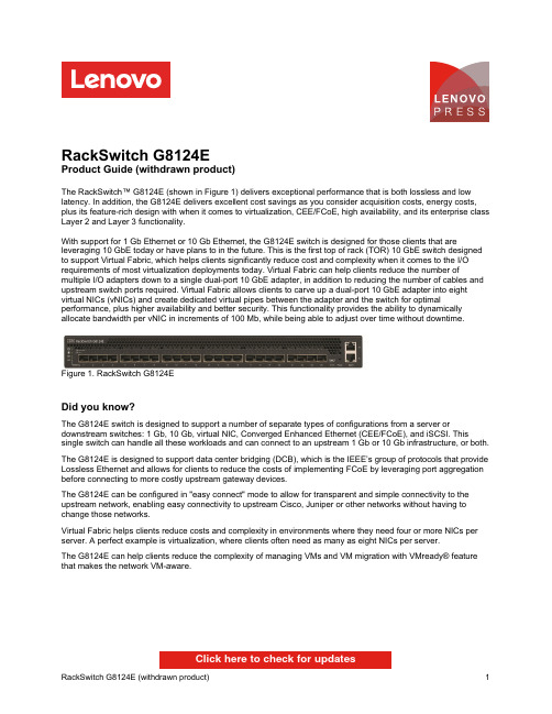
RackSwitch G8124EProduct Guide (withdrawn product)The RackSwitch™ G8124E (shown in Figure 1) delivers exceptional performance that is both lossless and low latency. In addition, the G8124E delivers excellent cost savings as you consider acquisition costs, energy costs, plus its feature-rich design with when it comes to virtualization, CEE/FCoE, high availability, and its enterprise class Layer 2 and Layer 3 functionality.With support for 1 Gb Ethernet or 10 Gb Ethernet, the G8124E switch is designed for those clients that are leveraging 10 GbE today or have plans to in the future. This is the first top of rack (TOR) 10 GbE switch designed to support Virtual Fabric, which helps clients significantly reduce cost and complexity when it comes to the I/O requirements of most virtualization deployments today. Virtual Fabric can help clients reduce the number of multiple I/O adapters down to a single dual-port 10 GbE adapter, in addition to reducing the number of cables and upstream switch ports required. Virtual Fabric allows clients to carve up a dual-port 10 GbE adapter into eight virtual NICs (vNICs) and create dedicated virtual pipes between the adapter and the switch for optimal performance, plus higher availability and better security. This functionality provides the ability to dynamically allocate bandwidth per vNIC in increments of 100 Mb, while being able to adjust over time without downtime.Figure 1. RackSwitch G8124EDid you know?The G8124E switch is designed to support a number of separate types of configurations from a server or downstream switches: 1 Gb, 10 Gb, virtual NIC, Converged Enhanced Ethernet (CEE/FCoE), and iSCSI. This single switch can handle all these workloads and can connect to an upstream 1 Gb or 10 Gb infrastructure, or both. The G8124E is designed to support data center bridging (DCB), which is the IEEE’s group of protocols that provide Lossless Ethernet and allows for clients to reduce the costs of implementing FCoE by leveraging port aggregation before connecting to more costly upstream gateway devices.The G8124E can be configured in "easy connect" mode to allow for transparent and simple connectivity to the upstream network, enabling easy connectivity to upstream Cisco, Juniper or other networks without having to change those networks.Virtual Fabric helps clients reduce costs and complexity in environments where they need four or more NICs per server. A perfect example is virtualization, where clients often need as many as eight NICs per server.The G8124E can help clients reduce the complexity of managing VMs and VM migration with VMready® feature that makes the network VM-aware.Click here to check for updatesover OM3 multimode fiber or up to 400 meters over OM4 multimode fiber with LC connectors. The 10GBASE-LR transceivers can support distances up to 10 kilometers on single mode fiber with LC connectors. For extended distances, the 10GBASE-ER transceivers can support distances up to 40 kilometers on single mode fiber with LC connectors.Table 3 lists the supported cables and transceivers.Table 3. Supported transceivers and direct-attach cablesDescription Partnumber Feature code(MTM 7309-HC6 / 7309-HC7)MaximumquantitysupportedSFP transceivers - 1 GbELenovo 1000BASE-T SFP Transceiver (does not support 10/100 Mbps)00FE333A5DL24 Lenovo 1000BASE-SX SFP Transceiver81Y1622326924 Lenovo 1000BASE-LX SFP Transceiver90Y9424A1PN24 SFP+ transceivers - 10 GbELenovo 10GBASE-SR SFP+ Transceiver46C3447505324 Lenovo 10GBASE-LR SFP+ Transceiver90Y9412A1PM24 Lenovo 10GBASE-ER SFP+ Transceiver90Y9415A1PP24 Optical cables for 1 GbE SFP SX and 10 GbE SFP+ SR transceiversLenovo 0.5m LC-LC OM3 MMF Cable00MN499ASR524 Lenovo 1m LC-LC OM3 MMF Cable00MN502ASR624 Lenovo 3m LC-LC OM3 MMF Cable00MN505ASR724 Lenovo 5m LC-LC OM3 MMF Cable00MN508ASR824 Lenovo 10m LC-LC OM3 MMF Cable00MN511ASR924 Lenovo 15m LC-LC OM3 MMF Cable00MN514ASRA24 Lenovo 25m LC-LC OM3 MMF Cable00MN517ASRB24 Lenovo 30m LC-LC OM3 MMF Cable00MN520ASRC24SFP+ passive direct-attach cables - 10 GbELenovo 0.5m Passive DAC SFP+ Cable00D6288A3RG24 Lenovo 1m Passive DAC SFP+ Cable90Y9427A1PH24 Lenovo 1.5m Passive DAC SFP+ Cable00AY764A51N24 Lenovo 2m Passive DAC SFP+ Cable00AY765A51P24 Lenovo 3m Passive DAC SFP+ Cable90Y9430A1PJ24 Lenovo 5m Passive DAC SFP+ Cable90Y9433A1PK24 Lenovo 7m Passive DAC SFP+ Cable00D6151A3RH24 SFP+ active direct-attach cables - 10 GbELenovo 1m Active DAC SFP+ Cable95Y0323A25A24 Lenovo 3m Active DAC SFP+ Cable95Y0326A25B24 Lenovo 5m Active DAC SFP+ Cable95Y0329A25C24 Lenovo 1m Active DAC SFP+ Cable (replaces 95Y0323)00VX111AT2R24 Lenovo 3m Active DAC SFP+ Cable (replaces 95Y0326)00VX114AT2S24 Lenovo 5m Active DAC SFP+ Cable (replaces 95Y0329)00VX117AT2T24Figure 2. Front panel of the RackSwitch G8124E Figure 3. Rear panel of the RackSwitch G8124ENetwork cabling requirementsThe network cables that can be used with the switch are listed in Table 4.Table 4. G8124E network cabling requirementsTransceiver Standard Cable Connector 10 Gb Ethernet10GBASE-SR SFP+ Transceiver (46C3447)10GBASE-SR Up to 30 m with fiber optic cables supplied by Lenovo (seeTable 3); 850 nm OM3 multimode fiber cable up to 300 m orup to 400 m with OM4 multimode fiberLC10GBASE-LR SFP+Transceiver (90Y9412)10GBASE-LR1310 nm single-mode fiber cable up to 10 km LC10GBASE-ER SFP+Transceiver (90Y9415)10GBASE-ER1310 nm single-mode fiber cable up to 40 km LC Direct attach cable10GSFP+Cu SFP+ DAC cables up to 7 m (see Table 3)SFP+ 1 Gb Ethernet1000BASE-T SFPTransceiver (00FE333)1000BASE-T UTP Category 5, 5E, and 6 up to 100 meters RJ-451000BASE-SX SFP Transceiver (81Y1622)1000BASE-SX Up to 30 m with fiber optic cables supplied by Lenovo (seeTable 3); 850 nm multimode fiber cable up to 550 m (50 µ)or up to 220 m (62.5 µ)LC1000BASE-LX SFPTransceiver (90Y9424)1000BASE-LX1310 nm single-mode fiber cable up to 10 km LC Management ports1 GbE management ports1000BASE-T UTP Category 5, 5E, and 6 up to 100 meters RJ-45 RS-232 management port RS-232DB-9-to-mini-USB or RJ-45-to-mini-USB console cable(comes standard with the switch)Mini-USB WarrantyFigure 4. Virtual Fabric topologyFigure 5. G8124E top-of-rack switchFigure 6. Rack-optimized server aggregation: 1 GbE attached rack serversFigure 7. G8124E benefits for IP storage over 10 GbE Related publications and linksTrademarksLenovo and the Lenovo logo are trademarks or registered trademarks of Lenovo in the United States, other countries, or both. A current list of Lenovo trademarks is available on the Web athttps:///us/en/legal/copytrade/.The following terms are trademarks of Lenovo in the United States, other countries, or both:Lenovo®BladeCenter®Flex SystemIntelligent ClusterLenovo ServicesNMotion®NeXtScaleNeXtScale System®RackSwitchSystem x®ThinkServer®VMready®iDataPlex®The following terms are trademarks of other companies:Hyper-V® and Microsoft® are trademarks of Microsoft Corporation in the United States, other countries, or both. Other company, product, or service names may be trademarks or service marks of others.。
昂达光电耦合器OP23443产品说明书

Dimensions: [mm]1221Scale - 3:1Würth Elektronik eiSos GmbH & Co. KG EMC & Inductive Solutions Max-Eyth-Str. 174638 Waldenburg Germany140814240010Würth Elektronik eiSos GmbH & Co. KGEMC & Inductive Solutions140814240010 Max-Eyth-Str. 174638 WaldenburgGermanyWürth Elektronik eiSos GmbH & Co. KGEMC & Inductive Solutions140814240010 Max-Eyth-Str. 174638 WaldenburgGermanyWürth Elektronik eiSos GmbH & Co. KGEMC & Inductive Solutions140814240010 Max-Eyth-Str. 174638 WaldenburgGermanyWürth Elektronik eiSos GmbH & Co. KGEMC & Inductive Solutions140814240010 Max-Eyth-Str. 174638 WaldenburgGermanyWürth Elektronik eiSos GmbH & Co. KGEMC & Inductive Solutions140814240010 Max-Eyth-Str. 174638 WaldenburgGermanyWürth Elektronik eiSos GmbH & Co. KGEMC & Inductive Solutions140814240010 Max-Eyth-Str. 174638 WaldenburgGermanyWürth Elektronik eiSos GmbH & Co. KGEMC & Inductive Solutions140814240010 Max-Eyth-Str. 174638 WaldenburgGermanyWürth Elektronik eiSos GmbH & Co. KGEMC & Inductive Solutions140814240010 Max-Eyth-Str. 174638 WaldenburgGermanyT e m p e r a t u r eT T T Würth Elektronik eiSos GmbH & Co. KG EMC & Inductive Solutions Max-Eyth-Str. 174638 Waldenburg Germany140814240010Cautions and Warnings:The following conditions apply to all goods within the product series of Optoelectronic Components of Würth Elektronik eiSos GmbH & Co. KG:General:•This optoelectronic component is designed and manufactured for use in general electronic equipment.•Würth Elektronik must be asked for written approval (following the PPAP procedure) before incorporating the components into any equipment in fields such as military, aerospace, aviation, nuclear control, submarine, transportation (automotive control, train control,ship control), transportation signal, disaster prevention, medical, public information network, etc. where higher safety and reliability are especially required and/or if there is the possibility of direct damage or human injury.•Optoelectronic components that will be used in safety-critical or high-reliability applications, should be pre-evaluated by the customer. •The optoelectronic component is designed and manufactured to be used within the datasheet specified values. If the usage and operation conditions specified in the datasheet are not met, the wire insulation may be damaged or dissolved. •Do not drop or impact the components, the component may be damaged•Würth Elektronik products are qualified according to international standards, which are listed in each product reliability report. Würth Elektronik does not warrant any customer qualified product characteristics beyond Würth Elektroniks’ specifications, for its validity and sustainability over time.•The responsibility for the applicability of the customer specific products and use in a particular customer design is always within the authority of the customer. All technical specifications for standard products also apply to customer specific products.•Unless Würth Elektroik has given its express consent, the customer is under no circumstances entitled to reverse engineer, disassemble or otherwise attempt to extract knowledge or design information from the optoelectronic component.Product specific:Soldering:•The solder profile must comply with the technical product specifications. All other profiles will void the warranty. •All other soldering methods are at the customers’ own risk•The soldering pad pattern shown above is a general recommendation for the easy assembly of optoelectronic components. If a high degree of precision is required for the selected application (i.e. high density assembly), the customer must ensure that the soldering pad pattern is optimized accordingly.Cleaning and Washing:•Washing agents used during the production to clean the customer application might damage or change the characteristics of the optoelectronic component body, marking or plating. Washing agents may have a negative effect on the long-term functionality of the product.• Using a brush during the cleaning process may break the optoelectronic component body. Therefore, we do not recommend using a brush during the PCB cleaning process.Potting:•If the product is potted in the customer application, the potting material might shrink or expand during and after hardening. Shrinking could lead to an incomplete seal, allowing contaminants into the optoelectronic component body, pins or termination. Expansion could damage the components. We recommend a manual inspection after potting to avoid these effects.Storage Conditions:• A storage of Würth Elektronik products for longer than 12 months is not recommended. Within other effects, the terminals may suffer degradation, resulting in bad solderability. Therefore, all products shall be used within the period of 12 months based on the day of shipment.•Do not expose the optoelectronic component to direct sunlight.•The storage conditions in the original packaging are defined according to DIN EN 61760-2.•For a moisture sensitive component, the storage condition in the original packaging is defined according to IPC/JEDEC-J-STD-033. It is also recommended to return the optoelectronic component to the original moisture proof bag and reseal the moisture proof bag again. •The storage conditions stated in the original packaging apply to the storage time and not to the transportation time of the components.Packaging:•The packaging specifications apply only to purchase orders comprising whole packaging units. If the ordered quantity exceeds or is lower than the specified packaging unit, packaging in accordance with the packaging specifications cannot be ensured.Handling:•Violation of the technical product specifications such as exceeding the nominal rated current, will void the warranty. •The product design may influence the automatic optical inspection.•Certain optoelectronic component surfaces consist of soft material. Pressure on the top surface has to be handled carefully to prevent negative influence to the function and reliability of the optoelectronic components.•ESD prevention methods need to be applied for manual handling and processing by machinery. •Resistors for protection are obligatory.•In addition to optoelectronic components testing, products incorporating these devices have to comply with the safety precautions given in IEC 60825-1, IEC 62471 and IEC 62778.Technical specification:•The typical and/or calculated values and graphics of technical parameters can only reflect statistical figures. The actual parameters ofeach single product, may differ from the typical and/or calculated values or the typical characteristic line.Würth Elektronik eiSos GmbH & Co. KG EMC & Inductive Solutions Max-Eyth-Str. 174638 Waldenburg GermanyCHECKED REVISION DATE (YYYY-MM-DD)GENERAL TOLERANCEPROJECTION METHODSaVo001.0042023-08-22DIN ISO 2768-1mDESCRIPTIONWL-OCPT Optocoupler PhototransistorORDER CODE140814240010SIZE/TYPEBUSINESS UNITSTATUSPAGE•In the characteristics curves, all values given in dotted lines may show a higher deviation than the paramters mentioned above. •On each reel, only one bin is sorted and taped. The bin is defined on the current transfer ratio.•In order to ensure highest availability, the reel binning of standard deliveries can vary. A single bin cannot be ordered. Please contact us in advance, if you need a particular bin sorting before placing your order.•These cautions and warnings comply with the state of the scientific and technical knowledge and are believed to be accurate and reliable. However, no responsibility is assumed for inaccuracies or incompleteness.The customer has the sole responsibility to ensure that he uses the latest version of this datasheet, which is available on Würth Elektronik’s homepage. Unless otherwise agreed in writing (i.e. customer specific specification), changes to the content of this datasheet may occurwithout notice, provided that the changes do not have a significant effect on the usability of the optoelectronic components.Würth Elektronik eiSos GmbH & Co. KG EMC & Inductive Solutions Max-Eyth-Str. 174638 Waldenburg GermanyCHECKED REVISION DATE (YYYY-MM-DD)GENERAL TOLERANCEPROJECTION METHODSaVo001.0042023-08-22DIN ISO 2768-1mDESCRIPTIONWL-OCPT Optocoupler PhototransistorORDER CODE140814240010SIZE/TYPEBUSINESS UNITSTATUSPAGEImportant NotesThe following conditions apply to all goods within the product range of Würth Elektronik eiSos GmbH & Co. KG:1. General Customer ResponsibilitySome goods within the product range of Würth Elektronik eiSos GmbH & Co. KG contain statements regarding general suitability for certain application areas. These statements about suitability are based on our knowledge and experience of typical requirements concerning the areas, serve as general guidance and cannot be estimated as binding statements about the suitability for a customer application. The responsibility for the applicability and use in a particular customer design is always solely within the authority of the customer. Due to this fact it is up to the customer to evaluate, where appropriate to investigate and decide whether the device with the specific product characteristics described in the product specification is valid and suitable for the respective customer application or not.2. Customer Responsibility related to Specific, in particular Safety-Relevant ApplicationsIt has to be clearly pointed out that the possibility of a malfunction of electronic components or failure before the end of the usual lifetime cannot be completely eliminated in the current state of the art, even if the products are operated within the range of the specifications.In certain customer applications requiring a very high level of safety and especially in customer applications in which the malfunction or failure of an electronic component could endanger human life or health it must be ensured by most advanced technological aid of suitable design of the customer application that no injury or damage is caused to third parties in the event of malfunction or failure of an electronic component. Therefore, customer is cautioned to verify that data sheets are current before placing orders. The current data sheets can be downloaded at .3. Best Care and AttentionAny product-specific notes, cautions and warnings must be strictly observed. Any disregard will result in the loss of warranty.4. Customer Support for Product SpecificationsSome products within the product range may contain substances which are subject to restrictions in certain jurisdictions in order to serve specific technical requirements. Necessary information is available on request. In this case the field sales engineer or the internal sales person in charge should be contacted who will be happy to support in this matter.5. Product R&DDue to constant product improvement product specifications may change from time to time. As a standard reporting procedure of the Product Change Notification (PCN) according to the JEDEC-Standard inform about minor and major changes. In case of further queries regarding the PCN, the field sales engineer or the internal sales person in charge should be contacted. The basic responsibility of the customer as per Section 1 and 2 remains unaffected.6. Product Life CycleDue to technical progress and economical evaluation we also reserve the right to discontinue production and delivery of products. As a standard reporting procedure of the Product Termination Notification (PTN) according to the JEDEC-Standard we will inform at an early stage about inevitable product discontinuance. According to this we cannot guarantee that all products within our product range will always be available. Therefore it needs to be verified with the field sales engineer or the internal sales person in charge about the current product availability expectancy before or when the product for application design-in disposal is considered. The approach named above does not apply in the case of individual agreements deviating from the foregoing for customer-specific products.7. Property RightsAll the rights for contractual products produced by Würth Elektronik eiSos GmbH & Co. KG on the basis of ideas, development contracts as well as models or templates that are subject to copyright, patent or commercial protection supplied to the customer will remain with Würth Elektronik eiSos GmbH & Co. KG. Würth Elektronik eiSos GmbH & Co. KG does not warrant or represent that any license, either expressed or implied, is granted under any patent right, copyright, mask work right, or other intellectual property right relating to any combination, application, or process in which Würth Elektronik eiSos GmbH & Co. KG components or services are used.8. General Terms and ConditionsUnless otherwise agreed in individual contracts, all orders are subject to the current version of the “General Terms and Conditions of Würth Elektronik eiSos Group”, last version available at .Würth Elektronik eiSos GmbH & Co. KGEMC & Inductive SolutionsMax-Eyth-Str. 174638 WaldenburgGermanyCHECKED REVISION DATE (YYYY-MM-DD)GENERAL TOLERANCE PROJECTIONMETHODSaVo001.0042023-08-22DIN ISO 2768-1mDESCRIPTIONWL-OCPT OptocouplerPhototransistor ORDER CODE140814240010SIZE/TYPE BUSINESS UNIT STATUS PAGE。
(优选)三相异步电动机铭牌相关参数介绍详解.

1.电机的产品型号:
1234
补充代号 特殊环境代号 规格代号 产品代号 电机型号一般由产品代号、规格代号、特殊环境 代号、补充代号等四部分组成,并按以上顺序排 列。
低压电机铭牌
高压电机铭牌
1.1 常用异步电动机的产品代号:
序号 1 2 3 4 5 6 7 8 9 10 11 12
代号 G H W F T TH TA
1.4 补充代号:用汉语拼音字母或是阿拉伯数字表示。
• 2、产品型号示例
2.1 Y KS L 1800-12/1730 -1
电机底座与泵直接连接
定子铁芯外径 极数 额定功率 立式 空-水冷却器 鼠笼转子三相立式异步电动机
备注:一期循环水泵电机,立式电机指功率,卧式电机指中心高
middle),L表示长机座(long)。铁心长度按由短至长顺序 用数字1、2、3表示。
序
系列产品
号
1 小型异步电动机
规格代号
中心高(mm)-机座长度(字母代号)-铁心长度 (数 字代号)-极数
2 中大型异步电动机 中心高(mm)-铁心长度(数字代号)- 极数
1.3 特殊环境代号
环境名称 “高”原用 “船”(海)用 户“外”用 化工防“腐”用 “热”带用 “湿热”带用 “干热”带用
和先后顺序。
5. 防护型式 IPXX (GB/T 4208 外壳防护分级(IP代码) 防护标志由字母IP和两个表示防护等级的表征数字组成。
第一位数字表示:防止人体触及或接近壳内带电部分和触及壳内 转动部件(光滑的旋转轴和类似部件除外),以及防止固体异物进入电机
(表示防尘等级)。 第二位数字表示:防止由于电机进水而引起的有害影响(表示防水等 级)。 对特殊应用和适用于规定气候条件的电机,其外壳防护等级的表
IN4148中文资料
DIA.
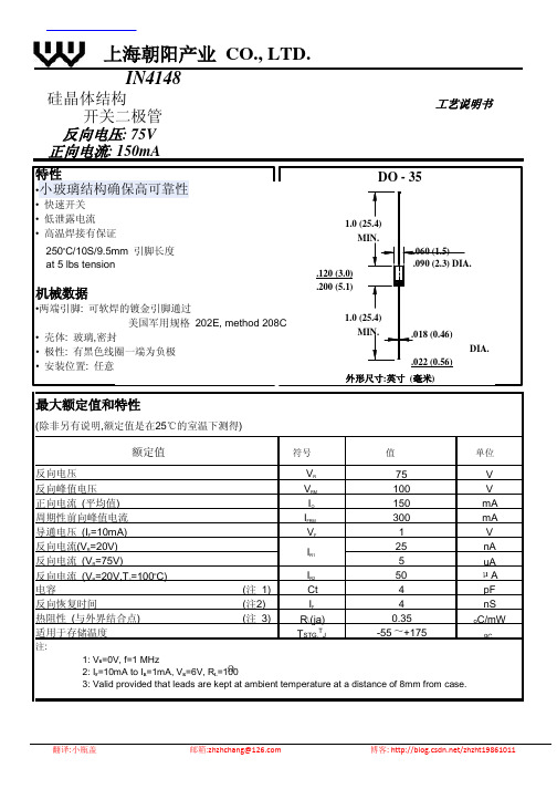
最大额定值和特性
(除非另有说明,额定值是在25℃的室温下测得)
额Байду номын сангаас值
符号
值
单位
反向电压
VR
75
V
反向峰值电压 正向电流 (平均值)
VRM
100
V
IO
150
mA
周期性前向峰值电流
IFRM
300
mA
导通电压 (IF=10mA)
VF
1
V
反向电流(VR=20V) 反向电流 (VR=75V)
IR1
25
022056最大额定值和特性除非另有说明额定值是在25的室温下测得反向电压额定值符号vr75单位反向峰值电压正向电流平均值周期性前向峰值电流导通电压if10ma反向电流vr20v反向电流vr75v反向电流vr20vtj100vrmioifrmvfir1ir2100150300mamanaua电容反向恢复时间035pfnsocmw适用于存储温度ir1mavr6vrl100tstg55175validprovidedambienttemperature8mmfromcase
nA
5
uA
反向电流 (VR=20V,TJ=100oC)
IR2
50
A
电容
(注 1)
Ct
4
pF
反向恢复时间
(注2)
IF
4
nS
热阻性 (与外界结合点) 适用于存储温度
注:
(注 3)
R(ja) TSTG,TJ
0.35 -55 +175
oC/mW
oC
1: VR=0V, f=1 MHz 2: IF=10mA to IR=1mA, VR=6V, RL=100 3: Valid provided that leads are kept at ambient temperature at a distance of 8mm from case.
4812说明书
简介谢谢您购买绿扬牌YB4812型晶体管特性图示仪。
为保证正确利用,请在利用前认真阅读此说明书.阅毕,请将说明书保留好。
该图示仪依照严格的质量操纵标准生产,元器件进行了全面的挑选老化。
售后效劳:若是显现任何故障,请与咱们的销售部或各维修点联系,以取得快捷而有效的售后效劳。
注意:该仪器必需在规定的工作环境中利用,才能保证其处于最正确工作状态。
警示:电源插头应有接地爱惜,改换保险丝时应断开输入电源。
非专业技术人员请勿打开盖板。
1.概述YB4812型晶体管特性图示仪是一种用于测量各类半导体管特性曲线和静态参数的测量仪器。
本仪器是新一代便携式图示仪,整机采纳新颖电路设计技术,除具有一般图示仪的功能外,还具有外形轻巧、操作简便、性能稳固靠得住、性价比高的特点,能知足大部份半导体器件的测试要求。
适合于工厂生产线、大专院校、仪器修理业等领域。
2.要紧技术指标Y轴系统集电极电流范围(Ic):10μA/div~div,分14档,误差不超过±5%。
扩展×10,误差不超过±10%。
X轴系统集电极电压范围(Vc):div~50V/div,分10档,误差不超过±5%。
基极电压范围(Vbe):~div,分4档,误差不超过±5%。
阶梯信号阶梯电流范围:5μA/div~10mA/div,分11档,误差不超过±5%。
阶梯电压范围:~,分4档,误差不超过±5%。
每簇级数:0~10级持续可调。
串联电阻:0、10kΩ,误差不超过±10%。
集电极扫描电源峰值电压:0~50V、0~500V持续可调。
电流容量:0~50V 2A;0~500V 500mA。
功耗限制电阻:约0~100kΩ持续可调。
容性电流:500V时小于5μA。
其他示波管:15SJ118Y-14(内)。
外型尺寸:430mm×320mm×150mm (D×B×H)。
常用稳压管型号

常用稳压型号参数查询DZ是稳压管的电器编号,1N4148就是一个0.6V的稳压管,下面是稳压管上的编号对应的稳压值,有些小的稳压管也会在管体上直接标稳压电压,如5V6就是5.6V的稳压管;美标稳压二极管型号:HITACHI日立:HITACHI日立0.5W稳压二极管型号参数稳压HZ3A1 2.5~2.7VHZ3A2 2.6~2.8VHZ3A3 2.6~2.9VHZ3B1 2.8~3.0VHZ3B2 2.9~3.1VHZ3B3 3.0~3.2V线性稳压器件输入输出电流相等,压降3V以上型号稳压V 最大输出电流可替代型号79L05 -5V 100mA79L06 -6V 100mA79L08 -8V 100mALM7805 5V 1A L7805,LM340T5 LM7806 6V 1A L7806LM7808 8V 1A L7808LM7809 9V 1A L7809LM7812 12V 1A L7812,LM340T12 LM7815 15V 1A L7815,LM340T15 LM7818 18V 1A L7815LM7824 24V 1A L7824LM7905 -5V 1A L7905LM7906 -6V 1A L7906,KA7906 LM7908 -8V 1A L7908LM7909 -9V 1A L7909LM7912 -12V 1A L7912LM7915 -15V 1A L7915LM7918 -18V 1A L7918LM7924 -24V 1A L792478L05 5V 100mA78L06 6V 100mA78L08 8V 100ma78L09 9V 100ma78L12 12V 100ma78L15 15V 100ma78L18 18V 100ma78L24 24V 100ma开关稳压器件电压转换效率高型号说明最大输出电流LM1575T-3.3 3.3V简易开关电源稳压器 1ALM1575T-5.0 5V简易开关电源稳压器 1A LM1575T-12 12V简易开关电源稳压器 1A LM1575T-15 15V简易开关电源稳压器 1A LM1575T-ADJ 简易开关电源稳压器可调1.23V~37V 1ALM1575HVT-3.3 3.3V简易开关电源稳压器 1A LM1575HVT-5.0 5V简易开关电源稳压器 1A LM1575HVT-12 12V简易开关电源稳压器 1ALM1575HVT-15 15V简易开关电源稳压器 1ALM1575HVT-ADJ 简易开关电源稳压器可调1.23V~37V 1ALM2575T-3.3 3.3V简易开关电源稳压器 1A LM2575T-5.0 5V简易开关电源稳压器 1A LM2575T-12 12V简易开关电源稳压器 1A LM2575T-15 15V简易开关电源稳压器 1A LM2575T-ADJ 简易开关电源稳压器可调1.23V~ 37V 1ALM2575HVT-3.3 3.3V简易开关电源稳压器 1A LM2575HVT-5.0 5V简易开关电源稳压器 1A LM2575HVT-12 12V简易开关电源稳压器 1A LM2575HVT-15 15V简易开关电源稳压器 1A LM2575HVT-ADJ 简易开关电源稳压器可调1.23V~37V 1ALM2576T-3.3 3.3V简易开关电源稳压器 3A LM2576T-5.0 5.0V简易开关电源稳压器 3A LM2576T-12 12V简易开关电源稳压器 3A LM2576T-15 15V简易开关电源稳压器 3A LM2576T-ADJ 简易开关电源稳压器可调1.23V~37V 3ALM2576HVT-3.3 3.3V简易开关电源稳压器 3A LM2576HVT-5.0 5.0V简易开关电源稳压器 3ALM2576HVT-12 12V简易开关电源稳压器 3ALM2576HVT-15 15V简易开关电源稳压器 3ALM2576HVT-ADJ 简易开关电源稳压器可调1.23V~37V 3A。
电磁保护设备TeSys GV系列产品参数表说明书
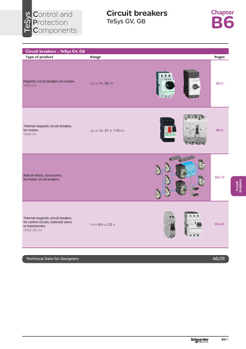
C i r c u i t b r e a k e r sCircuit breakersTeSys GV, GBC ontrol and P rotection C omponentsChapterB60.75g g 1.1g g 1.5375 2.533.5 LR2 K0308GV2LE071.1g g –––––– 2.533.5 LR2 K0308GV2LE071.5g g 1.5g g 3375451 LR2 K0310GV2LE08––– 2.2g g –––451 LR2 K0312GV2LE082.2g g 3501004375 6.378 LR2 K0312GV2LE103g g 410100 5.537510138 LR2 K0314GV2LE144g g 5.510100–––10138 LR2 K0316GV2LE14––––––7.537510138 LRD 14GV2LE14––––––937514170 LRD 16GV2LE165.515507.56751137514170 LR2 K0321GV2LE167.5155096751537518223 LRD 21GV2LE20915401147518.537525327 LRD 22GV2LE2211154015475–––25327 LRD 22GV2LE2215105018.54752237532416LRD 32GV2LE32(1) As % of Icu.g ) > 100 kA.GV2 LE10D F 526144.t i fC i r c u i t b r e a k e r s0.09––––––0.45LRD 03GV2L030.12g g –––0.37g g 0.638LRD 04GV2L040.18g g ––––––0.638LRD 04GV2L04––––––0.55g g 113LRD 05GV2L050.25g g ––––––113LRD 05GV2L05––––––0.75g g 113LRD 06GV2L050.37g g 0.37g g –––113LRD 05GV2L050.55g g 0.55g g 1.1g g 1.622.5LRD 06GV2L06–––0.75g g ––– 1.622.5LRD 06GV2L060.75g g 1.1g g 1.54100 2.533.5LRD 07GV2L07Example: GV3 L32 becomes GV3 L326.(1) As % of Icu. Associated current limiter or fuses, where required. See characteristics page B6/33.g > 100 kA.GV2 L10D F 526145.t i fGV3 L65D F 526146.t i fTeSys GVThermal-magnetic motor circuit breakers GV2 ME0.06gg––––––0.16…0.252.4GV2ME020.09g g––––––0.25…0.405GV2ME030.12 0.18g g g g – –– –– – 0.37 –g–g –0.40…0.638GV2ME040.25gg––– 0.55gg0.63…113GV2ME050.37 0.55 –g g –g g –0.37 0.55 0.75g g g g g g – 0.75 1.1– g g – g g 1…1622.5GV2ME060.75g g1.1gg1.5375 1.6...2.533.5GV2ME071.1 1.5g g g g 1.5 2.2g g g g 2.2 3 3 375 75 2.5 (4)51GV2ME082.2gg350100 43754...6.378GV2ME103 4g g g g 4 5.510 10100 100 5.5 7.5 3 375 756 (10)138GV2ME145.5 –15 –50 –7.5 – 6 –75 – 9 11 3 375 759…14170GV2ME167.5155096751537513…18223GV2ME209154011475 18.537517…23327GV2ME2111154015475 –––20…25327GV2ME22 (3)15105018.54752237524 (32)416GV2ME32Motor circuit breakers from 0.06 to 15 kW / 400 V, with lugsTo order thermal magnetic circuit breakers with connection by lugs, add the digit 6 to the end of reference selected above.Example: GV2 ME08 becomes GV2 ME086.Thermal magnetic circuit breakers GV2 ME with built-in auxiliary contact block With instantaneous auxiliary contact block (composition, see page B6/11):b GV AE1, add suffix AE1TQ to the motor circuit breaker reference selected above. Example: GV2 ME01AE1TQ .b GV AE11, add suffix AE11TQ to the motor circuit breaker reference selected above. Example: GV2 ME01AE11TQ .b GV AN11, add suffix AN11TQ to the motor circuit breaker reference selected above. Example: GV2 ME01AN11TQ .These circuit breakers with built-in contact block are sold in lots of 20 units in a single pack.(1) As % of Icu.(2) The thermal trip setting must be within the range marked on the graduated knob.(3) Maximum rating which can be mounted in enclosures GV2 MC or MP , please consult your Regional Sales Office. g > 100 kA.GV2 ME10D F 526134.t i fC i r c u i t b r e a k e r sTeSys GVTeSys protection componentsThermal-magnetic motor circuit breakers GV2 MEReferences0.06g g ––– 0.16…0.25 2.4GV2ME0230.09g g ––– 0.25…0.405GV2ME0330.120.18g g g g –––0.40…0.638GV2ME0430.250.37g g g g 0.37g g 0.63…113GV2ME0530.370.55g g g g 0.370.550.75g g g g g g 1…1.622.5GV2ME0630.75g g1.1g g 1.6…2.533.5GV2ME0731.11.5g g g g 1.52.2g g g g 2.5…451GV2ME0832.2g g 350100 4…6.378GV2ME10334g g g g 45.510101001006…10138GV2ME1435.515507.5675 9…14170GV2ME1637.515509675 13…18223GV2ME203911151540401147517…23327GV2ME2131115401547520 (25)327GV2ME223Contact blocksDescription Mounting Maximum number Type of contacts Sold in lots of Unitreference Instantaneous auxiliary contactsFront 1N/O + N/C 10GVAE113N/O + N/O 10GVAE203LH side2N/O + N/C 1GVAN113N/O + N/O1GVAN203AccessoryDescriptionApplicationSold in lots of Unitreference Cable end reducerFor connection of conductors from 1 to 1.5 mm 220LA9D99(1) For connection of conductors from 1 to 1.5 mm 2, the use of an LA9 D99 cable end reducer is recommended.(2) Maximum rating which can be mounted in enclosures GV2 MC or MP , please consult your Regional Sales Office (3) The thermal trip setting must be within the range marked on the graduated knob.g > 100 kA.GV2 ME pp 3D F 526135.t i fLA9 D99D F 533898.e p sTeSys GVReferencesTeSys protection componentsThermal-magnetic motor circuit breakersGV2 P, GV3 P and GV3 ME80GV2 P10D F 526137.t i fGV3 P65D F 526139.t i fGV3 P651D F 526140.t i fC i r c u i t b r e a k e r sTeSys GVReferences93610011181001581007.59707010010091150501001001115101010010012…20GV7RS20 2.0109113636100100111518181001001518.58810010015…25GV7RE25 2.0109117070100100111550501001001518.5101010010015…25GV7RS25 2.01018.53610018.522181810010022810025…40GV7RE40 2.01018.57010018.550100221010025…40GV7RS40 2.0102236100301810030810030…50GV7RE50 2.01522701003050100301010030 (50)GV7RS502.01537361004555181810010055810048...80GV7RE80 2.040377010045555050100100551010048...80GV7RS80 2.0404536100–1810075810060...100GV7RE100 2.0404570100–50100751010060...100GV7RS100 2.0405575353510010075903030100100901108810010090 (150)GV7RE1502.020557570701001007590505010010090110101010010090…150GV7RS150 2.02090110353510010011013216030303010010010016020088100100132…220GV7RE220 2.3509011070701001001101321605050501001001001602001010100100132…220GV7RS220 2.350(1) As % of lcu.TeSys protection componentsThermal-magnetic motor circuit breakers GV7 RGV7 RE40D F 526138.t i fGV7 RS220D F 526141.t i f0.12–0.120.180.18–0.370.40…0.6313GV2RT040.090.120.250.370.250.370.370.550.63…122GV2RT050.180.250.370.550.370.550.370.550.750.751.11…1.633GV2RT060.370.750.751.1 1.11.51.6…2.551GV2RT070.550.75 1.11.5 1.51.52.2 2.23 2.5…478GV2RT081.12.22.23344…6.3138GV2RT101.52.234445.5 5.57.56…10200GV2RT142.23 5.55.57.57.59119…14280GV2RT1647.57.5991513…18400GV2RT205.5911111118.517…23400GV2RT21(1) The thermal trip setting must be within the range marked on the graduated knob.GV2 RTD F 526142.t i fC i r c u i t b r e a k e r sblack handle, blue legend plate(1) The thermal trip setting must be within the range marked on the graduated knob.(2) Other accessories such as mounting, cabling and marking accessories are identical to those used for GV2 ME motor circuit breakers, see page B6/13.GV2 RTD F 526142.t i fD F 526340.e p sC i r c u i t b r e a k e r sTeSys GVDescription Mounting Maximum number Type of contacts Sold inlots of Unitreference Instantaneous auxiliary contactsFront (1)1N/O or N/C (2)10GVAE1N/O + N/C 10GVAE11N/O + N/O10GVAE20Side (LH)2N/O + N/C1GVAN11N/O + N/O1GVAN20Fault signalling contact + instantaneous auxiliary contact Side (3) (LH)1N/O (fault)+ N/O1GVAD1010+ N/C1GVAD1001N/C (fault)+ N/O1GVAD0110+ N/C1GVAD0101Short-circuit signalling contactSide (LH)1C/O common point1GVAM11(1 block on RH sideof circuit breaker GV2 ME)50 Hz GVAX11560 Hz GVAX116127 V60 Hz GVAX115220…240 V 50 Hz GVAX22560 Hz GVAX226380…400 V50 Hz GVAX38560 Hz GVAX386415…440 V 50 Hz GVAX415440 V60 Hz GVAX385Add-on contact blocksDescriptionMountingMaximum number Reference Visible isolation block (5)Front (1)1GV2AK00 (6)LimitersAt top(GV2 ME and GV2 P)1GV1L3Independent1LA9LB920(1) Mounting of a GV AE contact block or a GV2 AK00 visible isolation block on GV2 P and GV2 L .(2) Choice of N/C or N/O contact operation, depending on which way round the reversible block is mounted.(3) The GV AD is always mounted next to the circuit breaker.(4) To order an undervoltage trip: replace the dot (p ) in the reference with a U , example: GV AU025. To order a shunt trip: replace the dot (p ) in the reference with an S , example: GV AS025.(5) Visible isolation of the 3 poles upstream of circuit breaker GV2 P and GV2 L .Visible isolation block GV2 AK00 cannot be used with motor circuit breakers GV2 P32 and GV2 L32 (Ith max = 25 A).(6) Ie Max = 32 A.ReferencesTeSys protection componentsThermal-magnetic and magnetic motor circuit breakers GV2 with screw clamp connectionsAdd-on blocks and accessoriesCharacteristics:pages B6/89 and B6/94Dimensions, schemes:pages B6/70 to B6/82LA9LB920D B 126629.e p sC i r c u i t b r e a k e r sTeSys GVTerminal blockfor supply to one or more GV2 G busbar setsConnection from the top1GV1G09Can be fitted with current limiter GV1 L3 (GV2 ME and GV2 P)1GV2G05Cover for terminal block For mounting in modular panels10LA9E07Flexible 3-pole connection for connecting a GV2 to a contactor LC1-D09…D25 Centre distance between mounting rails: 100…120 mm10GV1G02Set of connections upstream/downstream For connecting GV2 ME to a printed circuit board 10GV2GA01“Large Spacing” adapter UL 508 type EFor GV2 P pp H7 (except 32 A)1GV2GH7Clip-in marker holders (supplied with each circuit breaker)For GV2 P , GV2 L, GV2 LE and GV2 RT (8 x 22 mm)100LA9D92ReferencesTeSys protection componentsThermal-magnetic and magnetic motor circuit breakers GV2 with screw clamp connectionsAccessoriesDimensions, schemes:pages B6/70 to B6/82D B 417942.e p sTeSys GVD B 126631.e p sD B 126630.e p sD B 126632.e p s7P B 106297_45.e p sExtended Rotary HandleAllows a circuit breaker or a starter-controller installed in back of an enclosure to be operated from the front of the enclosure.A rotary handle can be black or red/yellow, IP54 or IP65. It includes a function for locking the circuit breaker or the starter in the O (Off) or I (On) position(depending of the type of rotary handle) by means of up to 3 padlocks with a shank diameter of 4 to 8 mm. The extended shaft must be adjusted to use in different size enclosures. The IP54 rotary handle is fixed with a nut (Ø22) to make easierthe assembling. The new Laser Square tool brings the accuracy to align the circuit breaker and the rotary handle.device(padlocks not included)ReferencesTeSys protection componentsThermal-magnetic and magnetic motor circuit breakers GV2 with screw clamp connectionsC i r c u i t b r e a k e r sTeSys GVDescriptionMounting Maximum number Type of contacts Sold inlots of Unitreference Instantaneous auxiliary contactsFront1N/O or N/C (1)10GVAE1N/O + N/C 10GVAE11 (2)N/O + N/O10GVAE20 (2)Side (LH)2N/O + N/C1GVAN11 (2)N/O + N/O1GVAN20 (2)Fault signalling contact + instantaneous auxiliary contactFront 1N/O (fault)+ N/O1GVAED101 (2)N/O (fault)+ N/C1GVAED011 (2)Side (3) (LH)1N/O (fault)+ N/O1GVAD1010+ N/C1GVAD1001N/C (fault)+ N/O1GVAD0110+ N/C1GVAD0101Short-circuit signalling contact Side (LH)1C/O common point 1GVAM11(4)MountingVoltage ReferenceSide(1 block on RH side of circuit breaker)24 V 50 Hz GVA p 02560 Hz GVA p 02648 V 50 Hz GVA p 05560 Hz GVA p 05610050 Hz GVA p 107100…110 V 60 Hz GVA p 107110…115 V 50 Hz GVA p 11560 Hz GVA p 116120…127 V 50 Hz GVA p 125127 V 60 Hz GVA p 115200 V50 Hz GVA p 207200…220 V 60 Hz GVA p 207220…240 V 50 Hz GVA p 22560 Hz GVA p 226380…400 V 50 Hz GVA p 38560 Hz GVA p 386415…440 V 50 Hz GVA p 415415 V 60 Hz GVA p 416440 V 60 Hz GVA p 385480 V 60 Hz GVA p 415500 V 50 Hz GVA p 505600 V60 HzGVA p 505AccessoriesDescription Reference Sets of 3-pole 115 A busbars Pitch: 64 mm2 tap-off GV3 P pp and GV3 L pp GV3G2643 tap-off GV3 P pp and GV3 L pp GV3G364Cover “Large Spacing” UL 508 type E (Only one cover required on supply side)GV3 P ppGV3G66(1) Choice of N/C or N/O contact operation, depending on which way round the reversible block is mounted.(2) Contact blocks available in version with spring terminal connections. Add a figure 3 at the end of the references selected above. Example: GV AED101 becomes GV AED1013.(3) The GV AD pp is always mounted next to the circuit breaker.(4) To order an undervoltage trip: replace the dot (p ) in the reference with a U , example: GV AU025. To order a shunt trip: replace the dot (p ) in the reference with an S , example: GV AS025.Add-on blocks and accessoriesGV3 G66D F 537424.e p sTeSys GVD B 126637.e p sD B 126636.e p sD B 126632.e p s7P B 106297_45.e p sExtended Rotary HandleAllows a circuit breaker or a starter-controller installed in back of an enclosure to be operated from the front of the enclosure.A rotary handle can be black or red/yellow, IP54 or IP65. It includes a function for locking the circuit breaker or the starter in the O (Off) or I (On) position(depending of the type of rotary handle) by means of up to 3 padlocks with a shank diameter of 4 to 8 mm. The extended shaft must be adjusted to use in different size enclosures. The IP54 rotary handle is fixed with a nut (Ø22) to make easierthe assembling. The new Laser Square tool brings the accurency to align the circuit breaker and the rotary handle.For English 10-GVAPSEN For German 10-GVAPSDE For Spanish10-GVAPSES For Chinese 10-GVAPSCN For Portuguese 10-GVAPSPT For Russian 10-GVAPSRU For Italian10-GVAPSITD F 526342.e p sB6/21C i r c u i t b r e a k e r sTeSys GVfor locking the Start button (on open-mounted product)using up to 3 padlocks(padlocks to be ordered separately)External operator for mounting on enclosure door.Red Ø40 knob on yellow plate, padlockable in position O (with up to 3 padlocks). Door locked when knob in position I, and when knob padlocked in position O.GK3AP03(1) 1 voltage trip OR 1 fault signalling contact to be fitted inside the motor circuit breaker.Other versions24 to 690 V, 50 or 60 Hz voltage trips for circuit breakers GV3 ME80.Please consult your Regional Sales Office.ReferencesTeSys protection componentsMotor circuit breakers GV3 ME80 and GK3 EF80Add-on blocks and accessoriesCharacteristics:pages B6/89 and B6/92Dimensions:page B6/47B6/22D F 526344.e p sB6/23C i r c u i t b r e a k e r sTeSys GVThese allow remote indication of the circuit breaker contact states. They can be used for signalling, electrical locking, relaying, etc. They are available in two versions: standard and low level. They include a terminal block and the auxiliary circuits leave the circuit breaker through a hole provided for this purpose.They perform the following functions, depending on where they are located in the circuit breaker:Low levelGV7AB11Fault discrimination devicesThese make it possible to:b either differentiate a thermal fault from a magnetic fault,b or open the contactor only in the event of a thermal fault.VoltageReference a 24...48 and c 24…72 V GV7AD111 (1)z 110…240 VGV7AD112 (1)Electric tripsThese allow the circuit breaker to be tripped via an electrical control signal.b Undervoltage trip GV7 AUv Trips the circuit breaker when the control voltage drops below the tripping threshold, which is between 0.35 and 0.7 times the rated voltage.v Circuit breaker closing is only possible if the voltage exceeds 0.85 times the rated voltage. Circuit breaker tripping by a GV7 AU trip meets the requirements of IEC 60947-2.b Shunt trip GV7 ASTrips the circuit breaker when the control voltage rises above 0.7 times the rated voltage.b Operation (GV7 AU or GV7 AS)v When the circuit breaker has been tripped by a GV7 AU or AS, it must be reset either locally or by remote control. (For remote control, please consult your Regional Sales Office).v Tripping has priority over manual closing: if a tripping instruction is present, manual action does not result in closing, even temporarily, of the contacts.v Durability: 50 % of the mechanical durability of the circuit breaker.TypeVoltageReference Undervoltage trip48 V, 50/60 HzGV7AU055 (1)110…130 V, 50/60 Hz GV7AU107 (1)200…240 V, 50/60 Hz GV7AU207 (1)380…440 V, 50/60 Hz GV7AU387 (1)525 V, 50 HzGV7AU525 (1)Shunt trip48 V, 50/60 HzGV7AS055 (1)110…130 V, 50/60 Hz GV7AS107 (1)200…240 V, 50/60 Hz GV7AS207 (1)380…440 V, 50/60 Hz GV7AS387 (1)525 V, 50 HzGV7AS525 (1)(1) For mounting of a GV7 AD or a GV7 AU or AS.ReferencesTeSys protection componentsThermal-magnetic motor circuit breakers GV7 R with screw clamp connectionsAdd-on blocks and accessoriesCharacteristics:pages B6/51, B6/52 and B6/56Dimensions:pages B6/79 to B6/81Schemes:page B6/83B6/24B6/25C i r c u i t b r e a k e r sTeSys GVDescription ApplicationFor use on contactors Sold in lots of Unitreference Clip-on connectors for GV7 RUp to 150 A, 1.5…95 mm 2–3GV7AC021Up to 220 A, 1.5…185 mm 2–3GV7AC022Spreader 3-pole (1)To increase the pitch to 45 mm–1GV7AC03Terminal shields IP 405 (1)Supplied with sealing accessory–1GV7AC01Phase barriersSafety accessories used when fitting of shields is impossible –2GV7AC04Insulating screens Ensure insulation between the connections and the backplate –2GV7AC05Kits for combination with contactor (2)Allowing link between thecircuit breaker and the contactor. The cover provides protection against direct finger contactLC1 F115…F1851GV7AC06LC1 F225 and F2651GV7AC07LC1 D115 and D1501GV7AC08Replaces the circuit breaker front cover; secured by screws. It includes a device for locking the circuit breaker in the O (Off) position by means of up to 3 padlocks with a shank diameter of 5 to 8 mm (padlocks not included). A conversion accessory allows the direct rotary handle to be mounted on the enclosure door. In this case, the door cannot be opened if the circuit breaker is in the “ON” position. Circuit breaker closing is inhibited if the enclosure door is open.Description TypeDegree of protection Reference Direct rotary handleBlack handle, black legend plate IP 40GV7AP03Red handle, yellow legend plateIP 40GV7AP04Adapter plate (3)Four mounting direct rotary handle on enclosure doorIP 43GV7AP05Allows a circuit breaker installed in the back of an enclosure to be operated from the front of the enclosure. It comprises:b a unit which screws onto the front cover of the circuit breaker,b an assembly (handle and front plate) to be fitted on the enclosure door,b an extension shaft which must be adjusted (distance between the mounting surface and the door: 185 mm minimum, 600 mm maximum). It includes a device for locking the circuit breaker in the O (Off) position by means of up to 3 padlocks with a shank diameter of 5 to 8 mm (padlocks not included). This prevents the enclosure door from being opened.DescriptionTypeDegree of protection Reference Extended rotary handleBlack handle, black legend plate IP 55GV7AP01Red handle, yellow legend plateIP 55GV7AP02Allows circuit breakers not fitted with a rotary handle to be locked in the O (Off) position by means of up to 3 padlocks with a shank diameter of 5 to 8 mm (padlocks not included).Description ApplicationReference Locking deviceFor circuit breaker not fitted with a rotary handleGV7V01(1) Terminal shields cannot be used together with spreaders.(2) The kit comprises links, a protective shield and a depth adjustable metal bracket for the breaker.(3) This conversion accessory makes it impossible to open the door if the device is closed and prevents the device from being closed if the door is open.ReferencesTeSys protection componentsThermal-magnetic motor circuit breakers GV7 R with screw clamp connectionsAccessoriesGV7 AC07D F 537429.e p sGV7 AC08D F 537428.e p sDimensions:pages B6/79 to B6/81B6/260.5 6.63GB2DB051143GB2DB062263GB2DB073403GB2DB084503GB2DB095663GB2DB106833GB2DB1281083GB2DB14101383GB2DB16121653GB2DB20162203GB2DB21202703GB2DB22(1) Conforming to IEC 60947-1.GB2 CBppD F 526243.t i fGB2 CD ppD F 526244.t i fGB2 DBppD F 526245.t i fPresentation, selection :page B6/84Characteristics :pages B6/85 to B6/87Dimensions :page B6/88Schemes :page B6/88B6/27C i r c u i t b r e a k e r s(1) Conforming to IEC 60947-1.Accessories for circuit breakers GB2-CB, DB and CSDescriptionSold in lots of Unitreference Busbar set for supply to 10 GB2 DB or20 GB2 CB or GB2 CS with 2 connectors1GB2G210Supply connector 10GB2G01GB2 CS ppD F 526246.t i fPresentation, selection :page B6/84Characteristics :pages B6/85 to B6/87Dimensions :page B6/88Schemes :page B6/88B6/28B6/29B6/30TeSys GVCharacteristicsTeSys protection componentsMagnetic motor circuit breakers GV2 LE and GV2 LReferences:pages B6/2 and B6/3Dimensions:pages B6/43 to B6/47Schemes:page B6/48add-on contact blocks. Side by side mounting is possible up to 40 °C.(2) When mounting on a vertical rail, fit a stop to prevent any slippage.(1) As % of Icu.Average operating times at 20 °C related to multiples of the setting currentD F 534092.e p s1 3 poles from cold state2 2 poles from cold state3 3 poles from hot stateDynamic stressI peak = f (prospective Isc) at 1.05 Ue = 435 VD F 534093.e p s1 Maximum peak current2 32 A3 25 A4 18 A5 14 A6 10 A7 6.3 A8 4 A9 2.5 A 10 1.6 A11 Limit of rated ultimate breaking capacity on short-circuit of GV2 LE (14, 18, 23 and 25 A ratings).Dynamic stressI peak = f (prospective Isc) at 1.05 Ue = 435 VD F 534094.e p s1 Maximum peak current2 32 A3 25 A4 18 A5 14 A6 10 A7 6.3 A8 4 A9 2.5 A 10 1.6 A11 Limit of rated ultimate breaking capacity on short-circuit of GV2 LE (14, 18, 23 and 25 A ratings).Thermal limit in kA 2s in the magnetic operating zone Sum of I 2dt = f (prospective Isc) at 1.05 Ue = 435 V22Prospective Isc (kA)D F 534095.e p s1 32 A 2 25 A3 18 A4 14 A5 10 A6 6.3 A7 4 A8 2.5 A9 1.6 AThermal limit in kA 2s in the magnetic operating zone Sum of I 2dt = f (prospective Isc) at 1.05 Ue = 435 V22D F 534096.e p s1 25 A and 32 A 2 18 A3 14 A 4 10 A5 6.3 A6 4 A7 2.5 A8 1.6 AThermal limit in kA 2s in the magnetic operating zone Sum of I 2dt = f (prospective Isc) at 1.05 Ue = 435 V22D F 534097.e p s1 32 A (GV2 LE32)2 25 A and 32 A (GV2 L32)3 18 A4 14 A5 10 A6 6.3 A7 4 A8 2.5 A9 1.6 A10 Limit of rated ultimate breaking capacity on short-circuit of GV2 LE (14, 18, 23 and 25 A ratings).Average operating time at 20 °C without prior current flowx the setting current (Ir)D F 534098.e p s1 3 poles from cold state2 2 poles from cold state3 3 poles from hot stateA Thermal overload relay protection zoneB GV3 L protection zoneDynamic stressI peak = f (prospective Isc) at 1.05 Ue = 435 VProspective Isc (kA)D B 418280.e p s1 Maximum peak current2 GV3 L653 GV3 L504 GV3 L405 GV3 L326 GV3 L25Thermal limit in A 2sSum of I 2dt = f (prospective Isc) at 1.05 Ue = 435 V2Prospective Isc (kA)D B 418279.e p s1 GV3 L652 GV3 L503 GV3 L404 GV3 L325 GV3 L25TeSys GVDimensions, mountingD F 537440.e p sD F 537441.e p sD F 537444.e p sTeSys protection componentsMagnetic motor circuit breakers GV2 L and GV2 LETeSys GVDimensions, mounting TeSys protection componentsMagnetic motor circuit breakers GV2 L and GV2 LED B 127415.e p sD B 127414.e p sa b Mini Maxi Mini Maxi GV2 APN pp140250GV2 APN pp + GV APH02151250GV2 APN pp + GV APK11250434--GV2 APN pp + GV APH02 + GV APK11--250445TeSys GVDimensions,mounting Sets of busbars GV2 G445, GV2 G454, GV2 G472, with terminal block GV2 G05D F 537451.e p sGV2 G445224269314359GV2 G454260314368422GV2 G472332404476548D F 537452.e p sD F 537454.e p sGV2 G345 (3 x 45 mm)134GV2 G354 (3 x 54 mm)152TeSys protection componentsMagnetic motor circuit breakers GV2 L and GV2 LED F 537480.e psD F 537435.e p sD F 510637.e p sD F 510638.e p sD B 127416.e p sD B 127417.e p sa b Mini Maxi Mini Maxi GV3 APN pp189300--GV3 APN pp + GV APK12300481GV3 APN pp + GV APH03--200300GV3 APN pp + GV APH03 + GV APK12--300492TeSys GVSchemesTeSys protection componentsMagnetic motor circuit breakers GV2 L, GV2 LE, GV3 LD F 537474.e p sD F 537475.e p sD F 537476.e p sGV2 ME, GV2 P , GV3 ME, GV3 P and GV7 R motor circuit breakers are 3-pole thermal-magnetic circuit breakers specifically designed for the control and protection of motors , conforming to standards IEC 60947-2 and IEC 60947-4-1.Connection GV2GV2 ME and GV2 P circuit breakers are designed for connection by screw clamp terminals.Circuit breaker GV2 ME can be supplied with lugs or spring terminal connections.Spring terminal connections ensure secure, permanent and durable clamping that is resistant to harsh environments, vibration and impact and are even more effective when conductors without cable ends are used. Each connection can take two independent conductors.GV3GV3 circuit breakers feature connection by BTR screws (hexagon socket head), tightened using a n° 4 Allen key.This type of connection uses the Ever Link ® system with creep compensation (1) (Schneider Electric patent).This technique makes it possible to achieve accurate and durable tightening torque, in order to avoid cable creep.GV3 circuit breakers are also available with connection by lugs. This type of connection meets the requirements of certain Asian markets and is suitable for applications subject to strong vibration, such as railway transport.GV7GV7 circuit breakers: with connection by screw clamp terminals (for bars and lugs) and by clip-on connectors.OperationControl is manual and local when the motor circuit breaker is used on its own.Control is automatic and remote when it is associated with a contactor.GV2 ME and GV3 ME80Pushbutton control.Energisation is controlled manually by operating the Start button “I” 1.De-energisation is controlled manually by operating the Stop button “O” 2, or automatically by the thermal-magnetic protection elements or by a voltage trip attachment.GV2 P , GV3 P and GV7 Rb Control by rotary knob: for GV2 P and GV3 P b Control by rocker lever: for GV7 R.Energisation is controlled manually by moving the knob or rocker lever to position “I” 1.De-energisation is controlled manually by moving the knob or rocker lever to position “O” 2.De-energisation due to a fault automatically places the knob or rocker lever in the “Trip” position 3.Re-energisation is possible only after having returned the knob or rocker lever to position “O”.(1) Creep: normal crushing phenomenon of copper conductors, that is accentuated over time.GV2 MEwith screw clamp terminals124D F 526134.t i fGV2 MEwith spring terminals connections124D F 526135.t i fGV3 P1324D F 526136.t ifGV2 P1342D F 526137.t i fGV7 R132D F 526138.t i f。
人民电器 二级配电选型手册 说明书
完善的产业链和个性化解决方案,满足全球客户的不同需求!人民电器集团是人民控股集团全资公司,中国500强企业之一,始创于1986年。
人民电器集团以工业电器为核心产业,拥有浙江、上海、南昌、抚州、枣庄、合肥六大制造基地、35家全资子公司150家控股成员企业、1500多家加工协作企业和5000多家销售公司。
产品畅销全球125个国家和地区,广泛应用于浦东机场、京沪高铁、三峡水电、北京地铁、奥运场馆南水北调、青藏铁路、嫦娥探月工程、越南太安水电枢纽等国内外重大工程项目,位居世界机械企业500强前列。
2023年,经世界品牌实验室测评,品牌价值788.15亿。
公司简介COMPANY PROFILE更 安 全保障人员生命及财产安全。
更 可 靠不间断供应电力,全天随时可用。
更 高 效降低能源消耗和成本,提高生产率,缩短需求供应时间。
优化机械、工厂流程,提高使用舒适性。
更 经 济更 环 保通过可再生能源提供能量,减少二氧化碳排放量。
电力与能源电力石油石化交通工业与机器矿业/建材水利/水处理汽车数据中心IT高科技互联网商业网络银行保险金融机构电信运营楼宇办公楼宇工业建筑基础设施住宅住宅建设公共建设小区设施剩余电流保护断路器逆变器直流断路器直流塑壳断路器直流框架断路器光伏箱变直流熔断器直流浪涌保护器终端新能源HS11FH系列防护型开启式刀开关B -117HD11F系列防误型开启式刀开关B -119RDM1系列塑料外壳式断路器B -001RDM10系列塑料外壳式断路器B -010DZ20系列塑料外壳式断路器B -015DZ15系列塑料外壳式断路器B -020RDM1E系列电子式塑壳断路器B -023RDM1L系列漏电断路器B -043RDL20系列漏电断路器B -057DZL25系列漏电断路器B -064DZ15LE系列漏电断路器B -060RDL18系列漏电断路器B -068RDWQ2系列双电源自动转换开关B -080RDQ6系列双电源自动转换开关B -082RDH5D系列双电源自动转换开关B -088HD 、HS系列开启式刀开关B -101RDQH系列双电源自动转换开关B -070RDQ1系列双电源自动转换开关B -077HD11FH系列防护型开启式刀开关B -121RDH5系列隔离开关B -123HR3系列熔断器式刀开关B -130HR5系列熔断器式隔离开关B -133RDH5DS系列双电源自动转换开关B -096RDM1EL系列电子式塑壳断路器B -051HR17B系列熔断器隔离开关B -141RDT16系列有填料封闭管式刀型触头熔断器B -155HH15系列隔离开关熔断器组B -146RDH5R系列隔离开关熔断器组B -143NGT系列快速熔断器B -174RS0、RS3系列快速熔断器B -171RT0系列有填料封闭管式刀型触头熔断器B -168RT14系列有填料封闭式管圆筒形帽熔断器B -165HG30熔断器式隔离器B -163RT18系列有填料封闭管式圆筒形帽熔断器B -160HR6系列熔断器式隔离开关B -136RDHG2B系列条型熔断器式隔离开关B -139全国统一客服热线: 400 898 1166 001选型指南产品概述RDM1系列塑料外壳式断路器具有体积小、分断能力高、飞弧短、抗震动的特点, 是陆地及船舶使用的理想产品。
- 1、下载文档前请自行甄别文档内容的完整性,平台不提供额外的编辑、内容补充、找答案等附加服务。
- 2、"仅部分预览"的文档,不可在线预览部分如存在完整性等问题,可反馈申请退款(可完整预览的文档不适用该条件!)。
- 3、如文档侵犯您的权益,请联系客服反馈,我们会尽快为您处理(人工客服工作时间:9:00-18:30)。
Specification can be changed without notice.
REV:2 / 09.2001
Copyright PEAK electronics GmbH
76 79 75 77 79
元器件交易网
MQ SERIES
P26TG-XXXXE4:1 1.5 KV ISOLATED 6 W REGULATED SINGLE OUTPUT DIP24
Dimensions
Derating Graph and Pinning
Output
Temperature Derating Graph
Ambient Temperature ° C 85
6W
- 40
0
40
80
100
Pin # 1 2 3 9 10 11 12 13 14 15 16 22 23 24
Connection Single + V Input NC NC Omitted - V Output + V Output - V Input - V Input + V Output - V Output Omitted NC NC + V Input
Examples of Partnumbers/Modelcode
PART NO. INPUT VOLTAGE (VDC) Nominal INPUT CURRENT NO LOAD INPUT CURRENT FULL LOAD OUTPUT VOLTAGE (VDC) OUTPUT CURRENT (max. mA) EFFICIENCY FULL LOAD (% TYP.)
Available Inputs:
24 and 48 VDC Wide Input 4:1
Available Outputs:
3.3, 5, 12, 15 and 18 VDC
Other specifications please enquire.
Electrical Specifications
(Typical at + 25° C, nominal input voltage, rated output current unless otherwise specified) Inpu Isolation Specifications Rated voltage Leakage current Resistance Capacitance Output Specifications Voltage accuracy Ripple and noise (at 20 MHz BW) Short circuit protection Line voltage regulation Load voltage regulation Temperature coefficient General Specifications Efficiency Switching frequency Environmental Specifications Operating temperature (ambient) Storage temperature Derating Humidity Cooling Physical Characteristics Dimensions Weight Case material 9 - 36 VDC (24 VDC), 18 - 72 VDC (48 VDC) Pi Network 1500 Vdc 1 mA 109 Ohm 80 pF typ. +/- 1 % typ. +/-2% max. 60 mV p-p, max. Continuous , restart automatic +/- 0,5 % max. +/- 0,5 % max. +/- 0,02 % / °C 70 % to 85 % 250 KHz, typ. -40°C to +85°C - 55 °C to + 125 °C See graph Up to 90 %, non condensing Free air convection 31,75 x 20,32 x 10,16 mm 1,25 x 0,80 x 0,40 inches 21,5 g Non conductive black plastic
P26TG-2405E4:1 P26TG-2412E4:1 P26TG-4805E4:1 P26TG-4812E4:1 P26TG-4815E4:1
9-36 9-36 18-72 18-72 18-72
15 15 16 16 16
328 317 167 162 158
5 12 5 12 15
1200 500 1200 500 400
元器件交易网
Telefon: +49 (0) 6135 931069 Telefax: +49 (0) 6135 931070 www.peak-electronics.de info@peak-electronics.de
MQ SERIES P26TG-XXXXE4:1 1.5 KV ISOLATED 6 W REGULATED SINGLE OUTPUT DIP24