冬暖式温室大棚环境监测(精)
温室大棚温湿度监测系统设计-毕业论文(设计)
摘要随着农业产业规模的提高,对于数量较多的大棚,传统的温度控制措施就显现出很大的局限性。
为此,在现代化的蔬菜大棚管理中通常有温湿度自动控制系统,以控制蔬菜大棚温湿度,适应生产需要。
本论文主要阐述了基于P89LPC938单片机的温室大棚温湿度监测系统设计原理,主要电路设计及软件设计等。
该系统采用LPC938单片机作为控制器,DHT11进行温湿度采集,并通过无线模块NRF24L01进行主机与从机的无线通信,利用其I2C总线技术控制SRL_11280W_LCD液晶实时显示。
使用户在控制室即可监测温室大棚内的实时温湿度,从而方便用户对温室大棚的管理。
关键词: 单片机P89LPC938; 传感器DHT11;液晶SRL_11280W_LCD; 无线模块 NRF24L01第一章绪论1.1 课题研究背景目前,我国农业正处于从传统农业向以优质、高效、高产为目标的现代化农业转化新阶段。
而大棚作为现代化农业设施的重要产物,在国内多数地区得到了广泛应用。
大棚可以避开外界种种不利因素的影响,人为控制或创造适宜农作物生长的气候环境,可以看成是一个半封闭式的人工生态环境。
由于大棚中各种环境因素是可以人为控制的,因此控制技术直接决定着大棚中农作物的产量和质量。
大棚监测系统一般包括三个模块:环境参数采集模块、数据处理模块和执行模块。
在目前的监测系统中,需采集的环境参数主要包括温度、湿度、CO2浓度、光照强度、土壤湿度等。
在实际设计中还需根据大棚的规模及所在区域设定不同的采集方式,确保数据采集的准确性。
例如我国北方地区,冬季寒冷而漫长,大棚监测最主要的一部分就是温度的调节。
这时可将一天分为午前、午后、前半夜和后半夜4个时段来进行温度调节。
午前以增加同化量为主,一般应将棚温保持在25~30℃为宜;午后光合作用呈下降趋势,以20~25℃为好,避免高温下养分消耗过多;日落后4~5h内,要将棚内温度从20℃逐渐降到15℃上下,以促进体内同化物的运转。
寿光市第五代高标准冬暖式蔬菜大棚的建造技术
早期蔬菜大棚的起源和发展
背景:寿光市蔬菜大棚的发展历程
意义:提高蔬菜产量和质量,促进农业现代化发展
第五代蔬菜大棚的设计理念
添加标题
添加标题
添加标题
添加标题
光照均匀:合理布局棚内设施,确保光照均匀分布,提高蔬菜产量和品质
高效节能:采用高效保温材料和设计,提高大棚保温性能,降低能源消耗
通风透气:设计合理的通风口和通风路径,保持棚内空气流通,减少病害发生
覆盖材料类型:EVA膜、PO膜、PE膜等
覆盖材料性能要求:耐候性、保温性、透光性、抗老化等
覆盖材料选择原则:根据气候条件、种植作物、成本效益等因素综合考虑
覆盖材料使用注意事项:避免划伤、保持清洁、及时修补等
温室大棚的配套设施包括:温室大棚骨架、保温被、卷帘机、通风口、温室大棚的覆盖材料等
温室大棚的配套设施建设要考虑到当地的气候条件、土壤条件、种植作物等因素
降低成本:第五代蔬菜大棚采用高效节能技术,降低能源消耗和运营成本,提高农民的收益。
促进就业:第五代蔬菜大棚的建设和运营需要大量的人力资源,为当地农民提供了更多的就业机会。
带动相关产业:第五代蔬菜大棚的建设和运营需要大量的原材料和设备,为相关产业提供了更多的商机,进一步增加了农民的收入。
单击此处输入你的项正文,文字是您思想的提炼,言简的阐述观点。
自动化管理:采用先进的自动化技术,实现温度、湿度、光照等环境因素的自动调节和控制
保温性能:采用高效保温材料,确保大棚内温度稳定
光照利用:合理设计大棚结构,提高光照利用率
通风性能:设置通风口,保持空气流通,降低湿度
节水灌溉:采用滴灌、喷灌等节水灌溉技术,提高水资源利用效率
智能化管理:配备智能化控制系统,实现远程监控和自动化管理
温室大棚温湿度监测系统设计及性能分析

温室大棚温湿度监测系统设计及性能分析温室大棚是一种用于种植蔬菜、花卉等植物的设施,通过人工调控环境条件,提供恒定的温度和湿度,增加作物的产量和品质。
为了实现对温室大棚温湿度的监测和调控,设计了一个温室大棚温湿度监测系统,并对其性能进行了分析。
温室大棚温湿度监测系统的设计目标是实时监测和记录温室内的温度和湿度,并能根据设定的阈值进行报警,实现远程监控和控制。
该系统主要由传感器模块、数据采集模块、通信模块、控制模块和人机界面组成。
传感器模块是该系统的核心部分,用于检测温室内的温度和湿度。
常用的温湿度传感器有DHT11和DHT22等,其精度和稳定性较高。
传感器将采集到的温湿度数据转化为电信号通过模拟-数字转换器(ADC)传送给数据采集模块,完成数据的采集和处理。
数据采集模块负责接收传感器模块传来的数据,并对数据进行处理和存储。
该模块通过微处理器将数据转化为数字信号,并将数据存储在存储器中,以便后续的数据分析和查询。
同时,该模块还可实现对传感器的参数设置和控制。
通信模块用于实现系统与外部设备的数据传输和远程控制。
该模块可选择无线通信方式,如Wi-Fi、蓝牙等,也可以选择有线通信方式,如以太网、RS485等。
通过与上位机或者手机APP的交互,实现对温室大棚的实时监测和控制。
控制模块是根据采集到的温湿度数据和设定的阈值进行控制操作。
当温湿度超过设定的阈值时,控制模块会触发报警装置,以提醒操作人员进行调节。
同时,控制模块还可以根据设定的控制策略,自动调节温室内的温湿度,以保持恒定的环境条件。
人机界面是操作人员与监测系统进行交互的平台。
通过人机界面,操作人员可以实时查看温室内的温湿度数据,并进行参数的设定和控制命令的下发。
界面设计应简洁直观,方便操作人员快速理解和操作。
对于温室大棚温湿度监测系统的性能分析,主要从以下几个方面进行评价:1. 精度和稳定性:传感器的精度和稳定性直接影响数据的准确性。
应选择精度高、稳定性好的传感器,减小误差和波动。
日光温室(冬暖大棚)建造技术规范
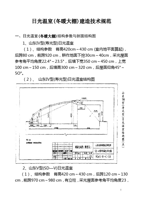
日光温室(冬暖大棚)建造技术规范一、日光温室(冬暖大棚)结构参数与剖面结构图1、山东Ⅳ型(寿光型)日光温室(1)、结构参数脊高420cm~430 cm (室内地平面算起),后跨80 cm,前跨920 cm,耕作地面下挖30cm~40cm,采光屋面参考角平均角度22.4°~23.5°,后墙下宽350 cm~450 cm,上宽100 cm~150 cm,后墙高300 cm~320 cm,后屋面仰角45°~5O°。
(2)、山东Ⅳ型(寿光型)日光温室结构图2、山东V型(SD—V)日光温室(1)、结构参数脊高420 cm~430 cm,后跨120 cm~130 cm,前跨970 cm~980 cm,有立柱,采光屋面参考角平均角度23,2。
23,9。
,后墙高290 cm~310 cm,后屋面仰角45°~47°。
(2)、山东V型日光温室剖面结构图二、日光温室选址与场地规划1、选址条件(1)位置符合NY5010—2002蔬菜产地环境条件的规定。
(2)土壤土层深厚,地下水位低,富含有机质,适合种植蔬菜的土壤,土壤的卫生标准应符合NY5010—2001的规定。
(3)其他周围无遮荫物;有较好的通风条件,但不要建在风口处;灌水、排水方便,水质符合GB 5084规定的标准;具备田间电源。
2、场地规划(1)温室面积日光温室长度以60 m~80m为宜,单位面积造价相对较低,室内热容量较大,温度变化平缓,便于操作管理。
(2)温室方位日光温室方位座北朝南,东西延长,其方位以正南向为佳;若因地形限制,采光屋面达不到正南向时,方位角偏东或偏西不宜超过5°。
(3)前后温室间距为防止前栋温室对后栋温室遮光,前后温室的间距应为前栋温室最高点高度的2.5~3倍。
三、日光温室的建造1、墙体(1)土墙可采用板打墙、草泥垛墙、土坯砌墙。
墙基部宽100 cm,向上逐渐收缩,至顶端宽8O cm。
设施农业(温室大棚)环境智能监控系统解决方案

设施农业(温室大棚)环境智能监控系统解决方案1、系统简介该系统利用物联网技术,可实时远程获取温室大棚内部的空气温湿度、土壤水分温度、二氧化碳浓度、光照强度及视频图像,通过模型分析,远程或自动控制湿帘风机、喷淋滴灌、内外遮阳、顶窗侧窗、加温补光等设备,保证温室大棚内环境最适宜作物生长,为作物高产、优质、高效、生态、安全创造条件。
同时,该系统还可以通过手机、PDA、计算机等信息终端向农户推送实时监测信息、预警信息、农技知识等,实现温室大棚集约化、网络化远程管理,充分发挥物联网技术在设施农业生产中的作用。
本系统适用于各种类型的日光温室、连栋温室、智能温室。
2、系统组成该系统包括:传感终端、通信终端、无线传感网、控制终端、监控中心和应用软件平台。
620)this.style.width=620;" border=0>(1)传感终端温室大棚环境信息感知单元由无线采集终端和各种环境信息传感器组成。
环境信息传感器监测空气温湿度、土壤水分温度、光照强度、二氧化碳浓度等多点环境参数,通过无线采集终端以GPRS方式将采集数据传输至监控中心,以指导生产。
(2)通信终端及传感网络建设温室大棚无线传感通信网络主要由如下两部分组成:温室大棚内部感知节点间的自组织网络建设;温室大棚间及温室大棚与农场监控中心的通信网络建设。
前者主要实现传感器数据的采集及传感器与执行控制器间的数据交互。
温室大棚环境信息通过内部自组织网络在中继节点汇聚后,将通过温室大棚间及温室大棚与农场监控中心的通信网络实现监控中心对各温室大棚环境信息的监控。
620)this.style.width=620;" border=0>(3)控制终端温室大棚环境智能控制单元由测控模块、电磁阀、配电控制柜及安装附件组成,通过GPRS模块与管理监控中心连接。
根据温室大棚内空气温湿度、土壤温度水分、光照强度及二氧化碳浓度等参数,对环境调节设备进行控制,包括内遮阳、外遮阳、风机、湿帘水泵、顶部通风、电磁阀等设备。
温室大棚内环境监测系统硬件设计外文文献

外文翻译毕业设计题目:温室大棚环境监测系统硬件设计原文:Environmental Monitoring and GreenhouseControl by DistributedSensor Network译文:环境监测与温室分布式传感器网络控制Environmental Monitoring and Green house Control by DistributedSensor Network(原文)A sensor is a miniature component which measure physical parameters from the environment. Sensors measure the physical parameters and transmit them either by wired or wireless medium. In wireless medium the sensor and its associated components are called as node. A node is self-possessed by a processor, local memory, sensors, radio, battery and a base station responsible for receiving and processing data collected by the nodes. They carry out joint activities due to limited resources such as battery, processor and memory. Nowadays, the applications of these networks are numerous, varied and the applications in agriculture are still budding. One interesting application is in environmental monitoring and green house control, where the crop conditions such as climate and soil do not depend on natural agents. To control and monitor the environmental factors, sensors and actuators are necessary. Under these circumstances, these devices must be used to make a distributed measure, spreading sensors all over the greenhouse using distributed clustering. This paper reveals an idea of environmental monitoring and greenhouse control using a sensor network. The hardware implementation shows periodic monitoring and control of greenhouse gases in an enhanced manner. Future work is concentrated in application of the same mechanism using wireless sensor network.Keywords—Sensor, sensor nodes, wireless sensor network (WSN), greenhouse control, environmental monitoring, CO 2monitoring, distributed clustering.I. INTRODUCTIONA sensor is able to convert physical or chemical readings gathered from the environment into signals that can be calculated by a system. A multi sensor node is able to sense several magnitudes in the same device. In a multi sensor, the input variables might be temperature (it is also able to capture nippy changes of temperature), fire, infrared radiation, humidity, smoke and CO2. A wireless sensor network could be an useful architecture for the deployment of the sensors used for fire detection and verification. The most vital factors for the quality and productivity of plant growth are temperature,humidity, light and the level of the carbon dioxide. Constant monitoring of these environmental variables gives information to the farmer to better understand, how each factor affects growth and how to manage maximal crop productiveness.The optimal greenhouse [3] climate adjustment can facilitate us to advance productivity and to achieve remarkable energy saving, particularly during the winter in northern countries. In the past generation greenhouses it was enough to have one cabled measurement point in the middle to offer the information to the greenhouse automation system. The system itself was typically simple without opportunities to manage locally heating, lights, ventilation or some other activity, which was affecting the greenhouse interior climate. The typical size of the greenhouse itself is much larger than it was before, and the greenhouse facilities provide several options to make local adjustments to the light, ventilation and other greenhouse support systems. However, additional measurement data is also needed to construct this kind of automation system to work properly. Increased number of measurement points must not dramatically augment the automation system cost. It should also be possible to easily alter the location of the measurement points according to the particular needs, which depend on the specific plant, on the possible changes in the external weather or greenhouse structure and on the plant placement in the greenhouse. Wireless sensor network can form a useful part of the automation system architecture in modern greenhouses constructively. Wireless communication can be used to collect the measurements and to communicate between the centralized control and the actuators located to the different parts of the greenhouse. In advanced WSN solutions, some parts of the control system itself can also be implemented in a distributed manner to the network such that local control loops can be formed. Compared to the cabled systems, the installation of WSN is fast, cheap and easy. Moreover, it is easy to relocate the measurement points when needed by just moving sensor nodes from one location to another within a communication range of the coordinator device. If the greenhouse vegetation is high and dense, the small and light weight nodes can even be hanged up to the plants’ branches. WSN maintenance is also relatively cheap and easy. The only additional costs occur when the sensor nodes run out of batteries (figure 1) and the batteries need to be charged or replaced, but the lifespan of the battery can be several years if an efficient power saving algorithm is applied. In this work, the very first steps towards the wireless greenhouse automation system by building a wireless measuring system for that purpose is taken and by testing its feasibility and reliability with a simple experimental setup.Clustering [11, 12] may be centralized ordistributed, based on the arrangement ofCH. In centralized clustering, the CH ispreset but in distributed clustering CH hasno fixed architecture. Distributedclustering mechanism is used for someprivate reasons like sensor nodes prone to Figure 1:Various components of a sensor nodefailure, better collection of data and minimizing redundant information. Hence these distributed clustering mechanisms encompass highly self-organizing capability.II. RELATED WORKS IN SENSOR NETWORKMilitary applications are very closely linked to the awareness of wireless sensor networks. In fact, it is very harsh to say for sure whether motes were developed because of military and air defense needs or whether they were invented separately and were subsequently applied to army services. Regarding military applications, the region of concentration extents from information collection, generally, to enemy tracking or battlefield surveillance. For example, mines could be regarded as unsafe and obsolete in the future and may be replaced by thousands of isolated sensors that will detect an intrusion of unreceptive units.Outdoor monitoring is an additional celestial area for applications of sensors networks. One of the most delegate examples is the operation of sensor nodes on Great Duck Island [8]. This sensor network has been used for environment monitoring. The sensor nodes used were talented to sense temperature, barometric pressure and humidity [1, 2]. In addition, passive infrared sensors and photo resistors were betrothed. The array was to monitor the natural environment of a bird and its activities according to climatic changes. For that cause, several motes were installed within birds’ burrows, to spot out the bird’s presence, while the rest were deployed in the nearby areas. Data are aggregated by the employment of sensor nodes and are passed through to a gateway.Management of costly possessions like equipment, machinery, different types of stock or products can be a quandary. The dilemma is highly distributed, as these companies enlarge all over the world. A gifted method to achieve asset tracking and cope with this trouble is believed to be with the use ofsensor networks. The application of wireless sensors in petroleum bunks and chemical warehouses refers to warehouses and cargo space administration of barrels. The thought is that motes attached to barrels will be gifted to locate nearby objects (other barrels), detecting their content and alerting in case of inappropriateness with their own, aging effects of the field etc.Health science and the health care system can also yield from the employment of wireless sensors. Applications in this class include telemonitoring human physiological data remotely, tracking and monitoring of doctors and patients within a hospital, drug superintendent in hospitals, etc. In Smart Sensors, retina prosthesis chip consisting of 100 micro sensors are built within the human eye. This allows patients with inadequate vision to see at an adequate level. Cognitive disorders, which almost certainly direct to Alzheimer’s, can be monitored and controlled at their premature stages with these wireless sensors.Robotic applications [9, 10] previously implemented are the unearthing of level sets of scalar fields using mobile sensor networks and imitation of the function of bacteria for looking for and discovering dissipative gradient sources. The tracking of a light source is completed with a few of the easy algorithms. In addition, a reply to the coverage crisis by robots and motes is accomplished for thick measurements over a broad area. The connection of both static and mobile networks is accomplished with the help of mobile robots, which travel around the environment and set up motes that act as beacons. The beacons support the robots to portray the directions. The mobile robots can perform as gateways into wireless sensor networks. Examples of such tasks are: sustaining energy resources of the wireless sensor network indefinitely, maintaining and configuring hardware, detecting sensor failure and appropriate deployment for connectivity amid the sensor nodes.Landslide detection employs sprinkled sensor system for predicting the happening of the landslides. The consideration of predicting landslides by means of sensor networks arose out of a must to mitigate the blemish caused by landslides to human lives and to the railway networks. A mixture of techniques from earth sciences, signal processing, distributed systems and fault-tolerance is used. One solitary trait of these systems is that it combines several distributed systems techniques to deal with the complexities of a distributed sensor network environment where connectivity is underprivileged and power budgets are very constrained, while fulfilling real-world requirements of safety. Generally these methods use a set of inexpensive single-axis strain gauges attached to cheap nodes, each with a CPU, battery and elite wireless transmitter block.Forest fires, also recognized as wild fires are wild fires occurring in wild areas and root major damage to natural and human resources. Forest fires wipes out forests, blaze the infrastructure and might result in high human death toll closer to urban areas. Common causes of forest fires embrace lightning, human carelessness and revelation of fuel to extreme heat and aridity. It is well known that in few cases fires are constituent of the forest ecosystem and they are important to the life cycle of native habitats.Sensor-Clouds can be used for health monitoring by using a quantity of simply obtainable and most often wearable sensors like accelerometer sensors, proximity and temperature sensors and so forth to collect patient’s health-related statistics for tracking sleep activity pattern body temperature and other respiratory conditions. These wearable sensor devices must have sustain of Bluetooth’s wireless interface, Ultra wideband and so forth interface for streaming of data, linked wirelessly to any smart phone through the interface. These smart phone devices foresee performing like a gateway between the remote server and sensor through the internet.III. EXPERIMENTAL SETUP IN A GREENHOUSEA. The Greenhouse EnvironmentA modern greenhouse [4-6] can consist of plentiful parts which contain their own local climate variable settings. As a result, a number of measurement points are also needed. This class of environment is challenging both for the sensor node electronics and for the short-range IEEE 802.15.4wireless network, in which communication range is greatly longer in open environments.B. SensorsHasty response time, low power consumption and tolerance against moisture climate, relative humidity and temperature sensor forms a perfect preference and solution for the greenhouse environment. Communication amid sensor and node can be carried out by IIC interface. Luminosity can be measured by light sensor, which converts light intensity to voltage. Unstable output signal is handled by low-pass filter to get correct luminosity values. CO2 measuring [7] takes longer time than other measurements and CO2 sensor voltage supply have to be within few volts. The carbon dioxide value can be read from the ensuing output voltage. Operational amplifier raises the voltage level of otherwise frail signal from the sensor.C. GreenhousesA greenhouse is a configuration covering ground frequently used for growth and progress of plants that will return the owner’s risk time and capital. This display is mounted with the purpose of protecting crop and of allowing a better environment to its progress. This shield is enough to promise a superior quality in production in some cases. However, when the major purpose is to achieve a better control on the horticulture development, it is necessary to test and control the variables that influence the development of a culture. The chief function of a greenhouse is to provide a more sympathetic environment than outside. Unlike what happens in traditional agriculture, where crop conditions and yield depend on nature resources such as climate, soil and others, a greenhouse ought to guarantee production independently of climatic factors. It is noteworthy to observe that even though a greenhouse protects crop from exterior factors such as winds, water excess and warmth it may cause plentiful problems such as fungus and excessive humidity. Therefore, mechanisms to scrutinize and control a greenhouse environment are incredibly vital to achieve better productivity. To get superior productivity and quality, better control system is necessary and as a result the production costs also get reduced. The chief elements involved in a greenhouse control system are: temperature, humidity, CO 2 concentration, radiation, water and nutrients.D. TemperatureTemperature is one of the most key factors to be monitored because it is unswervingly related to the growth and progress of the plants. For all plants, there is a temperature range considered best and to most plants this range is relatively varying between 10ºC and 30ºC. Among these parameters of temperature: extreme temperatures, maximum temperature, minimum temperature, day temperature and night temperature, difference between day and night temperatures are to be vigilantly considered.E. Water and HumidityAnother momentous factor in greenhouses is water. The absorption of water by plants is linked to the radiation. The lack or low level of water affects growth and photosynthesis. Besides air, the ground humidity also adjust the development of plants. The air humidity is interrelated to the transpiration while the ground humidity is connected to water absorption and photosynthesis. An atmosphere with extreme humidity decreases plants transpiration, reducing growth and may promote the proliferation of fungus. On the other hand, squat humidity level environments might cause dehydration.F. RadiationRadiation is a fundamental element in greenhouse production and sunlight is the key source of radiation. It is an important component for photosynthesis and carbon fixing. The significant radiation features are intensity and duration. The radiation intensity is linked to plant growth and the duration is openly associated with its metabolism.G. CO2 ConcentrationCO2 is an essential nutrient for plant development, allowing the assimilation of carbon. The carbon retaining procedure occurs through the photosynthesis when plants take away CO2 from the atmosphere. During the photosynthesis, the plant uses carbon and radiation to produce carbohydrate, whose function is to permit the plant development. Therefore, an enriched air environment should contribute to plant growth, but it is also vital to note that an extreme carbon level may turn the environment poisonous.IV. THE PROPOSED MODELA solution to the existing drawbacks can be found out from this proposed model. The proposed model is implemented in hardware, tested and the results show an excellent improvement in the sensing parameters when compared to the existing set of environmental monitoring and greenhouse control models. Sensor arrays like temperature sensor, light sensor, humidity sensor and vibration sensors are incorporated in the board. The sensed data is processed by the micro controller and displayed in the LCD display. Wireless transmission of the parameters is accomplished by a ZigBee module that sends information to the remote monitoring station periodically. To control and monitor the environmental variables planned in an earlier section, sensors and actuators capable of measuring and controlling the values inside the greenhouse are necessary. Generally, a greenhouse control is implemented just by approximating a measured cost to a reference or ideal cost. Figure 2, shows the basic block diagram of the proposed model. Due to cost considerations, the proposed model uses sensor network instead of wireless sensor network. The sensed data is forwarded to the gateway. The gateway then forwards the data to the remote monitoring base station. The base station is a remotely located software configured computer, where the monitored details are periodically visualized to carry out further control actions.Figure 2: Block diagram of the proposed modelIn the proposed model, the ideal assessment depends on the culture and type of plant. Control systems can be separated into centralized and distributed systems. In a centralized system a single constituent is responsible for gathering and processing the data. So, all the components of the system are connected to this solitary element. In a distributed control system the connections between nodes and information processing is distributed amongst the system components. The focal advantages of a distributed system may include: Reliability: a component failure affects barely part of the structure, Expansion: the likelihood of adding up of a new component without enormous changes in the system, Flexibility: changes in the procedure such as adding, removing and substituting of components impacts merely in the components involved in these basic operations. The major trouble of these technologies is that they are not developed for WSN and they do not present mechanisms to improve energy consumption.In this way, it is probable to check all places inside the greenhouse, identifying not only local values as in many applications, but checking real world and distributed values. Therefore, the greenhouse control ought to be improved, allowing a settlement in a way that the complete environment can be adjusted as close as feasible to a set point. It is essential to observe that, in most applications the sensors are placed in a point of a greenhouse and the measures gained are used to direct the entire greenhouse. However, even though in a controlled and relatively tiny place like a greenhouse, it is possible to have different values of climatic agents. Figure 3 shows the experimental setup forenvironmental monitoring.Figure 3: Experimental setup for environmental monitoringThus, the use of sensor in a greenhouse environment should permit a real time monitoring and an improved measurement through convenient distribution. The collected data in the system proposed must be sent to a base station located outside the greenhouse. The base station is connected by a gateway. With the implementation of this architecture, each node will be answerable for data collecting through its sensors and for sending it to its neighbors until all collected data emerge at the base station. The gateway generally uses wireless and Ethernet communication. The base station will be accountable for managing collected data, so some greenhouse control soft wares and some wireless actuators are necessary. In this application node defense will also be necessary to avoid damage by water and inputs. It is imperative to emphasize that the use of wireless sensors and actuators is advantageous to make the system installation trouble-free and to obtain flexibility and mobility in the nodes prototype. The difficulties in applying WSN in agricultural applications might include costs and lack of standardization on WSN communication protocols. Due to cost constraints, the proposed model is designed with sensors. In future, the same sensor network will be simulated in NS-2 for a distributed clustering mechanism. Wireless sensor network with temperature, moisture and light sensing and advanced capabilities will be implemented in real-time environment for green house monitoring in future.V. DISCUSSIONSThe major contributions of this manuscript are as follows. The design and implementation oflarge-scale and long-term CO2 monitoring sensor network is discussed. A low-cost sensor deployment strategy with guaranteed performance which addresses the sensor deployment problems in the existing models has been proposed. Hardware implementation of this model has been done and the parameters are periodically monitored with few sensors.VI. CONCLUSION AND FUTURE WORKA model of agricultural application using sensor networks for greenhouses monitoring and control was presented. The wireless sensor network technology, although under development, seems to be promising mainly because it allows real time data acquisition. However, for such agricultural application to be developed, some technological challenges should be resolved. A greenhouse is a controlled environment and does not require a lot of climatic parameters to be controlled. The use of this technology in large scale seems to be something for the near future. In this application, the great number of climatic parameters can be monitored using the sensors available. As a greenhouse is a relatively small and controlled environment, and energy is a limited resource, the possibility of replacing batteries or even resorting to a steady energy source adaptation is a constructive aspect. This paper reveals an idea of environmental monitoring and greenhouse control using a sensor network. The hardware implementation shows periodic monitoring and control of greenhouse gases in an enhanced manner. Future work is concentrated in application of the same mechanism using wireless sensor network. This technology can also be applied in breeding of confined animals in precision zoo, where the sensor nodes should send information about animal temperature, pressure and other vital signals to guarantee a healthy environment to animals. In order to attain better energy efficiency, this mechanism will be implemented in real-world wireless sensor network, with a well-known energy efficient distributed clustering mechanism (HEED).Author:CoimbatoreNationality:IndiaSource:Int. J. Advanced Networking and Applications V olume: 5 Issue: 5 Pages:2060-2065分布式传感器网络环境监测与温室控制(译文)传感器是一种微型组件可测量环境中的物理参数。
寿光第五代冬暖式温室大棚做法
为了增强对冬季严寒天气的应对能力,提高日光温室蔬菜的稳定水平,寿光盛荣温室工程有限公司专家对寿光第五代大棚做出总结以供参考。
一、日光温室建造结构参数日光温室按照墙体和建造方式的不同,分为砖砌空心墙和土墙下挖式两大类型。
(一)第五代砖砌空心墙日光温室室内跨度11m,其中后跨1.2~1.3m,前跨9.7~9.8m;脊高4.2~4.3m,后墙高2.9~3.1m,后屋面仰角45°~47°。
室内跨度加大,应加强温室抗压能力。
若用钢架结构,可在前后屋面交界处(即脊高处)设一排立柱,并在前屋面距前沿3m处设一排活动立柱(夏季拆除),以防大雪压垮温室前屋面。
墙体具承重、隔热、蓄热功能。
砖砌空心墙内墙宽为37cm,外墙为24cm,中间留20~30cm空心,可随砌墙随填蛭石或珍珠岩,或安放10cm聚板。
为使墙体坚固,内外墙体之间可每隔3m砌砖垛,连接内外墙,也可用水泥预制板拉连。
后屋面(后坡)具承重、隔热、蓄热、防雨雪等功能,应由蓄热材料、隔热材料、防漏材料组成,总厚度应达到50~60cm。
用于越冬喜温蔬菜栽培的新建和改建日光温室,不能忽视后屋面的建造和作用。
(二)土墙下挖式第五代日光温室近年来,土墙下挖式日光温室发展很快,其突出特点是建造成本低,保温效果好。
建造土墙下挖式日光温室必须具备土层深厚、土质均匀、地下水位低等基本条件。
而且,土墙厚度、下挖深度和温室跨度应当适度。
室内跨度11m,其中后跨1m,前跨10m;脊高4.6m(从室内地面算起),下挖0.6~1m;土墙底宽4.0~5.0m,土墙上宽1.5~2.0m,后墙高3.2~3.5m,后屋面仰角45°~50°。
因温室跨度加大,应合理安排立柱,以加强抗风雪能力。
须注意,在黄河冲积的沙质土壤上不宜建造土墙下挖式日光温室,原因是土墙遇大雨被水浸后易塌墙。
若要建,则应在内墙砌砖墙和在外墙覆盖塑料薄膜防雨,以免雨水浸墙。
另外,在建土墙下挖式日光温室时,为避免下挖过深造成前沿遮荫,可将温室前3m宽的地面下挖0.8m左右,将土填入温室内,或用做墙土。
日光温室(冬暖大棚)建造技术规范
日光温室(冬暖大棚)建造技术规范一、日光温室(冬暖大棚)结构参数与剖面结构图1、山东Ⅳ型(寿光型)日光温室(1)、结构参数脊高420cm~430 cm (室内地平面算起),后跨80 cm,前跨920 cm,耕作地面下挖30cm~40cm,采光屋面参考角平均角度22.4°~23.5°,后墙下宽350 cm~450 cm,上宽100 cm~150 cm,后墙高300 cm~320 cm,后屋面仰角45°~5O°。
(2)、山东Ⅳ型(寿光型)日光温室结构图2、山东V型(SD—V)日光温室(1)、结构参数脊高420 cm~430 cm,后跨120 cm~130 cm,前跨970 cm~980 cm,有立柱,采光屋面参考角平均角度23,2。
23,9。
,后墙高290 cm~310 cm,后屋面仰角45°~47°。
(2)、山东V型日光温室剖面结构图二、日光温室选址与场地规划1、选址条件(1)位置符合NY5010—2002蔬菜产地环境条件的规定。
(2)土壤土层深厚,地下水位低,富含有机质,适合种植蔬菜的土壤,土壤的卫生标准应符合NY5010—2001的规定。
(3)其他周围无遮荫物;有较好的通风条件,但不要建在风口处;灌水、排水方便,水质符合GB 5084规定的标准;具备田间电源。
2、场地规划(1)温室面积日光温室长度以60 m~80m为宜,单位面积造价相对较低,室内热容量较大,温度变化平缓,便于操作管理。
(2)温室方位日光温室方位座北朝南,东西延长,其方位以正南向为佳;若因地形限制,采光屋面达不到正南向时,方位角偏东或偏西不宜超过5°。
(3)前后温室间距为防止前栋温室对后栋温室遮光,前后温室的间距应为前栋温室最高点高度的2.5~3倍。
三、日光温室的建造1、墙体(1)土墙可采用板打墙、草泥垛墙、土坯砌墙。
墙基部宽100 cm,向上逐渐收缩,至顶端宽8O cm。
智能温室大棚环境监测系统
智能温室大棚环境监测系统一、产品介绍智能温室大棚环境监测系统是由超声波气象传感器、土壤温度水分传感器、土壤温度水分电导率三合一变送器、气象监控主机和LED显示屏构成,可以实现对温室大棚内的温度、湿度、光照、土壤温度、土壤含水量、CO,浓度等与农作物生长紧密相关环境参数的实时采集,并将数据实时上传竞道农业四情测报平台。
二、监测内容针对温室大棚的空气温度、湿度、二氧化碳和光照强度的连续监测实时告警。
三、监测效果通过安装超声波气象传感器对温室大棚环境温度、湿度、二氧化碳和光照强度进行实现监测。
变送器通过RS485智能接口及通讯协议接入气象监控主机,由4G无线传输或RJ45网口将数据上传至服务器,发送到农业四情测报平台进行实时监测。
当温度、湿度、二氧化碳和光照强度超过设置的上下阈值时,系统自动触发短信、语音、邮件告警,通知管理人员紧急处理。
四、监测功能超声波气象传感器采纳ASA工程塑料材质,体积小、重量轻,采纳优质抗紫外线材质,使用寿命长,采纳高灵敏度的探头,信号稳定,精度高。
关键部件采纳进口器件,稳定牢靠,具有测量范围宽、线形度好、防水性能好、使用便利、便于安装、传输距离远等特点。
五、监测参数空气温度:—40—60℃(0.3℃);2、空气湿度:0—100%RH(3%RH);3、PM2.5:0—1000ug/m3(10%)4、PM10:0—1000ug/m3(10%)5、土壤水分:测量范围:0—100%,精度:3%,探针长度:5.5cm,探针直径:3mm,探针材料:不锈钢6、土壤温度:测温范围—40+125℃,测量精度0.5℃,辨别率:0.1℃7、土壤电导率:测量范围可选量程:0—5000us/cm,10000us/cm,20000us/cm,测量精度0—10000us/cm范围内为3%;10000—20000us/cm范围内为5%,辨别率0—10000us/cm内10us/cm,100000—20000us/cm内50us/cm。
大棚温室温室内温度、湿度、光照、土壤温度、土壤湿度、CO2浓度、叶面湿度、露点温度监测系统
大棚温室温室内温度、湿度、光照、土壤温度、土壤湿度、CO2浓度、叶面湿度、露点温据处理。
9:控制软件的编制采用软件工程管理,开放性与可扩充性极强,由于采用硬件功能的软件化的系统设计思想及系统硬件的模块化、通讯网络化设计,系统可根据需要升级软件功能与扩展硬件种类。
10:系统设计时预留有接口,可随时增加减硬软件设备,系统只要做少量的改动即可,可以在很短的时间内完成。
可根据政策和法规的改变随时增加新的内容。
11:设备改进、检修过程中及检修完成后,均不需要停止或重新启动机房监控系统。
12:系统都均做可靠行接地,以防静电。
产品其他应用场合:4:数据集中器端提供具有信号输出协议的端口,可接通信设备(GPRS DTU等)进行无线传输。
5:温湿度监控软件采用标准windows 98/2000/XP全中文图形界面,实时显示、记录各监测点的温湿度值和曲线变化,统计温湿度数据的历史数据、最大值、最小值及平均值,累积数据,报警画面。
6:监控主机端利用监控软件可随时打印每时刻的温湿度数据及运行报告。
7:温湿度记录仪强大的数据处理与通讯能力,采用计算机网络通讯技术,局域网内的任何一台电脑都可以访问监控电脑,在线查看监控点位的温湿度变化情况,实现远程监测。
系统不但能够在值班室监测,领导在自己办公室可以非常方便地观看和监控。
6辅材订制1批 KITOZER/广州1000.001000.00小计8070.00143660.0035915.0012138.40191713.40四、以上全部设备合计:五、运输安装调试费=全部设备总合计*25%六、税金=(全部设备总合计+运输安装调试费)*8%七、系统工程总价=全部设备总合计+运输安装调试费+税金地址:广州市公司简介:广州莱安智能化系统开发有限公司成立于是2002年,专业从事各种应用传感器、设备环境监测、数字网络视频监控系统、雷达测速、闯红灯电子警察抓拍、电子治安卡口、智能控制等智能化设计系统开发以及生产的大型综合型企业,欢迎来电洽谈业务!用户服务中心:Tel:020-******** 85574628 85574638露点温度监测系统员;其它电脑。
- 1、下载文档前请自行甄别文档内容的完整性,平台不提供额外的编辑、内容补充、找答案等附加服务。
- 2、"仅部分预览"的文档,不可在线预览部分如存在完整性等问题,可反馈申请退款(可完整预览的文档不适用该条件!)。
- 3、如文档侵犯您的权益,请联系客服反馈,我们会尽快为您处理(人工客服工作时间:9:00-18:30)。
冬暖式温室大棚环境监测
物理学院2006级
组员丁宅伟刘旺梁传慧指导老师李茂奎
一、目的:
1在国家大力发展农业的背景之下,我们所做的这个项目是很有意义的
2应用所学单片机知识,将所学应用到实践中,培养实践与动手能力,真正把理论转化为实践。
3通过单片机课程设计,熟练掌握ICC A VR C语言的编程方法,将理论联系到实践中去,提高我们的动脑和动手的能力。
二、功能及用途:主要功能是监测大棚的温度并显示,用测得的光敏电阻的阻值表征
光照强度,应用于普通冬暖式温室大棚的温度监测和光照自动控制,另有定时功能可以设定允许触发的时间范围。
三、原理:应用avr单片机作为核心处理器,使用ds18b20传感器将所收集的信号传送
给单片机,然后实现温度的显示,用光敏电阻在光照下阻值的变化转化成电压变化输入到单片机,进行处理转化将其限定在一定范围内,超出范围就会发出警报。
可以定时只允许在设定的时间范围内触发单片机引起报警及相关装置的动作
四、硬件设计:
1、设计思路:
(1)mega16单片机核心处理
(2)数码管显示温度光强数值
(3)独立按键设置温度光强的上下限值
(4) led指示灯和蜂鸣器报警
(5)电动机正反转拉上或拉下大棚草帘
(6)定时功能设定天亮天黑时间
2、方案论证与设计:
方案一:用四位数码管显示
优点:程序简单,很经济
缺点:不能同时显示多个数值
方案二用LCD显示
优点:能同时显示多个数值,方便
缺点:价格昂贵程序复杂
综合以上要素和实际情况我们选择方案一
3、核心硬件的设计:
avr单片机作为处理器,ds18b20作为温度输入,cds5516光敏电阻检测光照
4、键盘电路的设计:
由于系统要求功能比较简单,所以采用独立式4个按键
5、显示电路的设计:
显示电路采用四位数码管显示
硬件PCB图
系统实物图
五.如何使用硬件单元:A键切换数码管的显示状态,分别显示的状态是当前气温、
设置温度上限值、设置温度下限值、用光敏电阻阻值表征的光照强度(阻值越大光照越强,通过查“照度—电阻特性图”来确定光照强度)、当前时间、设定天亮时间、设定天黑时间;
B、C键分别设置气温值的十位和个位;D键消除警报;温度超出范围led1亮,蜂鸣器响;光照超出范围led2亮,蜂鸣器响。
六.软件设计思想:
1.用按键触发外部中断,切换显示状态,
2.用定时器比较匹配中断调用显示函数
3.用ADC测量光敏电阻的阻值用以表征光照强度
4.用键盘设定温度和光照上下限值
5.如果温度和光照超标就触发报警装置并且电机会相应转动,拉开或拉上草帘
6.用键盘设定天亮天黑时间
软件设计框图
7.
8.ds18b20程序流程图
9.光照部分的程序流程图
10.
七.测试过程及数据:
光照(用电阻值表征光强,显示的是电阻值)
八.分析相应指标及参数:
单键对应的端口是PB2、PD3、PD4、PD6;
LED对应的端口是PC0、PC1;
蜂鸣器 PC6;
光敏电阻,电阻,电容0.1微法,电感0.1mh,蜂鸣器,温度传感器ds18b20,三极管0.5w 的参数
九.所需全部资源及成本:
数码管2元,单片机,独立式按键0.15*4,发光二极管2元,蜂鸣器0.3,电烙铁,焊锡,电阻1元,电容1元,电感5个1元
十.成员分工和工作情况及贡献:
软件设计:丁宅伟 40%
硬件焊接:刘旺 30%
论文撰写:梁传慧 30%
十一。
心得体会
通过单片机课程设计,我们不仅加深了对单片机理论的理解,将理论很好地应用到实际当中去,而且我们还学会了如何去培养我们的创新精神,从而不断地战胜自己,超越自己。
创新,是要我们学会将理论很好地联系实际,并不断地去开动自己的大脑,从为人类造福的意愿出发,做自己力所能及的,别人却没想到的事。
使之不断地战胜别人,超越前人。
同时,更重要的是,我在这一设计过程中,学会了坚持不懈,不轻易言弃。
设计过程,也好比是我们人类成长的历程,常有一些不如意,也许这就是在对我们提出了挑战,勇敢过,也战胜了,胜利的钟声也就一定会为我们而敲响。
课程设计是培养学生综合运用所学知识,发现,提出,分析和解决实际问题,锻炼实践能力的重要环节,是对学生实际工作能力的具体训练和考察过程.随着科学技术发展的日新日异,单片机已经成为当今计算机应用中空前活跃的领域,在生活中可以说得是无处不在。
因此作为二十一世纪的大学来说掌握单片机的开发技术是十分重要的。