CH6数显仪参数资料
美国奥特诺(Eaton)PXM 4 6 8K 电能表6寸彩色触摸屏显示器说明书

ContentsDescription P age 1 Introduction . . . . . . . . . . . . . . . . . . . . . . . . . . . .22 Installation . . . . . . . . . . . . . . . . . . . . . . . . . . . . .23 Using the Touchscreen . . . . . . . . . . . . . . . . . . .2PXM 4/6/8K Meter 6" ColorTouchscreen Display Features2Instruction Booklet IB150004ENEffective February 2015PXM 4/6/8K Meter 6" Color Touchscreen Display FeaturesEATON 1 IntroductionThe Eaton PXM 4/6/8K Meter 6” Color Touchscreen Display is pre-programmed to communicate with Eaton PXM 4/6/8K Meters . The programming allows access to data concerning the meter to which it is connected as well as power quality, I/O (input/output), and events .The built-in navigation functions are simple and convenient and allow for easy navigation between the screens . It has been designed to display data, power quality, I/O (input/output) and events from a single Power Xpert 4/6/8K Meter .2 InstallationFor installation and connection information, please refer to “PXM 4/6/8K Meter Color Touchscreen Display Quick Starts Guide” (Eaton Pub . # TD150015EN) .3 Using the Touchscreen3.1 Basic NavigationBasic navigation between the screens is accomplished by touching the name of the screen or category area; the back, next, or previous arrows; or the home icon .Touching a screen name or category area will take the User to the screen or category selected (see Figure 1) .Figure 1. Navigating from the Home Screen to the Meter, Quality, I/O, and Events Screens.Touching the Home icon, where available, will return the User to the Home screen .Figure 2. Location of the Home Icon Available on the Main Sub-screens.Touching the “Back” arrow will return the User to the previous cat-egory screen . Touching the “Next” arrow will take the User to the next Data screen . Touching the “Previous” arrow with take the User to the previous Data screen .Figure 3. Location of the Back, Previous, and Next Arrows.3.1.1 Accessing Trend InformationTrend information is accessed by touching the data for which trend information is desired .otee:N Tables 1, 2, and 3 identify all data for which trend information is avail-able .BackMeterQualityI/OEventsHome IconNextPrevious3Instruction Booklet IB150004ENEffective February 2015PXM 4/6/8K Meter 6" Color Touchscreen Display Features EATON Figure 4. Selecting Data to Access T rend Information.Figure 5. T ypical Data T rend Screen.3.1.2 Screen and Backlight SaverIf the touchscreen has not been used for 60 minutes, the screen and backlight saver will activate and the touchscreen will become blank and the backlight will turn off . To reactivate the touchscreen and backlight, simply touch any area of the touchscreen .3.2 The Home ScreenThe Home screen appears when power has been applied to the PXM 4/6/8K Meter 6" Color Touchscreen Display and boot-up iscomplete . The Home screen displays the main data for the meter to which it is connected . This data includes:• Voltage (L -L) Average (V);• Voltage (L -N) Average (V);• Current Average (A);• Real Power (kW);• Apparent Power (kVA);• Power Factor (Lead/Lag); and •Real Energy (kWh) .otee:N Trend information is available from the Home screen for all displayed data except Real Energy . To access the trend data, touch the touchscreen area corresponding to the data trend desired .Figure 6. The Home Screen.In addition, the Home screen also gives the User direct access to the Meter, Quality, I/O, and Events screens . These are accessed by touching the name areas at the bottom of the screen .The Home screen also gives the User access to the system settings .The user can make adjustments to the following settings:• Screen Brightness and Contrast;• Touch Panel Sensitivity;• COM Port;• Audio Volume; and •Screen Saver Time .3.3 The Meter ScreenTouching the “Meter” area on the Home screen takes the User to the Meter screen . The categories of data available from the Meters screen are:•Voltage;• Current;• Frequency;• Phasors;• Power Factor;• Power;• Energy;• Demand; and •Peak Demand .Vavg (L -N) Data Area to Touch for Trend Information4Instruction Booklet IB150004ENEffective February 2015PXM 4/6/8K Meter 6" Color Touchscreen Display FeaturesEATON Figure 7. The Meter Screen.T able 1. Data Available from the Meter Screen.Meter CategoryDataTypeValues Trend AvailableVoltage Voltage (L-L)Vavg, Vab, Vbc, and Vca Present, Minimum, and Maximum Values Yes Voltage (L-N)Vavg, Van, Vbn, Vcn, and Vng Present, Minimum and Maximum Values Yes Voltage (Aux L-L)*Vavg, Vab, Vbc, and Vca Present, Minimum and Maximum Values Yes Voltage (Seq Comp [Sequence Components])ZERO-SEQ, POS-SEQ, NEG-SEQYes Current I(RMS)Iavg, Ia, Ib, Ic, In, and Ig Present, Minimum, and Maximum Values Yes I(Seq Comp [Sequence Components])ZERO-SEQ, POS-SEQ, NEG-SEQ Yes Frequency Frequency HzPresent, Minimum, and Maximum Values YesPhasors Phasors Va, Vb, and Vc Magnitude and Degree (with Phasor Diagram)Ia, Ib, and IcMagnitude and Degree (with Phasor Diagram)Power Factor Displacement System, Phase A, Phase B, and Phase C Present, Minimum, and Maximum Yes Apparent System, Phase A, Phase B, and Phase C Present, Minimum, and Maximum Yes PowerReal Total, Phase A, Phase B, and Phase C Present Yes Apparent Total, Phase A, Phase B, and Phase C Present Yes ReactiveTotal, Phase A, Phase B, and Phase C Present YesEnergyReal Forward, Reverse, Net, and Sum Present Apparent TotalPresent ReactiveReceived, Delivered, Net, and Sum PresentDemandReal Forward, Reverse, Net, and Sum Present and Peak Today Apparent TotalPresent Reactive Received, Delivered, Net, and Sum Present Values AmpAverage DemandPresent and Peak TodayPeak DemandReal Forward, Reverse, Net and Sum Peak Since Last Reset and Time of Peak Last Reset Date and Time of Last ResetApparent Total Peak Since Last Reset and Time of Peak Last ResetDate and Time of Last Reset Reactive Received, Delivered, Net, and Sum Present Value and Time of Peak Last Reset Date and Time of Last ResetAmpAverage Demand Peak Since Last Reset and Time of Peak Last ResetDate and Time of Last Reset* For meters equipped with Auxiliary voltage channels.For the data available for each category, the data, type of data, val-ues, and available trend information, please refer to Table 1 – Data Available from the Meter Screen .From the Meter screen, the User can navigate back to the Home screen by touching the Home icon (see Figure 2) . The User canalso navigate to the Quality, I/O, and Events screens by touching the appropriate screen name area (see Figure 1) .3.4 The Quality ScreenTouching the “Quality” area on the Home screen takes the User to the Quality screen . The categories of data available from the Quality screen are:• Factor;• Flicker;• THD Current; and •THD Voltage .5Instruction Booklet IB150004ENEffective February 2015PXM 4/6/8K Meter 6" Color Touchscreen Display Features EATON Figure 8. The Quality Screen.T able 2. Data Available from the Quality Screen.Quality CategoryDataValuesTrend AvailableFactor K-Factor Phase A, Phase B, and Phase C Yes Crest Factor Phase A, Phase B, and Phase C Yes ITIC FactorPhase A, Phase B, and Phase C YesFlicker*Perceptibility Total, AB, BC, CA, AN, BN, and CN Yes (Except Total)PST Total, AB, BC, CA, AN, BN, and CN Yes (Except Total)PLTTotal, AB, BC, CA, AN, BN, and CN THD Current Total Amps Phase A, Phase B, Phase C, and Neutral Yes Odd Amps Phase A, Phase B, Phase C, and Neutral Yes Even Amps Phase A, Phase B, Phase C, and Neutral Yes Interharmonic Amps Phase A, Phase B, Phase C, and Neutral Yes Total Percentage Phase A, Phase B, Phase C, and Neutral Yes Odd Percentage Phase A, Phase B, Phase C, and Neutral Yes Even Percentage Phase A, Phase B, Phase C, and Neutral Yes Interharmonic PercentagePhase A, Phase B, Phase C, and Neutral Yes THD Voltage Main L-L VoltsTotal Volts AB, BC, and CA Yes Odd Volts AB, BC, and CA Yes Even Volts AB, BC, and CA Yes Interharmonic VoltsAB, BC, and CA Yes Aux L-L Volts Total Volts AB, BC, and CA Yes Odd Volts AB, BC, and CA Yes Even Volts AB, BC, and CA Yes Interharmonic VoltsAB, BC, and CA Yes Main L-N Volts Total Volts AN, BN, and CN Yes Odd Volts AN, BN, and CN Yes Even Volts AN, BN, and CN Yes Interharmonic VoltsAN, BN, and CN Yes Percentage L-L Total Percentage AB, BC, and CA Yes Odd Percentage AB, BC, and CA Yes Even Percentage AB, BC, and CA Yes Interharmonic PercentageAB, BC, and CA Yes Percentage Aux.Total Percentage AB, BC, and CA Yes Odd Percentage AB, BC, and CA Yes Even Percentage AB, BC, and CA Yes Interharmonic PercentageAB, BC, and CA Yes Percentage L-N Total Percentage AN, BN, and CN Yes Odd Percentage AN, BN, and CN Yes Even Percentage AN, BN, and CN Yes Interharmonic PercentageAN, BN, and CNYes* PXM 6000 and above.For the data available for each category, the type of data, values, and available trend information, please refer to Table 2 – Data Available from the Quality Screen .From the Quality screen, the User can navigate back to the Home screen by touching the Home icon (see Figure 2) . The User can also navigate to the Meter, I/O, and Events screen by touching the appro-priate screen name area (see Figure 1) .6Instruction Booklet IB150004ENEffective February 2015PXM 4/6/8K Meter 6" Color Touchscreen Display FeaturesEATON 3.5 The I/O ScreenTouching the “I/O” (Input/Output) area on the Home screen takes the User to the I/O screen . The categories of data available from the I/O screen are:• Current Input Status and •Current Output Status .Figure 9. The I/O Screen.For the data available for each category, the type of data, values, and available trend information, please refer to Table 3 – Data Available from the I/O Screen .T able 3. Data Available from the I/O Screen.I/O CategoryDataTypeValuesTrend AvailableCurrent Input Status Current Inputs Inputs 1through 8Status and CountCurrent Output Status Current Outputs Output 1 through 3StatusSolid State 1 and 2StatusFrom the I/O screen, the User can navigate back to the Homescreen by touching the Home icon (see Figure 2) . The User can also navigate to the Meter, Quality, and Events screen by touching theappropriate screen name area (see Figure 1) .3.6 The Events ScreenTouching the “Events” area on the Home screen takes the User to the Events screen 1 . There are five events screens . Each Events screen can display four events for a total of 20 events recorded .Figure 10. T ypical Events Screen (Events Screen 1 Shown).Each event has an ID (identification number), short event detail, and the time the event occurred (see Table 4) . Each event may also be viewed in a separate window displaying the event ID, when the event occurred, and a long event message . The Event Messagescreens are accessed by touching the Event Detail area for the event listed on the Events screens .T able 4. Event Information Available on the Events Screens.EventTypeInformationAssociated Event Message ScreenEvents Screen 1 through 5Messages (Up to 4)Event ID Event Detail (Short) Time Occurred Event ID Event Message (Long)Event Occurred (Time)The event triggers for the PXM 4/6/8K Meter 6" Color Touchscreen Display are listed in Table 5 .Figure 11. Typical Event Message Screen.7Instruction Booklet IB150004ENEffective February 2015PXM 4/6/8K Meter 6" Color Touchscreen Display Features EATON T able 5. Event T riggers.ScreenCategoryItemEvent Trig g erMeter Voltage Line-LineSystemAB - Upper and Lower BC - Upper and Lower CA - Upper and Lower Line-NeutralSystemAN - Upper and Lower BN - Upper and Lower CN - Upper and Lower NG - Upper and Lower Aux Line-LineSystemAB - Upper and Lower BC - Upper and Lower CA - Upper and LowerSymmetric ComponentsV0 - Upper Zero Sequence Component V1 - Upper Positive Sequence Component V2 - Upper Negative Sequence ComponentCurrentAverage - Upper Phase A - Upper Phase B – Upper Phase C - Upper Neutral - Upper Ground - Upper Symmetric Components I0 - Upper Zero Sequence Component I1 - Upper Positive Sequence Component I2 - Upper Negative Sequence ComponentCurrent Unbalance - UpperFrequencyUpper and Lower PowerRealSystem - UpperPhase A - Upper Phase B - Upper Phase C - UpperReactiveSystem - UpperPhase A - Upper Phase B - Upper Phase C - UpperApparentSystem - UpperPhase A - Upper Phase B - Upper Phase C - UpperPower FactorApparentSystem - Leading and Lagging Phase A - Leading and Lagging Phase B - Leading and Lagging Phase C - Leading and Lagging DisplacementSystem - Leading and Lagging Phase A - Leading and Lagging Phase B - Leading and Lagging Phase C - Leading and Lagging8Instruction Booklet IB150004ENEffective February 2015PXM 4/6/8K Meter 6" Color Touchscreen Display FeaturesEATON T able 5. Event T riggers.ScreenCategoryItemEvent Trig g erQuality THD Voltage Line - LineSystemPhase AB - Upper and Lower Phase BC - Upper and Lower Phase CA - Upper and Lower Line-NeutralSystemPhase AN - Upper and Lower Phase BN - Upper and Lower Phase CN - Upper and LowerTHD CurrentSystem - Upper Phase A - Upper Phase B - Upper Phase C - Upper Flicker Perceptibility*Line - LineSystemPhase AB - Upper and Lower Phase BC - Upper and Lower Phase CA - Upper and Lower Line - NeutralSystemPhase AN - Upper and Lower Phase BN - Upper and Lower Phase CN - Upper and LowerDemand OverloadReal Power Forward Real Power Reverse Real Power Net Real Power Sum Real Power Delivered Real Power Received Reactive Power Net Reactive Power Sum VA Current ITIC*L2 Sags L4 Sags L8 Sags L2 Swells L4 Swells L8 Swells Sub-cycle Disturbance dV/dt Threshold Absolute Threshold Fast Transient**Vag dV/dt Vag Absolute Vbg dV/dt Vbg Absolute Vcg dV/dt Vcg Absolute Vng dV/dt Vng Absolute SEMI F47Sags Discrete Inputs StatusManual CapturesMeter Access (Log-in, log-out, Access of IP address)* PXM 6000 and above.* PXM 8000.From Events screens 1 through 5, the User can navigate to the Meter, Quality, and I/O screen by touching the appropriate screen name area (see Figure 1) .otee:N The User can not go directly from any Events screens to the Home screen . The User must first access the Meter, Quality, or I/O screens then return to the Home screen .(Cont.)9Instruction Booklet IB150004ENEffective February 2015PXM 4/6/8K Meter 6" Color Touchscreen Display Features EATON Notese:10Instruction Booklet IB150004ENEffective February 2015PXM 4/6/8K Meter 6" Color Touchscreen Display FeaturesEATON Notese:11Instruction Booklet IB150004ENEffective February 2015PXM 4/6/8K Meter 6" Color Touchscreen Display Features EATON Notese:EatonElectrical Sector1000 Eaton Boulevard Cleveland, OH 44122United States877-ETN-CARE (877-386-2273) © 2015 EatonAll Rights ReservedPrinted in USAPublication No. IB150004EN / TBG001199 February 2015Eaton is a registered trademark.All other trademarks are property of their respective owners.Instruction Booklet IB150004EN Effective February 2015PXM 4/6/8K Meter 6" Color Touchscreen Display FeaturesThe information, recommendations, descriptions, and safety nota-tions in this document are based on Eaton’s experience and judg-ment . This instructional literature is published solely for information purposes and should not be considered all-inclusive . If further infor-mation is required, you should consult an authorized Eaton sales representative .The sale of the product shown in this literature is subject to the terms and conditions outlined in appropriate Eaton selling policies or other contractual agreement between the parties . This literature is not intended to and does not enlarge or add to any such contract . The sole source governing the rights and remedies of any purchaser of this equipment is the contract between the purchaser and Eaton . NO WARRANTIES, EXPRESSED OR IMPLIED, INCLUDING WARRANTIES OF FITNESS FOR A PARTICULAR PURPOSE OR MERCHANTABILITY, OR WARRANTIES ARISING FROM COURSE OF DEALING OR USAGE OF TRADE, ARE MADE REGARDING THE INFORMATION, RECOMMENDATIONS, AND DESCRIPTIONS CONTAINED HEREIN.In no event will Eaton be responsible to the purchaser or user in contract, in tort (including negligence), strict liability or otherwise for any special, indirect, incidental or consequential damage or loss whatsoever, including but not limited to damage or loss of use of equipment, plant or power system, cost of capital, loss of power, additional expenses in the use of existing power facilities, or claims against the purchaser or user by its customers resulting from the use of the information, recommendations and description contained herein .The information contained in this manual is subject to change without notice .。
CONTRONIX说明书

)仪表与2线制变送器电流信号的接线
A-S规格80×160尺寸的仪表(mm)
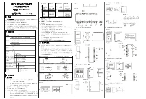
外形尺寸
开孔尺寸接线端子图
B-F规格96
外形尺寸
开孔尺寸接线端子图
开孔尺寸接线端子图
、
键调出当前参数的原设定值,闪烁位为修正位
通过键移动修改位,键增值、
键存入修改好的参数,自动转到下一参数。
键后将转到本组第
重复②
,直到显示
键进入修改状态,,,
密码在仪表上电时或
不松开,顺序进入各参数组,仪表显
键调出当前参数的原设定值,闪烁位为修改位
通过键移动修改位,键增值,
以符号形式表示参数值的参数,在修改时,闪烁位应处于末位。
重复④~ 以下为测量及显示相关参数,设置不正确,可能使仪表显示不正常。
、
种:
变送输出
变送输出有5个参数:
)——输出信号选择
补偿前温度+
影响,该温度可能会高于室温。
在实际应用中,补偿导线接到输入端子,仪。
XMT-618T系列时间温度使用说明书中文

XMT*618T系列智能数显时间温度调节仪(使用此产品前,请仔细阅读说明书,以便正确使用,并请妥善保存,以便随时参考)一、概述XMT*608T系列智能数显时间温度调节仪为智能型双排三位显示仪表,分别显示温度测量值和运行时间倒计时;仪表可多种信号输入,并提供多种时间控制方式选择,仪表三键操作,采用二位式、PID控制;参数设置简易,输入信息方便等功能,广泛应用于机械、化工、陶瓷、轻工、冶金、石化,热处理等行业的温度自动控制系统。
二、要技术参数1、测量误差:±0.5F·S±1字,附加冷端补偿误差±1℃2、输入类型(可选):CU50(-50~150)、PT100(-80~600)、K(-30~999)、E(-30~700)、J(-30~900)、T(-199~400)3、继电器输出(无源)触点容量:AC220V5A(阻性负载)周期2~120秒可调4、时间范围:0~999秒或0~999分(可选)5、固态继电器驱动信号:电流大于15mA空载电压大于12V,周期约2S6、工作电源:AC85~242V,50/60Hz功耗<3W7、工作环境:0~50℃,相对湿度≤85%,无腐蚀性及无强电磁辐射场合三、仪表面板介绍1、仪表面板(参考)2、仪表接线(参考)★仪表具体接线以仪表外壳上接线图为准四、产品型号定义XMT□—6□8□123451:为外型尺寸标号空:160×80×85开孔156×76A:96×96×80开孔92×92D:72×72×80开孔68×68E:48×96×75开孔44×92F:96×48×75开孔92×44G:48×48×110开孔44×44S:80×160×85开孔76×156B:60×120×90开孔56×156L:标准35mmDIN导轨安装C:80×120×35壁挂式安装2:操作显示方式:‘6’三键轻触开关设定,双排三位数字显示,PID控制3:为附加报警‘1’无报警但有一组时间控制输出;‘5’无报警但有一组时间控制蜂鸣器输出4:输入信号类型:‘8’输入信号自由互换(暂无电压、电流信号输入)5:后缀空:继电器输出G:固态继电器输出T:时间控制功能五、内部参数表5-1序号提示符名称设定范围说明出厂值一级菜单0温度设定值由、决定按▲键3秒直接可修改设定值随机1时间设定0~999按▼键3秒直接可修改设定值随机二级菜单2温度上限报警0~100超过报警点时有触点转换输出,同时报警灯亮(有报警功能时才有触点转换输出),报警功能在=0时有意义。
氯离子测定仪说明书

弘扬高科技企业之宗旨凭籍卓越质量品质迅速风靡煤质设备市场奉行低价位之经营策略遵循无限服务理念全面拓展煤质设备领域YXFL-6H氟氯离子测定仪使用说明书中国·河南市永心电子科技制造用心服务永心目录第一章简介01.1产品概述01.2测试原理11.3功能特点11.4技术参数1第二章结构组成与安装22.1仪器连接图示22.2设备安装步骤32.3安装注意事项4第三章试剂和材料的准备53.1试剂和材料5第四章仪器操作64.1控制面板介绍64.2显示界面介绍7第五章实验步骤操作85.1仪器准备85.2燃烧水解85.3电位测量9第六章结果计算106.1结果表达106.2方法的精密度11第七章常见故障及处理方法11第一章简介1.1产品概述氯是煤中的有害元素,煤在燃烧过程中,煤中氯大部分以氯化氢或有机氯化物等气态释放,对工业利用和环境污染具有直接或潜在的危害。
煤中氯含量也是评价煤炭品质主要指标之一。
因此,研究准确、快速检测煤中氯含量是十分必要的。
本实验设备采用高温燃烧水解法所得到氯离子样品溶液,以银为指示电极,银-氯化银为参比电极,用硝酸银电位法直接滴定冷凝液中的氯离子浓度,根据硝酸银标准溶液用量计算出煤中的氯含量,符合国标GB/T 3558-2014《煤中氯的测定方法》的要求。
1.2测试原理煤样和少量石英砂混合,在1100℃高温下与氧气和水蒸气混合气流中燃烧和水解,煤中氯全部转换为氯化物进入了冷凝水中并定量地溶于水中,以银为指示电极,银-氯化银为参比电极,用硝酸银电位法直接滴定冷凝液中的氯离子浓度,根据硝酸银标准溶液用量计算出煤中的氯含量。
1.3功能特点●采用中文液晶显示,界面友好,操作简单。
●采用PID控制炉流,控温精度高,有效延长硅碳管使用寿命。
●测温采用高精度、低温漂元器件,保证了测温的长期准确性。
●支持定时送样提醒功能。
●支持故障自诊断功能,超温保护功能。
●蒸发量调节电位器采用TOCOS电位器,线性度高,使用寿命长。
天辰仪表-ch6系列数显仪说明书

CH6 系列数显仪使用说明ve r: 09.111、概述CH6 系列数显仪 与各类模拟量输出的传感器、变送器配合,完成温度、压力、 液位、成分等物理量的测量、变换、显示和控制 误差小于 0.5%F.S,并具备调校、数字滤波功能 适用于标准电压、电流、热电阻、热电偶等信号类型 2 点报警输出,上限报警或下限报警方式可选择。
报警灵敏度独立设定 变送输出(选装),能将测量、变换后的显示值以标准电流、电压形式输出供其它设备使用2、型号规格输入信号类型量程范围输入信号类型量程范围电 0~5VDC 压 1~5VDC0~10VDCPt100 热 Cu100 电 Cu50 阻 BA1BA2G53-1999~9999-200.0~500.0℃ -50.0~150.0℃ -50.0~150.0℃ -200.0~650.0℃ -200.0~500.0℃ -50.0~150.0℃ 基本误差:小于 0.5%F.S电 4~20mA 流 0~10mA0~20mAK 热S 电R 偶BNEJ T-1999~9999-100~1300℃ 0~1700℃ 0~1700℃ 500~1800℃-100~1300℃ -100~800℃ -100~1100℃ -100~400℃ 测量控制周期:0.2 秒 报警输出:2 点继电器输出,触点容量 220V AC,3A 变送输出 光电隔离,输出分辨力 1/3000,误差小于±0.2% F.S 直流电流或直流电压输出需订货时注明,负载能力大于 600Ω。
内 容 CH6/代 码及说明A 160(W)×80(H)×125(L) 或 80(W)×160(H)×125(L)B 96(W)×96(H)×76(L)外形尺寸 C 96(W)×48(H)×82(L) 或 48(W)×96(H)×82(L)D 72(W)×72(H)×75(L)E 48(W)×48(H)×108(L) 直流电流输出时,可通过设定选择 4mA~20mA,0mA~10mA,0mA~20mA; 直流电压输出时,可通过设定选择 1V~5V,0V~5V。
温度控制器ETC-H6功能表V1[1].2_100720
![温度控制器ETC-H6功能表V1[1].2_100720](https://img.taocdn.com/s3/m/eed9d980b9d528ea81c77993.png)
一、工作条件:1、工作电压:220VAC±10% 50/60Hz;2、继电器触点输出容量:16A/220VAC,额定工作电流8A/220VAC;3、工作环境温度:0℃~50℃;工作相对湿度:20%~85% 不可结露;4、存储温度:-5℃~50℃;二、规格尺寸:1、整机尺寸:长77×宽34.5×深58(毫米);2、安装尺寸:长71×宽29 (毫米)3、传感器线长:2.5米(含探头长度)。
三、功能及技术参数:1、测量温度范围:-50℃~85℃;显示分辨率:0.1℃;2、测温精度:0℃~15℃:±0.5℃;其余范围:±1℃;3、备有后备电源,当外部电源断开后,蜂鸣器断续间歇鸣叫2分钟,在电池连续充电满10小时的条件下外部断电后控制器继续显示温度16小时;4、温控器设有特殊模式和非特殊模式,在这两种模式下,分别设有A模式和b模式,A模式专用冰衬,b模式为一般模式;5、一路警音报警输出(蜂鸣器);6、柜温传感器输入,传感器类型:NTC(10KΩ/25℃,B值3435K);7、LCD显示,外部供电时带背光显示;四、操作及显示面板FN按键标示;SET按键标示;▲按键标示;▼按键标示;制冷标示:当压缩机工作时,此符号显示;电源标示:当控制器的外部电源接通时,此符号显示;锁定标示:当控制器锁定时,此符号显示;报警标示:当控制器处于报警状态时,此符号闪烁以提醒用户;除霜标示:当控制器处于化霜状态时,此符号显示;五、控制器参数及操作:控制器在正常情况下显示测量的温度,当传感器故障时显示“Err”,传感器高于85o C时显示“EHi”,低于-50o C时显示“ELo”。
设置控制温度在正常运行状态下,解锁后,按SET键大于3秒,显示屏显示当前的控制温度St设定值;用▲键或者▼键来增加或者减小数值,一直到达期望值;再按SET键确认新的数值,存储修改的参数数值并且退出参数设置程序。
分享chb智能温度控制器说明书

文件编号: C5-D7-22-EF -20整理人 尼克智能温度调节仪使用说明书PID智能温度调节仪使用说明书(PID)(使用此产品前,请仔细阅读说明书,以便正确使用,并请妥善保存,以便随时参考)一、概述XMT-608系列仪表为智能型双排三位显示仪表,分别显示测量值和设定值,仪表可多种信号输入,三键操作,采用二位式、PID控制;仪表参数设置简易,输入信息方便等功能,广泛应用于机械、化工、陶瓷、轻工、冶金、石化,热处理等行业的温度自动控制系统。
1、测量误差:±0.5%F.S±1字,附加冷端补偿误差≤±2℃2、输入类型(可选):CU50(-50~150)、PT100(-80~600)、K(-30~999)、E(-30~700)、J(-30~900)、T (-199~400)3、继电器输出(无源)触点容量:AC220V 5A(阻性负载)4、控制方式:PID、二位式(P=0)可选5、工作电源:AC 85~242V 50/60Hz 功耗<3W6、仪表工作环境:0~50℃,相对湿度≤85%,无腐蚀性及无强电磁辐射场合三、型号意义XMT □ 6 □8 □□⑴ ⑵ (3) (4) (5) (6)1.:外型及开孔尺寸(mm):空格:160×80×90 152×76;A:96×96×72 92×92;D:72×72×72 68×68;E:48×96×72 44×92;F:96×48×72 92×44;S:80×160×90 76×156;G:48×48×72 44×44(2):系列号(3):附加报警:‘0’:无报警;‘1’:上限报警;(上限报警、下限报警、正偏差负偏差报警任意设置)。
CH6C-HRTA1B1V0数显表使用说明书
,
= (bA-A)、
,
= (bAFi) 两参数用于调校变送输出的零点和满度,调
在参数设置状态下,显示参数符号、参数数值 各报警点的报警状态显示 测量状态下,按住 2 秒钟以上不松开则进入 参数设置状态 在设置状态下,显示参数符号时,按一下则
校的方法如下: 先调整满度 ① ② ,再调整零点 的值 的值 的值 的值 即可满足变送输出精度,如果变送满度调 ,变送零点调整后,必须
变送输出满度低,增加 变送输出满度高,减小 变送输出零点低,增加 变送输出零点高,减小
③设置键 操 作 第 1 组参数 序号 1 2 3 4 5 6 7 符号 名称 AH AL oA ALo1 ALo2 HYA1 HYA2 内容 第 1 报警点设定值 第 2 报警点设定值 密码 第 1 报警点报警方式 第 2 报警点报警方式 第 1 报警点报警灵敏度 第 2 报警点报警灵敏度 第 2 组参数 序号 1 2 3 4 5 6 7 8 9 10 11 12 13 14 15 符号 名称 incH in-d u-r F-r in-A Fi FLtr LA oA1 bout oP bA-L bA-H bA-A bAFi 内容 输入信号选择 显示小数点位置选择 测量量程下限 测量量程上限 零点修正设定值 满度修正设定值 数字滤波时间常数设定值 冷端修正参数设定值 报警设定值受密码控制选择 故障代用值 变送输出信号选择 变送输出下限 变送输出上限 变送输出零点修正设定值 变送输出满度修正设定值 -1999-9999 -1999-9999 -500-500 0.500-1.500 -1999-9999 -1999-9999 -1999-9999 -1999-9999 0.500-1.500 1-20 -99-99 取值范围 说明 7.1 7.1 7.1 7.1 8 8 8 8 6.2 9 7.3 7.3 7.3 7.3 7.3 按 0-8000 0-8000 取值范围 -1999-9999 -1999-9999 说明 7.2 7.2 6.4 7.2 7.2 7.2 7.2 ⑤ 增加键 ⑥ 减小键 键 ④ 左 键
- 1、下载文档前请自行甄别文档内容的完整性,平台不提供额外的编辑、内容补充、找答案等附加服务。
- 2、"仅部分预览"的文档,不可在线预览部分如存在完整性等问题,可反馈申请退款(可完整预览的文档不适用该条件!)。
- 3、如文档侵犯您的权益,请联系客服反馈,我们会尽快为您处理(人工客服工作时间:9:00-18:30)。
11
oP
变送输出信号选择
7.3
12
bA-L
变送输出下限
-1999-9999 7.3
13
bA-H
变送输出上限
-1999-9999 7.3
14
bA-A 变送输出零点修正设定值
-500-500 7.3
15
bAFi 变送输出满度修正设定值 0.500-1.500 7.3
注:
(bout)—— 输入信号故障时的代用测量值
,
=
,
=
(bA-A)、
调校的方法如下:
(bAFi) 两参数用于调校变送输出的零点和满度,
先调整满度
,再调整零点
① 变送输出满度低,增加 变送输出满度高,减小
② 变送输出零点低,增加 变送输出零点高,减小
的值 的值 的值 的值
注:一般先调整变送满度
即可满足变送输出精度,如果变送满度调
整好后,变送零点还有误差,则再调整变送零点
★ 如果修改后的参数不能存入,是因为
参数被设置为 ON,使该参数
受密码控制,应先设置密码。
这两个参数规定了输入信号的起点和终点所对应显示值的起点和终点。对热电
阻和热电偶输入,与它无关,可以不设置。
例:4 mA~20mA 输入,对应 0~1.600MPa,则设置上述4个参数
=
= 0.000
= 0.000
4
F-r
测量量程上限
-1999-9999 7.1
5
in-A
零点修正设定值
-1999-9999 8
6
Fi
满度修正设定值
0.500-1.500 8
7
FLtr 数字滤波时间常数设定值
1-20
8
8
LA
冷端修正参数设定值
-99-99
8
9
oA1 报警设定值受密码控制选择
6.2
10
bout
故障代用值
-1999-9999 注
其它设备使用
2、型号规格
内
代码
容 NZ-CH6/
说
明
数显仪
A—
160(W)×80(H)×125(L) 或 80(W)×160(H)×125(L)
B—
96(W)×96(H)×76(L)
外形尺寸 C— D—
96(W)×48(H)×82(L) 或 48(W)×96(H)×82(L) 72(W)×72(H)×75(L)
★ 注:0~10VDC 输入,订货时需说明,此时仪表不能万能输入
开孔尺寸
C-H 规格 96×48 尺寸的仪表(mm) 外形尺寸
开孔尺寸
接线端子图
C-S 规格 48×96 尺寸的仪表(mm) 外形尺寸
开孔尺寸
接线端子图
D-F 规格 72×72 尺寸的仪表(mm) 外形尺寸
开孔尺寸
接线端子图
输入信号类型
量程范围
接线端子图
电 0~5VDC 压 1~5VDC
0~10VDC
Pt100 热 Cu100 电 Cu50 阻 BA1
BA2
G53
-1999~9999
-200.0~500.0℃ -50.0~150.0℃ -50.0~150.0℃ -200.0~650.0℃ -200.0~500.0℃ -50.0~150.0℃
7.2 报警输出
每个报警点有 3 个参数,分别用于设定报警值,选择报警方式和设定报警灵敏度。
、 分别为第 1 和第 2 报警点的报警设定值。
~
分别为 2 个报警点的报警方式选择。
~
分别为 2 个报警点的报警灵敏度设定。
报警方式:报警方式有 2 种:
表示上限报警 表示下限报警
报警灵敏度:为防止测量值在报警设定值附近波动时造成报警继电器频繁动 作,可以根据需要设定一个报警解除的外延区域。
7、功能及相应参数说明
7.1 测量及显示
采样 → 数字滤波 → 量纲转换 → 调校 → 显 示
显示受调校的影响(见第 8 章)
以下列出了测量及显示的相关的参数,设置不正确,可能使仪表显示不正常。
(incH)—— 输入信号选择
设定应与仪表型号及实际输入信号一致。该参数的值以符号形式表示,下表列
出了对应关系:
电 4~20mA 流 0~10mA
0~20mA
K 热S 电R 偶B
E
J
T
基本误差:小于 0.5%F.S
测量控制周期:0.2 秒
报警输出:2 点继电器输出,触点容量 220V AC,3A
-1999~9999
-100~1300℃ 0~1700℃ 0~1700℃
500~1800℃ -100~800℃ -100~1100℃ -100~400℃
序号 显示符号 输入信号
0
Pt100
1
cu100
2
cu50
序号 显示符号 输入信号
10
N
11
E
12
J
6.2 参数设置说明
3
BA1
13
T
仪表的参数被分为 2 组,每个参数所在的组在第 5 章《参数一览表》中列出。
4
★ 第 1 组 参数之后及第 2 组以后的参数受密码控制,未设置密码时不能进入
5
BA2
14
= 1.600
6.4 密码设置方法
当仪表处于测量状态时,可进行密码设置。
① 按住设置键 不松开,直到显示
② 连续按下
,切换到
③ 按 键进入修改状态,在
, , 键的配合下将其修改为
1111
④ 按 键,密分钟以上无按键操作时,将自动清零。
6.5 其它参数的设置方法
① 首先按 6.4 的方法设置密码
NZ-CH6 系列数显仪
使用说明
Ver.07-D
1、概述
NZ-CH6 系列数显仪与各类模拟量输出的传感器、变送器配合,完成温度、压 力、液位、成分等物理量的测量、变换、显示和控制 误差小于 0.5%F.S,并具备调校、数字滤波功能 适用于标准电压、电流、热电阻、热电偶等信号类型 2 点报警输出,上限报警或下限报警方式可选择。报警灵敏度独立设定 变送输出(选项),能将测量、变换后的显示值以标准电流、电压形式输出供
G53
15
4mA~20mA 0mA~10mA
★ 第 1 组 参数之前的参数是否密码控制可以通过设置 参数选择。 设置为 OFF 时,不受密码控制;设置为 ON 时,若未设置密码,虽然
可以进入、修改,但不能存入。 进入设置状态后,若 1 分钟以上不进行按键操作,仪表将自动退出设置状态。
6.3 报警设定值的设置方法
A-S 规格 80×160 尺寸的仪表(mm) 外形尺寸
变送输出
y 光电隔离
y 4mA~20mA,0mA~10mA,0mA~20mA 直流电流输出,通过设定选择。
负载能力大于 600Ω y 1V~5V,0V~5V,0V~10V 直流电压输出,需订货时注明 y 输出分辨力:1/1000,误差小于±0.5% F.S
★ 变送输出为选项功能,只有订购选择后,仪表才具有此功能。
外供电源 y 用于给变送器供电,输出值与标称值的误差小于±5%,负载能力大于
开孔尺寸
接线端子图
50mA y 其它规格,需在订货时注明
4、安装与接线
为确保安全,接线必须在断电后进行。
(1)仪表与热电阻的接线
(2)仪表与热电偶及电流、电压输入的接线
例:上限报警时:
② 第 1 组参数中 参数之后的参数,在密码设置完成后,按 键可选择
③ 其它组的参数,通过按住设置键 不松开,顺序进入各参数组,仪表
显示该组第 1 个参数的符号
④ 进入需要设置的参数所在组后,按 键顺序循环选择本组需设置的参
数
⑤ 按 键调出当前参数的原设定值,闪烁位为修改位
7.3 变送输出
报警设定值在第 1 组参数。
① 按住设置键 2 秒以上不松开,进入设置状态,仪表显示第 1 个参数的符号
② 单次按下 键可以顺序选择本组其它参数
③ 按 键调出当前参数的原设定值,闪烁位为修正位
6
K
16
7
S
17
8
R
18
9
B
19
(in-d)—— 测量值显示的小数点位置选择 热电阻输入时:只能选择为 000.0 热电偶输入时:只能选择为 0000. 其它信号输入时:根据需要选择
输入信号短接时,仪表应显示输入端子处的实际温度,受仪表自身发热的
影响,该温度可能会高于室温。在实际应用中,补偿导线接到输入端子,仪表自身
温度即为测量的冷端温度,因此仪表发热不影响测量精度。
(FLtr)—— 数字滤波时间常数。(范围:1~20)
显示值 = 满度修正前的显示值 ×
对热电偶输入的仪表,通过 参数对冷端补偿精度进行调校。
(LA)—— 冷端修正系数
仪表出厂时该参数已设置好,并经过检验,不要轻易变更。
如果冷端补偿有误差,可通过该参数按下式进行修正:
补偿前温度+ =补偿后温度
补偿范围是 0℃~60℃。
★ 注: 设置为 99 时不进行冷端补偿
E—
48(W)×48(H)×108(L)
H
横式
面板形式
S
竖式
F
方形
显示颜色
R
红色
报警
T
2 点报警输出
A0
无变送输出
变送输出
A1
电流输出
A2
电压输出
B0 无外供电源
外供变送器电源
B1 外供 24V
B2 外供 12V