L005迎宾
电动执行器-RCEL005 RCEL006-250说明书

Top Quality Valve ActuatorsMade in SwedenHigh quality electric actuatorsRCEL005 / RCEL006-250 www.remotecontrol.seROTORK SWEDEN ABRCEL005RCEL006-250RCEL – series meet all International Standards for easy and quick mounting of actuators on valves.The RCEL Actuator has a smooth and easy operation which considerably increases the life expectancy of the valve.The technical advantages of the electrical actuators produced by Remote Control are much appreciated by our customers.“Power Start”The RCEL-series has an unique rising of the rpm prior to start which results in a higher starting torque. This is necessary when valves have been sitting idle for a long time and initially need more force to be manoeuvred.RCEL006-250 is also available with extended rotation angle and in explosion-safe design.Accessories such as local control units or digital regulation cards and positioners can easily be installed.For On-Off regulation.Torque range: 50 Nm - 2,452 Nm.443 Ibf.in - 21,702 Ibf.in.Mounting kits for all 90° valves.RCEL006-250 also for 120°, 135°, 180°, 270° och 300°.Connections and hole constellations in compliance with International standard ISO5211 (DIN 3337) and DIN 79.Permanently lubricated and self locking gear drive.Temp: RCEL005: -20° to + 70 °C RCEL006-250: -30 to + 70 °C Feed Voltage:RCEL005: 24 VDC (Option 24 VAC).110 / 230 VAC, 1-phase.RCEL006-250: 24 VDC (Option 24 VAC).110 / 230 VAC, 1-phase.380/400/440 VAC, 3-phase.Safety Class:RCEL005: IP 67RCEL006-250: IP 67 (Option 68)CE labelled.Approval CSA - UL.ATEX (Option).Manual Override in case of power failure.Smooth pact proportions.Built-in heater preventing condensation.Housing made from centrifugally cast anodized and epoxy painted aluminium.Long life, maximum dependability.Limit Switches2 potential-free Switches2 limit-position SwitchesConnectionVibration-safe plinthsNo special tools neededSpace HeaterPrevents condensationCabel inputM20 x 1,5Highest Surface FinishCentrifugally cast aluminiumExternally and internally anodizedDry Powder Epoxy paintedIndicatorIlluminated indicator for visualindication of end positionMotorFully enclosedQuiet operationThermal motor protectionScrewsExternal screws stainless steelSelf-locking gearsMechanical breaks notneededPermanently lubricatedEmergency OperationManually with 6 mm hex keyRotation axleComplies with Internatioal standardfor square spindles, ISO 5211 ochDIN 79, 14 mmMounting FlangeISO 5211 (DIN 3337)F03 - F05 - F07High casing on RCEL005LTo facilitate mounting ofaccessoriesIndicatorFor visual indication of end positionEEx- design without domeLimit Switches2 potential-free Switches2 limit-position SwitchesManual OverrideHand WheelManuallyemployed andautomaticallydeclutched Torque SwitchesOpen/Closed position(RCEL015-250Space HeaterPrevents condensationSelf-locking gearsMechanical breaksnot neededPermanently lubricatedConnectionVibration-safe plinthsNo special toolsneededMotorFully enclosedQuiet operationThermal motorprotectionHighest Surface FinishCentrifugally cast aluminiumExternally and internally anodizedDry Powder Epoxy paintedPullerEasy dismantling of the drivingbush by use of existing screws.No puller needed.Driving Bush enclosedDelivered unfinished (without holes, for your own adaption) oradapted to International standard for square spindles, DIN 79,standard from 22 to 75.Can be adapted according to customer specification.Mounting FlangeISO 5211 (DIN 3337)F07, F10, F12, F14, F16Individualized MountingAngleFor each 45°8 screwsEnd of travel stopsMechanical and adjustableCable inputM20 x 1,5ScrewsExternal screwsstainless steelType Torque Nm Flange ISO 5211 D Max Ø (mm)Std hole /axle (mm)Total height (mm)Total width (mm)Totalt depth (mm)00550F03-05-07 14148168132005L50F03-05-0714208168132RCEL005RCEL005LRef 007363Ref 007364H e i g h tH e i g h tWidthD e p t hType TorqueNmFlangeISO 5211D MaxØ (mm)Std hole /axle (mm)Total height(mm)Total widht(mm)Totalt depth(mm)RCEL 00658F0722 17273231181 RCEL 00988F0722 17273231181 RCEL 015147F07 - F1022 17273261224 RCEL 019186F07 - F1022 17273261224 RCEL 028274F10 - F1232 22320285258 RCEL 038373F10 - F1232 22320285258 RCEL 050490F10 - F1232 22320285258 RCEL 060588F12 - F1442 27361325307 RCEL 080785F12 - F1442 27361325307 RCEL 100981F12 - F1442 27361325307 RCEL 1501471F14 - F1675 36556388318 RCEL 2001962F14 - F1675 36556388318 RCEL 2502452F14 - F1675 36556388318RCEL006-100RCEL150-250Max DiameterWidth Underside Max DiameterWidth UndersideHeightDepthDepthHeightRef 007883Ref 008737 Ref 007884Ref 008739AdaptationA driving bush is delivered as a standard with all actuators,for customers own adaptation or adapted as below.RCEL 005-005L: 14 mm, ISO 5211 and DIN 79RCEL 006-019: 22 mm, DIN 79RCEL 028-050: 32 mm, DIN 79RCEL 060-100: 42 mm, DIN 79RCEL 150-250: 75 mm, DIN 79Rotork Sweden has blueprints of more than 6,000 different valvesfor manufacturing valve adaption kits.Rotork Sweden also offers adapted driving bushes accordingto customer requirements.Mounting kit, console and driving bushWhen direct mounting is not possible.Standard design according to ISO 5211 and DIN 3337.Measurements F07, F10, F12, F14, F16.Individually adapted to valves according to customer specifications.Mounting actuator on valveRotork Sweden offers mounting of the actuator onto the valve.The complete unit is calibrated and test run prior to delivery.PIU. Potentiometer kitFor modulating actuators.Continually monitors the actuator position throughout the full rotation motion. PIU is built into the actuator at factory. Can also be mounted later. Available to RCEL005L, RCEL006-250 and EEx-actuators.Mounting details are enclosed.Operating panelCustomized control panel.CPT. Continuous Position TransmitterFor externally controlled actuators.4 - 20 mA, 0 - 1 kΩ, R/I converter.Safety Class IP 67.RCEL005L: To be ordered as a complete unit.RCEL006-009: CPT built into the PCU housing.RCEL015-250: CPT built into the actuator.Not for EEx-actuators.PCU PB90. Position Control Unit for RCEL 006-250.4 - 20 mA or 0 - 10 V input signal; split range.Return signal 4 - 20 mA. Max load 300Ω.Safety Class IP 67.For 3-phase 380/400/440V:RCEL006-019: PCU PB90 built into the PCU housing.RCEL028-250: PCU PB90 built into the actuator.For 24VDC:RCEL006-019: PCU PB90 built into the PCU housing.RCEL028: PCU PB90 built into the actuator.Not for EEx-actuators.LCU. Local Control Unit for RCEL005LIntegrated in the actuator cover.Lockable 3-position selector knob for Remote - Stop - Local.3-position control knob for Open - Stop - Close.Safety Class IP67.For On-Off applications.Not for retro fitting on installed actuators.Not for Ex-protected actuators.LCU4 & 5. Local Control Unit for RCEL006-250Compact epoxy painted aluminium housing.Lockable 3-position selector knob for Remote - Stop - Local.3-position control knob for Open - Stop - Close.LED indicators for Remote - Local - Open - Over Torque - Closed.Built in anti-condensation space heater.Safety Class IP67.LCU 4 for On-Off applications.LCU 5 for control applications.For actuator mounting or wall mounting.Not for Ex-protected actuators.LCU6 Ex-proof Local Control Unit for RCEL015 -250Epoxy painted aluminium housing.Lockable 3-position selector knob for Remote - Stop - Local.Push buttons for Open - Stop - Close.LED indicators for Remote - Local - Open - Over Torque - Closed.LCD display.Built in self diagnostic.Built in anti-condensation space heater.Safety Class IP67.ExdIIBT4 -20°C - +55°C.Available for On-Off, On-Off with position feed-back signal or Control applications. Not for retro fitting on installed actuators.PCU DHC-100D. Digital modulating card.Resolution: 450 points per 90° movement.Is mounted in the actuator at delivery if requested, can also easily be mounted later.Input signal: 4 - 20 mA, 0 - 5V and 0 - 10V.Easily calibrated with buttons on the front panel.Simple configuration of all parameters.Optional rotation direction.Adaptable control function continually modulating the load ofthe electric actuator.Safety function for overloading (detection).Faulty signal indicated by flashing LED.Eliminates overload through operation-time protection.Programmable function wrong input signal open, stop or close.Can be combined with transmitter type OTX-100 or OTR-100 for return signal 4 - 20 mA. For 1-phase 230 V, not for EEx-actuators or actuator RCEL005 with low cover.OTX-100. Transmitter for return signal.Return signal: 4 - 20 mA.Simple installation. Plugged directly into PCU DHC-100D.Eliminates extra wiring. Easily calibrated with buttons on thePCU DHC-100D.Voltage or current output can be adjusted to optional range within0 - 10 V DC with steps of 0,0016 V or within 0 - 20 mA with stepsof 0,0031 mA.OTX-100 can be mounted at a later point in time.For 1-phase 230 V, not for EEx-actuators.OTR-100. Transmitter for return signal and faulty information.Return signal: 4 - 20 mA.Simple installation. Plugged directly into PCU DHC-100D.Eliminates extra wiring. Easily calibrated with buttons on thePCU DHC-100D.Voltage or current output can be adjusted to optinal range within0 - 10 V DC with steps of 0,0016 V or within 0 - 20 mA with stepsof 0,0031 mA.Relay outputs, 2 pcs programmable + 1 pc for faulty function alarm.OTR-100 can be mounted at a later point in time.For 1-phase 230 V, not for EEx-actuators.AMM-100. Manual Override Module.Makes it possible to combine Local Control Unit type LCU5with Position Control Unit PCU DHC-100D.Simple installation. 2-thread communication.Can be combined with push buttons or handle.AMM-100 can be mounted at a later point in time.For 1-phase 230 V, not for EEx-actuators.Strength: Safety: Delivery:Warranty: Mounting:Material Quality:“Power Start” delivers higher torque during the start.Consultation worldwide.Technical support from specialists, and direct customer support. Service / spare parts from factory.Training in the factory or at the customer’s location.CE labelled.Approval CSA –UL.ATEX (option). RCEL006-250.Self locking gear.Manual override wheel in case of power loss. (RCEL006-250)Allen key for manual operation. (RCEL005-005L)4 Limit Switches as standard, of which 2 pcs are potential free. Thermal motor protection. (Not for 24VDC).Mechanical end of travel stops.Vibration-safe plinthsFast deliveries from warehouse in Falun, Sweden.Delivery inspection of all Actuators.Unattached Actuators have basic settings at delivery.Actuators mounted on valves are calibrated before delivery.1 year warranty.Compact dimensions on the Actuators.Remote Control has blueprints for the manufacturing of more than 6000 different valve adaption kits.Customer adapted special applications.Mounting Kits: International standard ISO 5211, DIN 79 and DIN 3337. Centrifugally cast aluminium.Exterior and interior anodized.Dry powder painted.Fully enclosed, low noise motor.Built-in heater preventing condensation.Stainless steel.QualityRotork Sweden AB is certified according toISO 9001 and ISO 14001.All Rotork Sweden electric actuators are manu-factured under rigorous quality control.The RCEL-actuators comply with all International standard demands.All products are CE-labeled and manufactured according to EMC and the ATEX-directive.The recognized high quality of RCEL’s Actuators safeguards Actuators of Highest Class to our customers.ReliabilityThe design is simple and robust. We only use material of the highest quality in manufacturing, which results in Actuators with high life expectancy.StrengthRCEL Actuators are strong and unique. The secret lies in the “Power Start” which gives an increased torque during the start-up mode, exactly when thevalve needs the most force. www.remotecontrol.seRotork Sweden AB’s quality system ISO 9001 also encompasspacking and delivery.Ref No 787D / Art No 980787 We reserve the right to make changes without notice www.remotecontrol.seROTORK SWEDEN AB Box 80, Kontrollvägen 15, SE-791 22 Falun, SwedenTel:+46(0)23-58700•Fax:+46(0)23-58745•*********************Enviroment Control ISO 14001:2004Quality Assurance ISO 9001:2015RCEL 005Electric Actuator50 Nmmounted on Valve RCEL 006-250Electric Actuator 58 Nm to 2,450 Nm mounted on Valve RCE-SR Electric Actuator with spring return mounted on Valve。
SMC过滤器说明书
配管及运转 警告 ①请确认 IN/OUT 后进行配管。 ②请务必先进行排气然后进行配管 ③ 请确认好各个接续通口的尺寸,使用符合使用条件 的阀和管接头。开始运转之前,请对配管线进行清 洗,确认没有液体泄漏等异常。 ④ 请使用地脚螺钉(M12),将脚部结实的固定在地面 上。 ⑤ INLET、OUTLET 等的配管,根据振动及重量的不同, 避免使其承受载荷,请使用架台等将其固定。 ⑥ 在泵起动等加压时,请确认配管系阀的开闭,各连 接部是否完全密封,如果有液体泄漏等异常请即时 停止使用。在调查原因的基础上,实行交换新的 O 型密封圈或者更加拧紧管接头等适当措施后再打 开。 ⑦ 泵启动等加压时,请务必打开排气口(六角螺堵) 后进行,流体流入的同时将空气排出(旋松六角螺 堵)使空气内的空气和流体置换,等空气完全排除 后再将其关闭(拧紧六角螺堵)进入实际运转。
NBR FKM
端盖及六角螺堵间的密封
SUS304 固定滤芯压板
SUS304
SUS304 固定滤芯压板
SUS316WPA 稳定滤芯的密封
SUS316 密封滤芯
SUS304 为滤芯导向
SUS304 滤芯的固定轴
-
组合各种滤芯
SUS316 滤芯间的密封
NBR FKM
端盖及杯体之间的密封
SUS304/SWCH 固定连接端盖和杯体
SUS304 容器的端盖
SUS304 容器本体
SS400 支撑本体(固定地面)
商标纸 注意
商标纸 脏了的情况下请换成新的
2、产品规格
表 2. 产品规格
5/8 FGX-OM-L005
容器
滤芯 其他
项目 使用流体 最高使用压力 最高使用温度 内容积
质量 适用法规
华为EP631S V400R005C00快速指南问答版2018年05月08日说明书
EP631SV400R005C00 Quick GuideIssue02Date2018-05-08Copyright © Huawei Technologies Co., Ltd. 2018. All rights reserved.No part of this document may be reproduced or transmitted in any form or by any means without prior written consent of Huawei Technologies Co., Ltd.Trademarks and Permissionsand other Huawei trademarks are trademarks of Huawei Technologies Co., Ltd.All other trademarks and trade names mentioned in this document are the property of their respective holders.NoticeThe purchased products, services and features are stipulated by the contract made between Huawei and the customer. All or part of the products, services and features described in this document may not be within the purchase scope or the usage scope. Unless otherwise specified in the contract, all statements, information, and recommendations in this document are provided "AS IS" without warranties, guarantees or representations of any kind, either express or implied.The information in this document is subject to change without notice. Every effort has been made in the preparation of this document to ensure accuracy of the contents, but all statements, information, and recommendations in this document do not constitute a warranty of any kind, express or implied.Huawei Technologies Co., Ltd.Address:Huawei Industrial BaseBantian, LonggangShenzhen 518129People's Republic of ChinaWebsite:Email:******************Quick Guide ContentsContents1 Safety Information (1)2 Appearance (4)3 Installation and Use (8)3.1 Attaching the Antenna (8)3.2 Installing the Battery (9)3.3 Installing the Back Clip (10)3.4 Attaching the Strap (11)3.5 Charging the Battery and the Phone (12)3.6 Installing an SIM Card (13)3.7 Powering On and Powering Off (14)3.8 Indicator Status (14)3.9 Others (15)1 Safety InformationThis section contains important information pertaining to the operating instructions of yourdevice. It also contains information about how to use the device safely. Read this informationcarefully before using your device.Medical Devicel Follow rules and regulations set forth by hospitals and health care facilities. Do not use your device when using the device is prohibited.l Implantable medical devices, such as pacemakers, implanted cochleas, and hearing aids may be affected by radio waves generated by this device. If you are using such medicaldevices, consult their manufacturers for related restrictions. Pacemaker manufacturersrecommend that a minimum distance of 15 cm be maintained between your device and apacemaker to prevent potential interference with the pacemaker. If you are using apacemaker, use the device on the opposite side of the pacemaker and do not carry thedevice in your front pocket.Prevention of Hearing DamageUsing a headset at high volume can damage your hearing. To reduce the risk of damage tohearing, lower the headset volume to a safe and comfortable level.Safety of ChildrenComply with all precautions with regard to children's safety. Letting the child play with yourdevice or its accessories, which may include parts that can be detached from the device, maybe dangerous, as it may present a choking hazard. Ensure that children are kept away from thedevice and accessories.Potentially Explosive Atmospherel Power off your device in any area with a potentially explosive atmosphere, and comply with all signs and instructions. Triggering of sparks in such areas could cause anexplosion or a fire, resulting in bodily injuries or even deaths. Do not power on yourdevice at refueling points such as service stations.l Comply with restrictions on the use of radio equipment in fuel depots, storage, anddistribution areas, and chemical plants. In addition, adhere to restrictions in areas whereblasting operations are in progress. Before using the device, watch out for areas that havepotentially explosive atmospheres that are often, but not always, clearly marked. Suchlocations include areas below the deck on boats, chemical transfer or storage facilities,and areas where the air contains chemicals or particles such as grain, dust, or metalpowders. Ask the manufacturers of vehicles using liquefied petroleum gas (such aspropane or butane) whether this device can be safely used in their vicinity. Do not storeor transport the device and accessories in the same container as combustible or explosivegas, liquid or materials.Traffic SecurityDo not use your device while flying in an aircraft. Power off your device before boarding anaircraft. Using wireless devices in an aircraft may cause danger to the operation of the aircraftand interrupt the wireless telephone network. It may also be considered illegal.Operating Environmentl Do not use or charge the device in dusty, damp, and dirty places or places with magnetic fields. Otherwise, it may result in a malfunction of the circuit.l On a stormy day with thunder, do not use your device to prevent any danger caused by lightning.l Power off your device if using the device is prohibited.l If the ambient temperature is over high or low, the device may be faulty.Disposal and Recycling InformationThe device (and any included batteries and accessories) should not be disposed of as normalhousehold garbage. Local laws and regulations on the disposal and recycle of such objectsshould be followed.AccessoriesUse ONLY original batteries, chargers, and accessories supplied by the device manufacturer.The use of any other type of battery, charger, or accessory may invalidate any warranty for thedevice, may be in violation of local rules or laws, and may be dangerous.Battery and Chargerl Use ONLY the original charger to charge the battery and equipment.l Unplug the charger from the electrical plug and the device when not in use.l Do not connect two poles of the battery with conductors, such as metal materials, keys, or jewelries. Otherwise, the battery may be short-circuited and may cause burns andother bodily injuries.l Do not place the battery or device near any heating device, such as a microwave oven, an oven, or a radiator. Battery overheat may result in a fire, explosion or other hazard.l Do not modify or remanufacture, attempt to insert foreign objects into the battery,immerse or expose it to water or other liquids, Otherwise, it may lead to battery leakage,overheat, fire or explosion.l If battery electrolyte leaks out, ensure that the electrolyte does not touch your skin oreyes. If the electrolyte touches your skin or splashes into your eyes, wash your eyes andskin with clean water immediately and consult a doctor.l If there is a case of deformation, color change, or abnormal heating while the battery is being used, charged or stored, remove the battery immediately and replace it. Otherwise,it may lead to battery leakage, overheating, explosion, or fire.l If the power cable is damaged , or the plug loosens, stop using the cable at once.Otherwise, it may lead to an electric shock, a short circuit of the charger, or a fire.l Do not dispose of batteries in fire as they may explode. Batteries may also explode ifdamaged.Cleaning and Maintenancel Keep the device and accessories dry. Do not use microwave oven or other heaters to dry the device.l Do not place your device, battery, and charger in places where they can get damagedbecause of collision. Otherwise, it may lead to battery leakage, device malfunction,overheating, fire, or explosion.l Do not leave your device, battery, and charger in a place with an extreme high or lowtemperature. Otherwise, they may become faulty, and fire or explosion may be caused.l Do not place sharp metal objects such as pins near the earpiece. The earpiece may attract these objects and hurt you when you are using the device.l Do not use any strong chemical detergent, powder, or other chemical agents (such asalcohol and benzene) to clean the device and the charger. Otherwise, parts of the devicemay be damaged or a fire can be caused. You can clean the device and the charger with apiece of damp and soft antistatic cloth. Power off the device before cleaning ormaintenance, and disconnect the charger from the device. Secure the headset slot cover,interface cover, and battery cover.l Do not dismantle the device or accessories. Otherwise, the warranty on the device and accessories is invalid and the manufacturer is not liable to pay for the damage.l If the device screen is broken by colliding with hard objects, do not touch or try toremove the broken part. In this case, stop using the device immediately, and then contactan authorized service center in time.l Avoid dropping, knocking, or vibrating the device. Otherwise, the internal circuit andstructure may be damaged. If the device or battery is dropped, especially on a hardsurface, and the user suspects damage, contact the device manufacturer.l Keep the headset jack plug, port plug and battery cover installed tightly.l Clear the water from the surface and loudspeaker of the device if it is exposed to water. Specific Absorption RateThe maximum Specific Absorption Rate (SAR) of this device is 1.6 watts/kilogram (W/kg). OthersThe functions of Wireless Access Systems including Radio Local Area Networks (WAS/RLANs) within the band 5150-5350 MHz for this device are restricted to indoor use onlywithin all European Union countries(BE/BG/CZ/DK/DE/EE/IE/EL/ES/FR/HR/IT/CY/LV/LT/LU/HU/MT/NL/AT/PL/PT/RO/SI/SK/FI/SE/UK/TR/NO/CH/IS/LI).2 AppearancePhone BodyFigure 2-1 shows the phone body of an EP631S.Figure 2-1 Phone body of an EP631STable 2-1 describes the components on the phone body of the EP631S.Table 2-1 Components on the phone body of an EP631SFunctions of the keys vary depending on the setting on the network side and the software version. KeypadFigure 2-2 shows the keypad of an EP631S.Table 2-2 describes the keys on the keypad.Figure 2-2 Keypad of an EP631STable 2-2 Keys on the keypad3 Installation and Use About This Chapter3.1 Attaching the Antenna3.2 Installing the Battery3.3 Installing the Back Clip3.4 Attaching the Strap3.5 Charging the Battery and the Phone3.6 Installing an SIM Card3.7 Powering On and Powering Off3.8 Indicator Status3.9 Others3.1 Attaching the AntennaFigure 3-1 illustrates how to attach the antenna of an EP631S.Figure 3-1 Attaching the antenna of an EP631S3.2 Installing the BatteryFigure 3-2 illustrates how to install the battery of an EP631S.Figure 3-2 Installing the battery of an EP631S3.3 Installing the Back ClipIf a back clip is required, install the back clip on a battery, and then install the battery on aphone.Figure 3-3 illustrates how to install the back clip of an EP631S.Figure 3-3 Installing the back clip of an EP631SFigure 3-4 shows how to remove the back clip from an EP631S.Figure 3-4 Removing the back clip of an EP631S3.4 Attaching the StrapFigure 3-5 illustrates how to attach the strap of an EP631S.Figure 3-5 Attaching the strap of an EP631S3.5 Charging the Battery and the PhoneFigure 3-6 illustrates how to charge an EP631S and its battery using a charger.Figure 3-6 Charging using the chargerl Power cables and power plugs vary with power supply standards. The power plugs in preceding figure are for reference onlyl To prolong the battery lifespan, charge the battery regularly. Charge the battery at least once per three months. Otherwise, the battery will be damaged.3.6 Installing an SIM CardFigure 3-7 illustrates how to install an SIM card on an EP631S. Before installing an SIMcard, open the battery cover and remove the battery.Figure 3-7 Inserting an SIM card3.7 Powering On and Powering OffPowering OnWhen an EP631S is off, hold down to power on the EP631S.Powering OffWhen an EP631S is on, hold down to power off EP631S.3.8 Indicator StatusTable 3-1 describes the relationship between the indicator and working status of the EP631S.Table 3-2 describes the relationship between the indicator and charging status of the charger.Table 3-1 EP631S indicator and working statusesTable 3-2 EP631S charger indicator and charging statuses3.9 OthersFor more information, see EP631S User Guide.。
AEC_Q005_Rev_A

AEC – Q005 - REV-PB-FREE TEST REQUIREMENTSAcknowledgmentAny document involving a complex technology brings together experience and skills from many sources. The Automotive Electronics Council would especially like to recognize the following significant contributors to the development and initial release of this document:Sustaining Members:Earl Fischer Autoliv Gary Fisher Johnson ControlsMark A. Kelly Delphi Corporation Thomas VanDamme TRW AutomotiveBob Hulka, Jr. Delphi Corporation Larry Dudley TRW AutomotiveRick Forster Continental Corporation Robert V. Knoell Visteon Corporation Hadi Mehrooz Continental Corporation Ken Kirby, Jr. Visteon Corporation Jim Peace Continental Corporation Ron Haberl Visteon Corporation Technical Members:Tim Haifley Altera James Williams Texas InstrumentsJames Molyneaux Analog Devices Diana Siddall Texas InstrumentsMike Gibson Analog Devices Guillemette Paour Tyco ElectronicsHeinz Reiter Austriamicrosystems Robert Cid Tyco ElectronicsHerwig Klimesch Austriamicrosystems Ted Krueger VishayMike Klucher Cirrus Logic Arthur Chiang VishayXin Miao Zhao Cirrus Logic Anca Voicu XilinxRene Rodgers Cypress Semiconductor Daniel Joo XilinxFred Whitwer Cypress SemiconductorGeorge Platko Fairchild SemiconductorJoe Fazio Fairchild Semiconductor Associate Members:Nick Lycoudes Freescale Andrew Yap Grace Semiconductor Kenton Van Klompenberg Gentex Arthur Cheng Grace Semiconductor Werner Kanert Infineon Technologies Kuotung Cheng TSMCAlexander Mueller Infineon Technologies Ken Wu TSMCJohn Bertaux International RectifierLyn Zastrow ISSIBanjie Bautista ISSI Guest Members:Peter Blais Kemet David Locker AMRDECHolger Zillgen Kemet Jeff Jarvis AMRDECTom Lawler Lattice SemiconductorSohail Malik Lattice SemiconductorJoe Wurts Maxim Other Contributors:Tom Tobin Maxim Maurice Brodeur Analog DevicesMike Buzinski Microchip Brian Jendro Continental Corporation Nick Martinez Microchip John Timms Continental Corporation Annette Nettles NEC Electronics Jeff Price Delphi CorporationTony Walsh NEC Electronics Marc Dittes InfineonMichael Wieberneit NEC Electronics Harry Sax InfineonZhongning Liang NXP Semiconductors Mary Carter-Barrios KemetDi Bayes NXP Semiconductors Masamichi Murase NEC ElectronicsMark Gabrielle ON Semiconductor Pascal Oberndorff NXP Semiconductors Daniel Vanderstraeten ON Semiconductor Bruce Townsend SpansionKen Berry Renesas Technology Michael Hundt STMicroelectronicsFrancis Classe Spansion Harry Siegel STMicroelectronicsAdam Fogle Spansion Doug Romm Texas InstrumentsBrian Mielewski STMicroelectronics John Kampell Texas InstrumentsSteve Maloy TDK Patrick Neyman Tyco ElectronicsRichard Tse TDK Huixian Wu VishayBill Hopfe Visteon CorporationNOTICEAEC documents contain material that has been prepared, reviewed, and approved through the AEC Technical Committee.AEC documents are designed to serve the automotive electronics industry through eliminating misunderstandings between manufacturers and purchasers, facilitating interchangeability and improvement of products, and assisting the purchaser in selecting and obtaining with minimum delay the proper product for use by those other than AEC members, whether the standard is to be used either domestically or internationally.AEC documents are adopted without regard to whether or not their adoption may involve patents or articles, materials, or processes. By such action AEC does not assume any liability to any patent owner, nor does it assume any obligation whatever to parties adopting the AEC documents. The information included in AEC documents represents a sound approach to product specification and application, principally from the automotive electronics system manufacturer viewpoint. N o claims to be in conformance with this document shall be made unless all requirements stated in the document are met.Inquiries, comments, and suggestions relative to the content of this AEC document should be addressed to the AEC Technical Committee on the link .Published by the Automotive Electronics Council.This document may be downloaded free of charge, however AEC retains the copyright on this material. By downloading this file, the individual agrees not to charge for or resell the resulting material.Printed in the U.S.A.All rights reservedCopyright © 2009 by the Automotive Electronics Council. This document may be freely reprinted with this copyright notice. This document cannot be changed without approval from the AEC Component Technical Committee.PB-FREE TEST REQUIREMENTS1. SCOPEThis document contains a set of tests and defines the minimum requirements for qualification of lead free (Pb-free) metallurgy for components to be used in any automotive electronics application. For a component to be considered Pb-free compatible, its properties, including but not limited to plating materials and package configuration, must be compatible with Pb-free manufacturing processes. Use of this document does not relieve the supplier of their responsibility to meet their own company's internal qualification program. In this document, "user" is defined as all customers using a component qualified per this specification. The user is responsible to confirm and validate all q ualification data that substantiates conformance to this document.1.1 PurposeThe purpose of this specification is to determine that a component is capable of passing the specified stress tests and thus can be expected to give a certain level of quality/reliability in the application. The science of whisker growth, including growth models and accelerated test methods, is not fully understood at the time of release of this standard. Further, the existence of tin whiskers over time does not ensure component or system failure. The environmental tests specified in this document for whisker growth evaluation require conditions of temperature, humidity and temperature cycling which are currently believed to best exacerbate whisker growth in Sn-plated leads a nd terminations. The user and supplier need to consider the applicable risks when using components with Sn-plated leads in sensitive applications.1.2 Reference DocumentsCurrent revision of the referenced documents will be in effect at the date of agreement to the qualification plan. Subsequent qualification plans will automatically use updated revisions of these referenced documents.1.2.1 JEDECJESD201 Environmental Acceptance Requirements for Tin Whisker Susceptibility of Tin and Tin Alloy Surface FinishesJESD22-A104 Temperature CyclingJESD22-A111 Evaluation Procedure for Determining Capability to Bottom Side Board Attach by Full Body Solder Immersion of Small Surface Mount Solid State DevicesJESD22-A113 Preconditioning of Nonhermetic Surface Mount Devices Prior to Reliability TestingJESD22-A121 Test Method for Measuring Whisker Growth on Tin and Tin Alloy Surface FinishesJESD22-B102 SolderabilityJESD22-B106 Resistance to Solder HeatJP002 Current Tin Whiskers Theory and Mitigation Practices Guideline1.2.2 IPC/JEDECJ-STD-020 Moisture/Reflow Sensitivity Classification for Plastic Integrated Circuit Surface Mount Devices 1.2.3 EIA/IPC/JEDECEIA/IPC/JEDEC J-STD-075 - Classification of Non-IC Electronic Components for Assembly Processes1.3 Terms and Definitions1.3.1 Lead Free (Pb-free) Plating Finish: A component plating finish is considered Pb-free if the followingrequirements are met:a. Complies with the latest version of the Global Automotive Declarable Substance List (GADSL).Refer to GADSL () for detailed requirements and exemptions.b. Is compliant to Pb-free board assembly process reflow profile(s) and material(s) as required herein.1.3.2 Preferred Pb-Free FinishesDue to the risk of Sn whiskers, non Sn-based finishes may be preferred. However, solderability performance may indicate a preference of (matte) Sn plating. Therefore, careful consideration must be given to the plating finish material and the intended component manufacturing process.A verified whisker mitigation practice is required when Sn-based finishes are used, unless otherwise agreedbetween user and supplier on a case-by-case basis. Refer to Section 5 of JP002 for information and examples of verified mitigation practices.1.3.3 Restricted Pb-Free Finishes1.3.3.1 Tin-Bismuth (SnBi) alloy finishes containing greater than 5% Bismuth may not be acceptable foruse in SnPb solder processes due to the formation of a low-melting point ternary eutectic compound (SnPbBi). Refer to JP002 for details on SnBi. Use of SnBi alloy finishes in SnPb solder processes requires user approval and must meet the requirements stated in this specification.1.3.3.2 Plated Tin-Copper (SnCu) alloy finishes are not acceptable for use in any solder process due toenhanced whisker formation and growth resulting from the introduction of Copper. Refer to JP002 for details on SnCu. Use of SnCu alloy finishes requires user approval and must meet the requirements stated in this specification.2. EQUIPMENTNot Applicable3. QUALIFICATION TESTSWhen a component involves Pb-free and/or Pb-free compatible materials, certain tests (as defined in this document) must be performed and resulting data submitted for review before the component can be approved for use. These tests are in addition to all electrical/mechanical testing required in the applicable part specification and include solderability, resistance to solder heat (if applicable), moisture sensitivity (MSL), and Sn whisker testing. Where applicable, tests should include exposure to and/or use of standard SnPb (e.g., Sn60/Pb40, Sn63/Pb37, Sn25/Pb75, etc.) and Pb-free (SAC305 or similar Pb-free alloy with liquidus of 217°C to 227°C) solder to examine and confirm forward and backward assembly compatibility of the Pb-free components. The user must approve any deviation from the test requirements defined herein.3.1 SolderabilityAll plated component terminations and/or surfaces shall be tested for solderability per JESD22-B102. Allthrough-hole components shall be solderability tested using the “Dip and Look” method.All coarse pitch (external lead pitch > 0.5mm) Surface mount components shall be tested using either the “Surface Mount Process Simulation Test" method or "Dip and Look" test method. It is recommended that all fine external lead pitch (=0.5mm) surface mount components be tested using the "Surface Mount Process Simulation Test" method due to solder bridging issues. If “Dip and Look” is used for fine pitch components, a technique for addressing solder bridging must be documented and included in the test report defined in Section 3.5.Issues have been observed with the Dip and Look Test for certain metallurgies and package configurations.For these cases, the Surface Mount Process Simulation Test should also be performed as verification.All exceptions to the applicable test method(s) must be noted in the part specification.3.1.1 PreconditioningAll components are to be preconditioned according to conditions A, C, or E per JESD22-B102 (see Table 1 for exposure requirements). Refer to the applicable AEC Stress Test Qualification document (e.g., Q100, Q101, and/or Q200) for required precondition type.Table 1: Preconditioning RequirementsCondition Precondition Type Exposure Time Leadfinish MaterialA 1 Hour ± 5 min. nontin and nontin-alloyC Steam Precondition8 Hours ± 15 min. tin and tin-alloyE *150°C Dry Bake 16 Hours ± 30 min. Alternative to steam precondition* Note: Refer to the applicable AEC Stress Test Qualification document (e.g., Q100, Q101, and/or Q200) to determine if Dry Bake precondition is allowed.3.1.2 Solderability - Dip and Look TestSolderability testing using the Dip and Look test method shall be performed per JESD22-B102 Method 1 and shall include both Pb-free and backward compatibility (SnPb) test conditions.3.1.3 Solderability - Surface Mount Process Simulation TestSolderability testing using the Surface Mount Process Simulation Test method shall be performed per JESD22-B102 Method 2 and shall include both Pb-free and backward compatibility (SnPb) test conditions.Unless otherwise agreed upon between user and supplier, the nominal stencil thickness, solder alloy, and reflow parameters (e.g., temperature and time) shall be as defined in JESD22-B102 Method 2.3.1.4 Wetting Balance Solderability TestWetting balance solderability testing is NOT REQUIRED for Pb-free solderability evaluation. It is a test that can augment the other required solderability test methods during problem-solving. Further details can be found in Appendix A.3.2 Resistance to Solder HeatResistance to Solder Heat testing must be performed per the applicable JEDEC JESD22-B106 (for Through-Hole Mounted D evices), or, if requested by the user, JESD22-A111 (for Small Surface Mount Devices).Deviation requires agreement between user and supplier on a case-by-case basis. All exceptions to the applicable test specification(s) must be noted in the part specification.3.2.1 Through-Hole ComponentsResistance to solder heat testing of through-hole components shall be performed using the Pb-free solderbath test conditions per JESD22-B106.3.2.2 Full Body Immersion Wave Solder of Small Surface Mount ComponentsNote: It is strongly recommended that active SMT components not be attached by bottom-side wave solder processes. Full Body Immersion testing shall only be performed if requested by the user. The user MUST consult the supplier to understand the risks (e.g., MSL change, maximum reflow temperature, ramp rates, etc.) and safeguards (e.g., dry storage, pre-bake, etc.) needed if an active SMD component is to be attached via bottom-side wave solder process.Resistance to solder heat testing of surface mount components (if applicable) shall be performed per JEDEC JESD22-A111. Testing shall use dry samples (no moisture soak) and u se dual wave simulation at the 260°C classification test condition as defined in Table 1 of JESD22-A111.3.3 Moisture SensitivityComponents representative of device families shall be tested to determine moisture sensitivity level (MSL) classification p er one of the following standards for both SnPb and Pb-free solder profiles. The user shall be notified of any change in existing MSL classification when transitioning from SnPb to Pb-free. All exceptions must be noted in the part specification.3.3.1 IPC/JEDEC J-STD-020 - Moisture/Reflow Sensitivity Classification for Nonhermetic Solid StateSurface Mount DevicesThe purpose of this standard is to identify the classification level of nonhermetic solid state surface mount devices (SMDs) that are sensitive to moisture-induced stress so that they can be properly packaged, stored, and handled to avoid damage during assembly solder reflow attachment and/or repair operations.This standard may be used to determine what classification/preconditioning level should be used for SMD package qualification. Passing the criteria in this test method is not sufficient by itself to provide assurance of long-term reliability.3.3.2 EIA/IPC/JEDEC J-STD-075 - Classification of Non-IC Electronic Components for Assembly ProcessesThis standard outlines a process to classify and label non-semiconductor electronic component’s Process Sensitivity Level (PSL) and Moisture Sensitivity Level (MSL) consistent with the semiconductor industry’s classification levels (J-STD-020 Moisture/Reflow Sensitivity Classification for Nonhermetic Solid State Devices and J-STD-033 Handling, Packing, Shipping and Use of Moisture/Reflow Sensitive Surface Mount Devices). This specification does not establish re-work conditions.3.4 Tin (Sn) Whis ker Acceptance Testing3.4.1 Whisker acceptance testing shall be compliant to JESD201, with additional requirements asdefined herein.3.4.2 Additional Requirements (addendum to JESD201)3.4.2.1 Test SamplesSamples shall be representative of actual package configuration and surface finish technology using the proposed Pb-free finish, including any trim and form operations that occur after the plating process.Similarity acceptance qualification for changes in package configuration and/or component assembly process requires agreement between user and supplier on a case-by-case basis. Refer to Table 1 and Section 5.2 of JESD201 for more information.3.4.2.2 Sample Preconditioning - Board MountingDue to the addition of solder alloy material and its interaction with the Pb-free plating finish material, use of a solder alloy or attaching test samples to a printed circuit board using a soldering operation is prohibited.Deviation requires agreement between user and supplier on a case-by-case basis.3.4.2.3 Validation of Whisker Acceptance Test ConditionsThe test conditions defined in JESD201 have been shown to generate whiskers. If whisker growth is not detected on test samples during the required test duration for the Temperature Cycling or High Temperature / Humidity Storage (55°C ±3°C and 85% ±3% RH) test conditions, data demonstrating capability to generate whisker growth (e.g., additional samples, coupons, etc.) must be provided to validate the test conditions that were used.NOTE: The lower Temperature / Humidity Storage test condition (30°C ±2°C and 60% ±3% RH) per JESD201 is exempt from this requirement.3.4.3Acceptance CriteriaA component will be defined as passing Sn whisker acceptance testing if all test samples meet the criteriaestablished by the Class level 2 requirements as defined in JESD201 or as negotiated between the user and supplier.3.5 Reporting of Results3.5.1 Solderability, Resistance to Solder Heat, and Moisture Sensitivity Test ResultsUpon completion of the required testing defined herein, a report of the testing performed and detailed results, as defined below, must be submitted to the user. Deviation requires agreement between user and supplier on a case-by-case basis.a. Plating Finish Details•Component type, package base metal, underlayer (if used), and finish material(s)•Material thickness valuesb. Sample Details•Package configuration (e.g., lead pitch, pin count, lead form, etc.)•Plating lot date•Preconditioning used•Sample sizesc. Test Details•Testing performed (e.g., solderability, MSL, etc.)•Documentation of solder alloy and/or solder profile/temperature used (e.g., SnPb, Pb-free, etc.)•Technique used for fine pitch solderability test “dip and look” method (if applicable).•Exceptions to any tests performed (e.g., test conditions, sample sizes, etc.)d. Test Results•Acceptance criteria (for all tests performed)•Summary of results and supporting test data3.5.2 Sn Whisker Acceptance Test ResultsA report of the Sn Whisker Accpetance testing performed and detailed results compliant to JESD201Section 7 must be submitted to the user. Additional information, as defined below, shall be included in the report. Deviation requires agreement between user and supplier on a case-by-case basis.a. Additional Sample Details•Package configuration (e.g., lead pitch, pin count, lead form, etc.)APPENDIX A - Informative subjects:A.1 Wetting Balance Testing:In the event that component solderability issues are encountered, the Wetting Balance Test method can bea valuable investigation technique. Wetting balance testing can be useful when used for a lot-to-lotcomparison, where a method of plating variability identification is desired. Some considerations when using wetting balance as a quantitative investigation tool include:•Not all wetting balance machines are equal, some are called solder checking or solderability machines, but in fact can not do the test properly and do not have the ability to adjust for differentmediums•The wetting balance baseline for SnPb solder has been established as:o Density of solder at 245°C (8150 kg/m3) for Sn60/Pb40 Alloyo Surface tension of solder = 0.4 mN/mm•Recent testing is suggesting a wetting balance baseline for Pb-Free as:o Density of solder at 255°C (7410 kg/m3) for SAC305 Alloyo Surface tension of Pb-free solder = 0.5 mN/mmNote that previously published SnPb wetting balance test data only applies to testing performed at 245°C and using Sn60/Pb40 solder alloy material. Any change to temperature (e.g., 215°C) or solder alloy (e.g., Pb-free alloy material) would require new data collection and possible adjustments to the test equipment and/or test procedure.Previously published reports have shown that the wetting balance test does not correlate to actual solderability test results. Components failing a wetting balance test may experience no failures during the solder or assembly process, while components passing a wetting balance test may experience failures during the solder or assembly process.AEC - Q005 - REV-AJune 1, 2010Component Technical Committee Automotive Electronics CouncilPage 8 of 8 Revision History Rev # - A Date of changeFeb. 12, 2009June 1, 2010Brief summary listing affected sections Initial Release. Format Updated.。
派克液压密封件说明书

派克汉尼汾公司版权所有未经许可不能摘录,翻印。
保留修改权利2021年6月警告销售条件本样本中产品和/或系统或相关产品出现故障,选型不当或使用不当,均可能导致人身伤亡和财产损失。
本文档以及由派克·汉尼汾公司及其子公司和授权经销商提供的其他资料,为具有技术知识的用户提供进一步研究所需的产品和/或系统选项。
重要的是,用户必须对您的应用进行全面的分析,并对当前产品样本中与产品或系统相关的资料进行评估。
由于工作条件以及产品或系统的多样性,用户必须自行分析和测试,并独自承担一切后果,包括:产品和系统的最终选型以及确保满足应用的所有性能、安全和警告等方面的要求。
派克·汉尼汾及其子公司可能会随时对本样本中的产品,包括但不限于:产品的特性、产品的规格、产品的结构、产品的有效性以及产品的价格作出变更而不另行通知.本样本中的所有产品均由派克·汉尼汾公司及其子公司和援权经销商销售。
与派克签订的任何销售合同均按照派克标准条件和销售条件中规定的条款执行(提供复印件备索)。
本公司的密封件,只能在本公司的文件资料述及的应用参数范围与接触介质、压力、温度和存放时间相一致的情况下才能使用。
在规定的应用参数范围外使用以及错误选用不同的材料都可能导致密封件寿命的缩短以及设备的损坏,甚至更严重的后果(如生命安全,环境污染等)。
样本中所列出的工作压力、温度范围、运动速度是极限值,它们之间相互关联、相互影响;在极端的工况下,建议不要同时把各个参数都同时用到极限值。
对于特殊的要求(压力、温度、速度、介质等),请联系派克汉尼汾公司以咨询合适的密封结构、材料、配置、安装建议等。
由于诸多工作参数会影响到流体传动系统及密封元件,这些设备的制造商必须在实际工作条件下测试、验证并批准密封系统的功能与可靠性。
此外,对于不断出现的新的介质(液压油、润滑脂、清洗剂等),用户特别注意它们与目前所用的密封件弹性体材料的兼容性。
我们建议用户在大批量应用之前,在厂内或现场先做密封材料的兼容性能测试,作为密封产品与系统供应商,我们建议用户遵循我们的这些建议。
汽车迎宾灯原理
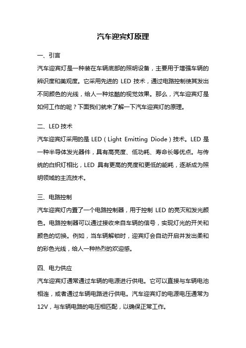
汽车迎宾灯原理一、引言汽车迎宾灯是一种装在车辆底部的照明设备,主要用于增强车辆的辨识度和美观度。
它采用先进的LED技术,通过电路控制使其发出不同颜色的光线,给人一种炫酷的视觉效果。
那么,汽车迎宾灯是如何工作的呢?下面我们就来了解一下汽车迎宾灯的原理。
二、LED技术汽车迎宾灯采用的是LED(Light Emitting Diode)技术。
LED是一种半导体发光器件,具有高亮度、低功耗、寿命长等优点。
与传统的白炽灯相比,LED具有更高的亮度和更低的能耗,逐渐成为照明领域的主流技术。
三、电路控制汽车迎宾灯内置了一个电路控制器,用于控制LED的亮灭和发光颜色。
电路控制器可以通过接收来自车辆的信号,实现灯光的开关和颜色的切换。
例如,当车辆解锁时,迎宾灯会自动开启并发出柔和的彩色光线,给人一种热烈的欢迎感。
四、电力供应汽车迎宾灯通常通过车辆的电源进行供电。
它可以直接与车辆电池相连,或者通过车辆电路进行供电。
汽车迎宾灯的电源电压通常为12V,与车辆电路的电压相匹配,以确保正常工作。
五、工作原理当汽车迎宾灯接收到开关信号后,电路控制器会将电能传递给LED。
LED内部有两个半导体材料,即P型半导体和N型半导体。
当电流通过LED时,P型半导体和N型半导体之间的结合面发生能级反转,从而使得电子和空穴重新组合,释放出光子,产生可见光。
六、发光颜色汽车迎宾灯可以发出多种颜色的光线,如红色、绿色、蓝色等。
这是通过在LED内部添加不同的发光材料来实现的。
例如,向LED中添加红色发光材料,就可以使其发出红色光线。
通过电路控制器的调节,可以实现不同颜色的切换和组合,呈现出丰富多彩的光效。
七、安装位置汽车迎宾灯通常安装在车辆底部的门槛板上。
这个位置既可以增加车辆的辨识度,又可以保护迎宾灯不受外部碰撞和损坏。
安装时,需要将迎宾灯固定在门槛板上,并正确连接到车辆的电源。
八、应用场景汽车迎宾灯主要应用于豪华车型和改装车辆中。
它不仅可以提升车辆的豪华感和科技感,还可以在夜间行驶时提供一定的照明效果,增加行车安全性。
NORSOK_L-005 (译文)
NORSOK标准L-005第2版,2006年5月紧凑型法兰连接挪威石油标准化组织规范(以下简称NORSOK标准)由挪威石油工业领域相关方经广泛参与制定,所有权归代表挪威石油工业的OLF(挪威石油工业协会)和挪威工业联合会。
请注意所有的努力都是为了确保本NORSOK标准的准确性,无论是OLF,还是挪威工业联合会或其任何成员,都不承担任何因应用本标准而产生的相关责任。
本NORSOK标准由挪威标准化管理和发行。
挪威标准化机构电话:+4767838600挪威传真+4767838601Lysaker市1326号电子邮箱:petroleum@standard.noStrandveien18号242信箱网址:www.standard.no/petroleum版权所有前言2简介21范围4 2参考标准和资料42.1参考标准42.2参考资料4 3术语、定义和缩略语53.1定义53.2缩略语64基本设计要求64.1概述64.2材料74.3强度74.4抗腐蚀性84.5温度84.6泄漏84.7供应商特定CFC的信息要求84.8型号和标记85产品标准95.1概述95.2第5条中所采用的参考标准95.3法兰设计和特征的总体说明105.4标准组件115.5型号135.6一般要求135.7尺寸145.8法兰重量145.9法兰表面155.10表面加工155.11容差165.12标记165.13IX型密封圈165.14搬运、安装及组装18附录A(规范性)法兰尺寸和重量27附录B(规范性)密封件尺寸和重量59附录C(规范性)螺栓尺寸和重量64附录D(规范性)压力温度等级70附录E(资料性)材料72附录F(资料性)公制螺栓74附录G(资料性)规定事项说明76附录H(规范性)整体法兰角的选择77参考文献86前言本NORSOK标准由挪威石油工业制定,以确保挪威石油工业的发展和运行足够安全、增值(附加价值)和资金的有效使用。
此外,本标准尽可能在更广的范围内代替石油公司的技术规范,并作为官方规章之用。
别克 GL8ESAvenir配置表
s s s s s s s s s s s s(6个USB) s s s s s s s s s s s s s
Avenir艾维亚 四座尊礼版
18吋皇冠型抛光铝合金轮毂
815
s
s s s s s s s s s s s s s s s
s s s s s s s s s s s s s s s s s
521/851 70
2.0T可变缸涡轮增压发动机,带发动机启停功能 1998
174/5000 350/1500~4000 9速HYDRA-MATIC智能变速箱
195 9.8 符合国六B排放标准/95号或以上无铅汽油 6.6 7.9 增强型麦弗逊悬挂/多连杆独立悬挂 EPS电子随速助力转向系统 FNC专利技术前通风盘式/后盘式,带制动盘清洁功能 博世iBooster电控制动助力器
s s s s s s s s s(第二排) s s s s s s s s s s s s s s
s s s s s s s s s(第二/三排) s s s s s s s s s s s s s s
s
s
s
s
s
s
s
s
s
s
s
s
s
s
s
s
s
s
s
s
s
s
s
s
s
s
s
s
s
s
s
s
s
s
s s s s s s s s s s s s(6个USB) s s s s s s s s s s s s s
iBuick APP手机应用(包括安吉星功能)
外观配置 Matrix矩阵式全LED晶钻大灯 展翼型LED日间行车灯 LED流光转向灯 展翼型全LED晶石尾灯带羽纹光幕 智能动态礼宾灯功能 飞翼式扰流板带LED高位刹车灯 外后视镜电动调节/加热/LED转向灯 外后视镜电动折叠/锁车自动折叠/驾驶侧防眩目 超大全景双天窗 后窗及后挡风防紫外线隐私玻璃 一体式车顶镀铬饰条 环绕式车身镀铬饰条 对置式门把手 鲨鱼鳍综合信号接收天线 艾维亚专属立体网状镀铬进气格栅 艾维亚专属Avenir字样车标 艾维亚专属Avenir字样银翼迎宾光毯 内饰配置 四幅多功能真皮方向盘带换挡拨片 前排豪华分层式中央储物箱 前排座椅后背储物袋 第二排座椅后背储物袋 后排乘客上车扶手 全LED顶衬照明 后排天窗全遮光电动遮阳帘 艾维亚专属立体菱格纹内饰面板 艾维亚专属高级麂皮绒面顶衬 艾维亚专属128色环境氛围照明系统 艾维亚专属居家级长绒地毯 艾维亚专属Avenir字样照明迎宾踏板 艾维亚专属Avenir字样高级定制头枕 “低调之风”车上精品四件套 “低调之风”车上香氛 座椅配置 驾驶座椅12向电动调节带腰托 副驾驶座椅6向电动调节 前排座椅头枕4向调节 前排可调节扶手 前排座椅加热/通风功能 第二排豪华贵宾座椅 -超长前后滑动功能 -加热/通风/按摩功能 -6向调节头枕 -电动椅背调节/电动腿托调节/4向电动腰托 -老板键(可调节副驾驶位置) -豪华翻折小桌板 第三排6:4分割可倒式座椅带中央扶手 第三排豪华贵宾座椅 -前后滑动/椅背调节 -加热/通风功能 -独立可调节扶手 第二排豪华头等舱座椅 -加热/腿托加热/通风/十点式按摩功能 -电动椅背/电动腿托/4向电动腰托 -电动调节三体式头枕 -座椅全倾倒及一键复位功能 -座椅独立调节触控屏 -无线充电面板 -游艇式扶手私密储物空间 艾维亚专属象牙白打孔真皮座椅 艾维亚专属黛蓝月白镶拼Nappa高级打孔真皮座椅 安全配置 BFI一体化车身结构 前排双预紧式安全带 全车三点式安全带 第一、二排安全带未系提醒 前排正面安全气囊 前排侧面安全气囊 一体式侧安全气帘 前排膝部安全气囊 儿童座椅ISO FIX固定器 四门自动落锁系统 博世ESP电子稳定控制系统 ABS防抱死制动系统 EBD电子制动力分配系统 TCS牵引力控制系统 HSA坡道辅助系统 HDC陡坡缓降系统 TPMS智能胎压监测系统 EPB电子驻车制动系统 Autohold自动驻车系统 驻车雷达(前6后6) 高清360°全景泊车影像 电子防眩目内后视镜 高清流媒体内后视镜 高级智能驾驶辅助 LCC车道居中智能巡航系统 TJA交通拥堵辅助系统 HOD方向盘离手检测功能 ESS紧急安全停车 ADB防眩目远光功能 ACC自适应巡航系统 SBZA侧盲区预警系统 LCA车道变更辅助系统 LKA车道保持系统 LDW车道偏离预警 FDI前车距离提示 FCA前方碰撞预警系统 CMB碰撞缓解系统 RCTA泊车预警系统 APA自动泊车系统 PD行人识别 DOW开门安全预警系统 舒适装配 智能防夹双侧电动滑移门 四门无钥匙进入及一键启动 发动机远程启动 中控门锁及遥控钥匙 四门车窗一键式自动升降(带防夹)功能 雨量感应间歇式无骨雨刷 后挡风玻璃无骨雨刷 后挡风玻璃热线式除雾功能 大灯伴你回家功能 双12.3吋仪表及中控联屏 HUD全彩平视显示系统 多音源输入(USB/SD/蓝牙) AVL随速音量调节系统 蓝牙免提电话 高保真立体声收音机 Bose Centerpoint®环绕声音响系统带12扬声器 三区独立全自动空调系统 二/三排顶置空调出风口 双效纳米级防PM2.5空调滤芯 车内负离子空气净化系统 AQS空气质量控制系统 触摸式空调及车辆控制面板 后排独立控制触摸式空调面板 230V电源输出 带腿部感应的电动高度可调举升门
- 1、下载文档前请自行甄别文档内容的完整性,平台不提供额外的编辑、内容补充、找答案等附加服务。
- 2、"仅部分预览"的文档,不可在线预览部分如存在完整性等问题,可反馈申请退款(可完整预览的文档不适用该条件!)。
- 3、如文档侵犯您的权益,请联系客服反馈,我们会尽快为您处理(人工客服工作时间:9:00-18:30)。
□□□□
4、 要特别招呼小朋友,行动不便及年长或怀孕的顾客。
□□□□
5、 对迟到、早到,晚到的顾客都要亲切妥善的应对。
□□□□
6、 对在外面参考菜单,犹豫不决的顾客,主动争取上门消费的机会。
□□□□
7、 对订位但已迟到的顾客主动联络,了解状况,妥善服务。
□□□□
8、 随时保持门口,候位区域的整洁。
□□□□
稍坐一下。
【情形2-2】不能确认准确时间(没有客人离席)
【动作流程】: 指引客人至候位区候坐,并立即提供候位服务。
□□□□
【服务用语】: 真的很抱歉!XX先生(小姐),您先稍坐一下,给我点时间,我会第一时间 □□□□
【服务用语】: 为您准备位子。
【情形3】无订位,有位子
【动作流程1】: 询问顾客之用餐人数及是否抽烟,并为客人安排适当座位并交接给带位。 □□□□
【服务用语】: 提前电话订位,希望下次有机会为您服务。
【情形5】有订位,迟到,现场有位
【动作流程】: 请参照【情形1】“有订位,有位子”的流程
□□□□
【情形6】有订位,迟到,现场无位
【动作流程】: 请参照【情形2】“有订位,无位子”的流程
□□□□
【情形7】订位,无资料
【动作流程】: 立刻记录顾客的资料,尽快为客人安排座位(尽量勿让客人发现)
【服务用语1-1】:请问先生(小姐)贵姓?
□□□□
【服务用语1-2】:请问先生(小姐),今天几位用餐呢?
□□□□
【服务用语1-3】:请问抽不抽烟?
□□□□
【动作流程2】: 向带位同仁交接桌号,并安排其带客人入座。
□□□□
【情形4】无订位,无位子
【动作流程】: 告之客人暂无位子提供,需候位。
□□□□
【服务用语】: 先生(小姐)您好,真的很抱歉,目前我们的座位都已经坐满,是否需要 □□□□
□□□□
【服务用语】: a.现场有位—比照有订有位
□□□□
【服务用语】 b.现场无位—比照有订无位
□□□□
《送客时》
1、 如有客人亲自至柜台买单时,引导并协助顾客结帐。﹝双手接帐单,并带至柜台前) □□□□
2、 适当的与顾客寒暄。
□□□□
3、 谢谢光临,拜拜!
□□□□
4、 为顾客开门或按电梯。
□□□□
领台工作站评分表【L005】
评
分
项
目
解示试回 说范做馈一、源自型与内心1、 端正的服装仪容(完全符合公司规定)
□□□□
2、 情绪稳定,保持愉快的心情
□□□□
3、 亲切大方、动作利落,随时随地贴心照顾顾客(亲切、大方、躬身、微笑)
□□□□
二、动作流程 《迎客时》
【动作流程 】: 为顾客开门或按电梯,并热忱的招呼
□□□□
【服务用语1】:“Hi,欢迎光临TASTy!”
□□□□
【服务用语2】: 请问有为您做过订位服务吗?
□□□□
【情形1】有订位,有位子
【动作流程1】: 从订位表上找到顾客订位后,再次向顾客确认其订位姓名,人数及用餐时间。 □□□□
【动作流程2】: 向带位同仁交接顾客姓氏,并安排同仁带客入座。
□□□□
【服务用语】: 先为您排号等位呢?
【情形4-1】客人愿意候位时
● 未使用候位单时
【动作流程】: 询问顾客姓氏、用餐人数及是否抽烟,并登记于订位表上。 引导至候位区 □□□□
【动作流程】: 候位,并立即提供候位服务。
【服务用语1】: 请问先生(小姐)您贵姓,几位用餐?
□□□□
【服务用语2】: 请问抽不抽烟?
□□□□
优缺
领台工作站评分表【L005】
评
分
项
目
解示试回 优 说范做馈
【服务用语3】: X先生(小姐),这是你的候位单,您排的是XX号,现在是XX号, 请您稍候 □□□□
一下并留意叫号,以免跳号重排,我们会尽快为您安排。
【情形4-2】客人不愿意候位时
【动作流程】: 致上歉意,送上店卡。
□□□□
【服务用语】: 真的很抱歉,这是我们的店卡,上面有我们的订位电话,您下次来时可以 □□□□
□□□□
2、 与带位保持良好的默契。
□□□□
3、 与柜台保持良好的默契。
□□□□
4、 与菜口保持良好的默契。
□□□□
5、 与区控保持良好的默契。
□□□□
五、注意事项
1、 与顾客互动时,目光都要注视着顾客且面带微笑。
□□□□
2、 有效的控制餐桌的周转率。
□□□□
3、 要留住候位的顾客或争取下次再来的机会,善用名片或店卡。
三、敏感度
1、 顾客候位时,经常安抚顾客并适时提供候位服务。(如:候位饮料、菜单等)
□□□□
2、 顾客同时抵达时,对后到顾客要妥善招呼致意。
□□□□
3、 对顾客的意见、建议及抱怨要立即处理。
□□□□
4、 依情况适时向顾客回报候位进度。(目前的侯位情形、寒暄、安抚等)
□□□□
四、团队精神
1、 与值班保持良好的默契。
9、 依候位情况准备候位饮料、小点及候位单。
□□□□
10、 对于6人位以上(含6人)之订位,须于营业前再次确认订位状况。
□□□□
11、 对在安排座位时有抱怨的客人,在客人用餐过程中,再次向客人致歉。
□□□□
12、 针对公家机关来访或用餐,需立即通知店长。
□□□□
13、 需主动为顾客开门按电梯。
□□□□
□□□□
【服务用语3】: 您先稍坐一下,我们会尽快为您安排。
□□□□
● 使用候位单时
【动作流程】: 询问顾客姓氏、用餐人数及是否抽烟,为客人发放候位单, 引导至候位区 □□□□
【动作流程】: 候位,并立即提供候位服务。
【服务用语1】: 请问先生(小姐)您贵姓,几位用餐?
□□□□
【服务用语2】: 请问抽不抽烟?
例:麻烦帮我接待陈先生6位A1
【情形2】有订位,无位子
【动作流程】: 向客人致歉,并提供候位服务。
□□□□
【情形2-1】在短时间内有位子(前桌客人已离席)
【动作流程】: 指引客人至候位区候坐,并立即提供候位服务。
□□□□
【服务用语】: 真的很抱歉!XX先生(小姐)您的座位正在整理中,大概需要XX分钟,请 □□□□