尚方SF-469B型温度控制器使用说明书
温控器说明书
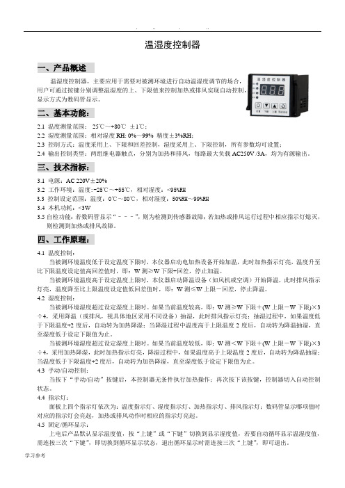
温湿度控制器一、产品概述温湿度控制器,主要应用于需要对被测环境进行自动温湿度调节的场合,用户可通过按键分别调整温湿度的上、下限值来控制加热或排风实现自动控制,显示方式为数码管显示。
二、基本功能:2.1 温度测量范围:-25℃~+80℃±1℃;2.2 湿度测量范围:相对湿度RH: 0%~99% 精度±3%RH;2.3 控制方式:温度采用上、下限和回差控制,湿度采用上、下限控制,所有参数均可设置;2.4 输出控制类型:两组继电器触点,分别为加热和排风,每路最大负载AC250V /3A,均为有源输出。
三、技术指标:3.1电源:AC 220V±20%3.2 工作环境:温度:-25℃~+55℃,相对湿度:<95%RH3.3控制设定范围:温度:0℃~80℃,相对湿度:50%RH~99%RH3.4 本机功耗:<3W3.5自检功能:若数码管显示“–––”,则为检测到传感器故障;若加热或排风运行过程中相应指示灯熄灭,则检测到加热或排风故障。
四、工作原理:4.1 温度控制:当被测环境温度低于设定温度下限时,本仪器启动电加热设备开始加温,此时加热指示灯亮,温度升至比下限温度设定值高回差值时,即:W测≥W下限+回差,停止加温。
当被测环境温度高于设定温度上限时,本仪器启动降温设备(如风机或空调)开始降温,此时排风指示灯亮,温度降至比上限温度设定值低回差值时,即:W测≤W上限-回差,停止降温。
4.2 湿度控制:当被测环境湿度超过设定湿度上限时。
如果当前温度较高,即:W测≥W下限+(W上限-W下限)×3÷4,采用降温(或排风,视具体地区采用不同设备)抽湿,此时排风指示灯亮;抽湿过程中,如果温度低于下限温度+2度后,自动转为加热降湿;当降湿过程中温度高于上限温度-2度后,自动转为降温抽湿,直至湿度低于设定下限值为止。
当被测环境湿度超过设定湿度上限时。
如果当前温度较低,即:W测<W下限+(W上限-W下限)×3÷4,采用加热降湿,此时加热指示灯亮,降湿过程中,如果温度高于上限温度-2度后,自动转为降温抽湿;当温度低于下限温度+2度后,自动转为加热降湿,直至湿度低于设定下限值为止。
温度控制器安装和使用说明书
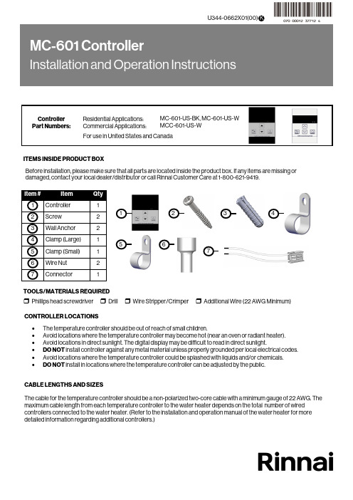
CONTROLLER LOCATIONS ∙ The temperature controller should be out of reach of small children.∙ Avoid locations where the temperature controller may become hot (near an oven or radiant heater). ∙ Avoid locations in direct sunlight. The digital display may be difficult to read in direct sunlight.∙ DO NOT install controller against any metal material unless properly grounded per local electrical codes. ∙ Avoid locations where the temperature controller could be splashed with liquids and/or chemicals. ∙DO NOT install in locations where the temperature controller can be adjusted by the public.CABLE LENGTHS AND SIZESThe cable for the temperature controller should be a non-polarized two-core cable with a minimum gauge of 22 AWG. The maximum cable length from each temperature controller to the water heater depends on the total number of wired controllers connected to the water heater. (Refer to the installation and operation manual of the water heater for moredetailed information regarding additional controllers.)Before installation, please make sure that all parts are located inside the product box. If any items are missing or damaged, contact your local dealer/distributor or call Rinnai Customer Care at 1-800-621-9419.123ITEMS INSIDE PRODUCT BOXTOOLS/MATERIALS REQUIRED456❒ Phillips head screwdriver ❒ Drill ❒ Wire Stripper/Crimper ❒ Additional Wire (22 AWG Minimum)71.Make 3 holes in the wall as shown below. (Reference template on last page.)2. Remove the face plate from the temperature controller using a screwdriver.When performing the steps in this section, you must follow the wiring guidelines established by the National Disconnect power to the water heater. Do not attempt to connect the temperature controller(s) with the power on.WARNING3. After disconnecting power to the water heater, connect the field-supplied wire to the stripped wire ends of the con-troller . Follow the wiring guidelines established by the National Electrical Code (NEC).4. Using the provided screws and wall anchors, mount the controller to the wall.5. Remove the protective film from the controller.Number of Controllers Maximum Cable Length for Each Controller toWater Heater1 328 ft. (100 m)2 164 ft. (50 m)3 or 465 ft. (20 m)Controllers wired in seriesControllers wired in parallelControllers canonly be wired in parallel; theycannot be wired inseries.FilmCover Plates3.31 i n . (84m m )1.65 i n . (42m m )1.Remove the front panel of the water heater.2. Locate the terminals for control in the water heater.3. Thread the cable through the base of the water heater4. Connect controller wires to the terminals for control.For additional information regarding installation and/or operation of the temperature controller, please refer to the Installation and Operation Manual of the water heater. 1.If the water heater is off, press the “On/Off” button to turn on.2. The “Priority” button enables a controller if multiple controllers are being used. If the “Priority” light is off, then press the“Priority” button on the temperature controller. The green “Priority” light will glow indicating that this controller iscontrolling the temperature and that the water heater is ready to supply hot water. The priority can only be changed while no hot water is running. 3. Press the (Up) or (Down) buttons to obtain the desired temperature setting. All hot water sources are able toprovide water at this temperature setting until it is changed again at this or another temperature controller. 4. To operate the water heater, open any hot water fixture. The water heater will then activate and the water heater “In Use”indicator will illuminate on the controller show that the water heater is providing hot water. For further information on controller operation, refer to the installation and operation manual of the water heater.Enables controller when multiplecontrollers are usedDisplayDecreases hot water temperatureIncreases hot water temperatureTurns the water heater on or off“In Use” IndicatorInstalling Four Controllers 1.If 4 MC-601’s are installed, press the “Priority ” and “On/Off ” buttons on the fourth controller at the same time until a beep sounds. (See above)2. Check that the displays on all four controllers are lit and displaying the temperature setting when switched on. If any ofthe controllers displays two dashes then repeat step 1. Note: If a controller is replaced, repeat these steps for the replacement controller.In applications where a Rinnai Control-R™ module is installed in place of a 4th controller and there is: ∙ Option 1 in Rinnai Control-R™ mobile app - “No Recirculation” - Perform Step 1 above.∙ Option 2 in Rinnai Control-R™ mobile app - “Recirculation” - Step 1 above is not necessary.HOTBURNSecuring Screw Securing Screw Wiring Hole Overall Controller Dimension: ∙ W: 3.54 in. ∙ H: 4.72 in. ∙D: 0.70 in.Ø.20Ø.50Ø.20100000570(02)9/2022。
温控仪操作说明

1.手动/自动无扰动切换按A/M键,MAN指示灯亮,进入手动状态。
当前SV显示器数值即为输出百分比,PV 显示器为测量值。
用“向左”、“向上”和“向下”键可手动修改输出百分比。
再按A/M 键,MAN指示灯熄灭,仪表进入自动状态。
此时,SV显示原设定值,PV显示仍为测量值。
仪表在任何状态下均可进入手动/自动状态。
2.人工修改PID参数在LEVEL1下,按SET键5s进入LEVEL2,按SET键选择P、I和D参数选项即可进行设定。
3.室温显示修正热电偶分度号输入时,若输入端子短接,仪表显示值应近似为室温,若有较大差异,同时按下SET键和“向左”键,进入LEVEL3,然后按SET键数次,找到PVS选项,人工设定修正PVS值。
4.恒温定时报警设定需设定恒温报警时,先选择报警组别(AL1和AL2均可),并设定报警模式为9,然后对该组AL输入定时数值(单位为min)。
当PV=PS时,该组别报警灯亮(继电器无动作),并立刻开始计时(预设定时数值递减为0000),定时结束,报警继电器动作。
5.软启动预置斜率控制(选配)当系统需要软启动时(SV预置斜率升温),按如下顺序操作:设定好SV值→在LEVEL1下按SET键找到RAP选项,设定好温度→按SET键找到RTM选项,设定斜率时间(单位为min)。
例如要设斜率为10℃/min时,RAP设为10.0,RTM设为001.0即可。
设定完毕,软启动将会立即从当前的PV值按斜率升温,直到PV=SV为止。
若需暂停斜率升温,同时按下SET键和“向上”,SV数值可任意修改,进行定值控制。
若要取消软启动,输入0.0℃/min即可。
6.除湿功能(选配)需除湿时按如下顺序操作:在LEVEL3下,按SET键数次找到SRT选项,预置除湿工作时的输出百分比,可预置V=2.0-5.0(例如,SRT设为40℃,LMO设为2.0,即仪表开机时系统的温度低于40℃时,仪表以2%的功率输出,这样可避免烧坏加热器)。
温控器使用说明书
一周编程电子智能室内温控器LOGIC 578001使用指南引言感谢您选择了我们的产品及对我们的信任与支持。
本装置是电子式定时恒温器,可设置一星期为周期的运行程序。
通过该装置,可对安装环境内的温度进行十分精确的调节控制,满足用户对创造一个舒适生活环境的要求。
符合标准:符合欧盟法令:EN 60730-1 标准及其修订内容欧盟 B.T.73/23/EEC号法令EN 60730-2-7 标准欧盟 E.M.C.89/336/EEC号法令及93/68/EEC修改法令EN 60730-2-9 标准产品规格:电源:二节LR6型1.5V碱性电池温度调节范围:10至35℃显示屏显示之环境温度:0至40℃(分辩率0.1℃)温度修正频率:每分钟一次微分:0.2至0.4K探针传感器:NTC3%保护等级:IP20绝缘等级:热梯度:1K/15分输出:转换继电器触点容量:8(2.5)A250V~作用类型:1BU绝缘条件:正常环境最大工作温度:50℃储存温度:0-60℃防冻温度:6℃恒定运行程序:以一星期为周期设置软件等级:A液晶显示屏夏季/冬季(采暖/空调)切换程序设置中的最小增减允许时间:1小时安装:壁式安装安装及连接:安全预防措施在进行定时恒温器的连接之前,请确认受其控制的设备系统(采暖锅炉、泵和空调系统等)电源已断开,并需检查这些设备的使用电压是否与定时恒温器底座上表明的电压相符(最大250V~).(图4)安装位置定时恒温器须安装在远离热源(暖气装置、阳光、厨房)和门窗之处,安装高度离地面约1.5米。
(图5)安装见图6-7-8电气连接将受定时恒温器控制的设备系统电线与定时恒温器的1号及2号接线柱连接见接线图10所示U=受定时恒温器控制的设备1=共用接线柱2=常开接线柱3=常闭接线柱重要事项:请务必严格遵照相关现行法律的规定及安全规范安装定时恒温器。
电池更换:当在显示屏上闪烁显示“”标志时,定时恒温器还可正常工作约一个月左右,然后将会停止工作并固定显示“”。
温控仪的说明书
运行状态
0~2
设定为 1
Loc
参数密码锁
0~9999
密码设置,初始值 655
F1
现场参数 1
None~run
/
F2
现场参数 2
None~run
/
F3
现场参数 3
None~run
/
F4
现场参数 4
None~run
/
F5
现场参数 5
None~run
/
F6
现场参数 6
None~run
/
F7
现场参数 7
None~run
/
F8
现场参数 8
None~run
/
M5 为保持参数。定义为输出值变化 5%时,控制对象基本稳定后测量值与变化前测量值的差 值。同一系统的 M5 参数一般会随测量值有所变化,所以应取工作点附近为准。M5 参数值主要决 定调节算法中积分作用,和 PID 调节的积分时间类似。M5 值越小,系统积分作用越强。M5 值越 大,积分作用越弱。
85避免强腐蚀气体供电电源85265vac50hz60hz绝缘电阻100m500vdc电源输入输出与地之间功耗10w三仪表面板及操作说明1仪表面板说明out输出指示灯run手动运行状态指示灯pv测量值显示窗口sv设定值显示窗口设定键set移位键数据减少键数据增加键sp1报警指示灯sp2报警指示灯12仪表端子接线四输入信号方式及类型1配用标准热电偶热电阻分度号kswretejbnpt100cu50分辨率11111111101测量范围0130001600023002003500100001000600180001300200600150150配用传感器镍铬镍硅热电偶铂铑10铂热电偶钨铼325热电偶铜铜镍康铜镍铬铜镍热电偶铁铜镍康铜铂铑10铂铑6热电偶镍铬硅镍硅热电偶铂热电阻r0100铜热电阻r0502输入类型代码表in01234输入规格k2001300s501700wre02300t200350e01000in5672021输入规格j01000b01800n01300cu5050150pt1002006002五仪表使用和操作1测量状态仪表安装应进行正确接线检查无误后上电仪表自检后进入测量值显示状态