温度控制器 SF-104使用说明
多功能数显温度控制器安全操作及保养规程
多功能数显温度控制器安全操作及保养规程1. 引言多功能数显温度控制器是一种广泛应用于工业生产中的仪器设备,用于监测和控制温度。
为了确保设备的正常运行和延长使用寿命,用户需要严格遵守安全操作规程并进行定期保养。
本文将介绍多功能数显温度控制器的安全操作指南和保养规程。
2. 安全操作指南2.1 仪器安装•在安装多功能数显温度控制器之前,务必事先了解所需安装设备的参数要求和安装位置要求。
•安装多功能数显温度控制器时,应确保周围环境干燥、通风良好,远离易燃、易爆和腐蚀性物质。
•确保设备安装牢固,使用接地线连接设备,以保证设备的接地安全。
•在设备安装完成后,检查所有电缆连接是否牢固,避免松脱或短路。
2.2 电气安全•在进行任何维护或保养操作之前,务必确认设备已经断开电源并处于停机状态。
•使用标准电源插座,并确保配电线路符合国家电气标准。
•不要将多功能数显温度控制器连接到超过其额定电压或电流的电源。
•避免在多功能数显温度控制器和其他设备之间使用过长或损坏的电缆连接。
2.3 温度控制操作•在进行温度控制操作之前,仔细阅读并理解多功能数显温度控制器的操作说明书。
•切勿在设备处于运行状态下进行任何相关操作或维护工作,以免触电或受伤。
•根据生产环境和产品要求,合理设置温度控制参数,并检查温度传感器的准确性。
•定期检查设备的温度控制算法和输出功能,确保系统的稳定性和可靠性。
2.4 紧急处理•若发生任何紧急情况或异常状况,立即停止设备运行,并断开电源。
•寻找并消除故障源,避免更严重的事故发生。
•如遇到无法解决的问题,请及时联系设备供应商或专业维修服务人员。
3. 保养规程3.1 清洁与防尘•定期(每月或根据使用情况)对多功能数显温度控制器进行清洁,可使用干净的软布轻轻擦拭设备表面。
•避免使用含有酸碱物质的溶剂或刷子清洁设备,以免损坏表面涂层。
•定期检查设备的散热孔,确保通风良好,防止灰尘积累影响设备散热效果和正常运行。
3.2 保护设备•避免多功能数显温度控制器受到强烈撞击或震动,以免损坏设备内部零部件。
温控仪说明书
:加热器断线报警(CTL-6*3
D:
范围内报警
S
:加热器断线报警(CTL-12*3
E:
附待机上限偏差报警
R
:控制环断线报警*4
F:
附待机下限偏差报警
V
:上限设定值报警
G;
附待机上下限偏差报警
W
:下限设定值报警
⑦第一报警(ALM1,⑧第二报警(ALM2 *2
H:上限输入值报警
⑨通信功能(仅限CD系列)
设定模式 参数设定模式
4工程师参数设定模式
第4篇通讯篇(仅限CD系列表)
第5篇其它
第
1.型号定义
请参照下列代码表确认产品是否与您指定的型号一致。
CD/CH□01/02□ □ □-□ □*□ □-□ □
① ② ③ ④ ⑤ ⑥ ⑦ ⑧ ⑨ ⑩
①规格尺寸 详见第1篇节
②控制类型
F:PID动作及自动演算(逆动作)
⑺本系列仪器无电源开关和保险丝,如需可加装。
保险丝型号:延时保险
⑻当为电流输入时,必须在输入端子间接入250Q(土%±10ppm或
更大)的电阻,由客户自己解决。
⑼不要过分旋紧端子螺钉。请使用合适的端子螺丝接线片(螺丝型号M3X6建议
力矩[])。
4.规格
输入
种类:
a)热电偶:
K,J,R, S, B, E,T,N, U, L,PLH,W5Re/W26Re
•空调的直吹。
•室内使用,勿置于阳光直射下。
•热辐射积累之处。
3.
端子构成
接线注意事项
⑴热电偶输入,应使用对应的补偿导线。
⑵热电阻输入,应使用低电阻且无差别的3根导线。
⑶输入信号线应远离仪器电源线,动力电源线和负荷线以避免产生杂讯干扰。
温控器说明书
温湿度控制器一、产品概述温湿度控制器,主要应用于需要对被测环境进行自动温湿度调节的场合,用户可通过按键分别调整温湿度的上、下限值来控制加热或排风实现自动控制,显示方式为数码管显示。
二、基本功能:2.1 温度测量范围:-25℃~+80℃±1℃;2.2 湿度测量范围:相对湿度RH: 0%~99% 精度±3%RH;2.3 控制方式:温度采用上、下限和回差控制,湿度采用上、下限控制,所有参数均可设置;2.4 输出控制类型:两组继电器触点,分别为加热和排风,每路最大负载AC250V /3A,均为有源输出。
三、技术指标:3.1电源:AC 220V±20%3.2 工作环境:温度:-25℃~+55℃,相对湿度:<95%RH3.3控制设定范围:温度:0℃~80℃,相对湿度:50%RH~99%RH3.4 本机功耗:<3W3.5自检功能:若数码管显示“–––”,则为检测到传感器故障;若加热或排风运行过程中相应指示灯熄灭,则检测到加热或排风故障。
四、工作原理:4.1 温度控制:当被测环境温度低于设定温度下限时,本仪器启动电加热设备开始加温,此时加热指示灯亮,温度升至比下限温度设定值高回差值时,即:W测≥W下限+回差,停止加温。
当被测环境温度高于设定温度上限时,本仪器启动降温设备(如风机或空调)开始降温,此时排风指示灯亮,温度降至比上限温度设定值低回差值时,即:W测≤W上限-回差,停止降温。
4.2 湿度控制:当被测环境湿度超过设定湿度上限时。
如果当前温度较高,即:W测≥W下限+(W上限-W下限)×3÷4,采用降温(或排风,视具体地区采用不同设备)抽湿,此时排风指示灯亮;抽湿过程中,如果温度低于下限温度+2度后,自动转为加热降湿;当降湿过程中温度高于上限温度-2度后,自动转为降温抽湿,直至湿度低于设定下限值为止。
当被测环境湿度超过设定湿度上限时。
如果当前温度较低,即:W测<W下限+(W上限-W下限)×3÷4,采用加热降湿,此时加热指示灯亮,降湿过程中,如果温度高于上限温度-2度后,自动转为降温抽湿;当温度低于下限温度+2度后,自动转为加热降湿,直至湿度低于设定下限值为止。
testo104温度计说明书

4. 按 Min 灯亮起,最小值显示。
5. 按 仪器恢复到测量模式。
删除最大值/最小值 11
1-4 同“ 显示最大值/最小值” 1-4 步骤。 5 . 按下 至少 2 秒。
Max Min CLr 显示。最大值/最小值删除。 仪器恢复到测量模式。
10
维护与保养
1. 旋开电池盒后盖的螺丝。 2. 打开电池盒后盖 3. 装入电池(2×AAA)注意极 性 4. 关闭电池盒后盖 5. 旋紧螺丝
保持读数:按 读数被锁定,Hold 灯亮起。
重新测量:按 自动保持读数功能(AutoHold) 仪器处于自动保持读数功能模式下 Auto Hold 闪烁,如果 10 秒后,仪器达到最终值,读数 自动锁定,Auto Hold 灯亮起。 重新测量:按
10
9
配置仪器
设置测量模式 将仪器关机。 1. 打开设置模式:展开探针的同时按住 显示 Auto Hold 或 Hold 2. 选择 Auto Hold 或 Hold:按 配置完成 键进行切换。 键。
0449 0047
用来读取数据记录器 SD 卡 使用范围高于 -10 °C 的电池(块 AAA 微型电池 Alkali Mangan) 使用范围高于 -10 °C 的蓄电池(块 AAA 微型电池 Alkali Mangan) CD testo ComSoft Professional CD testo ComSoft CFR ISO 湿度校准测试认证、校准测试点 11.3%RH;50.0 %RH;75.3%RH;温 度为 +25°C/+77°F;每个通道/设备
11
问题与答案 11.1. 附件与配件
3
2
使用说明
请仔细通读本文档,在使用之前熟悉本产品。把说明书带在 身边,需要时及时查阅。
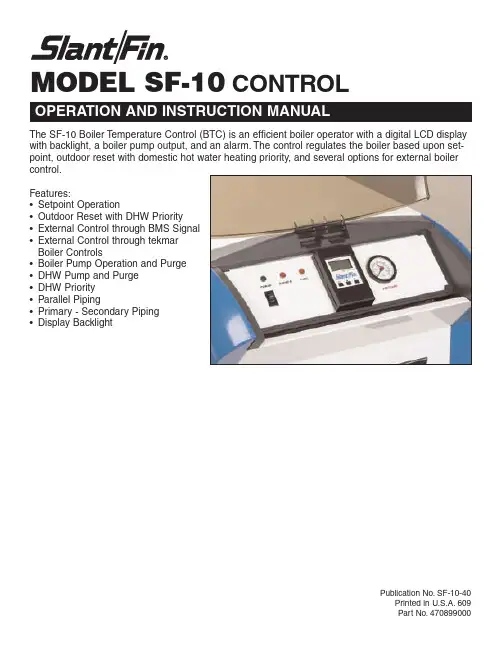
SF-10 水暖器温度控制器说明书
MODEL SF-10CONTROLPublication No.SF-10-40Printed in U.S.A.609Part No.470899000The SF-10 Boiler Temperature Control (BTC) is an efficient boiler operator with a digital LCD display with backlight, a boiler pump output, and an alarm.The control regulates the boiler based upon set-point, outdoor reset with domestic hot water heating priority, and several options for external boiler control.Features:•Setpoint Operation•Outdoor Reset with DHW Priority •External Control through BMS Signal •External Control through tekmar Boiler Controls•Boiler Pump Operation and Purge •DHW Pump and Purge •DHW Priority •Parallel Piping•Primary - Secondary Piping •Display BacklightT able of Contents ............................................................2User Interface ..................................................................2Display ............................................................................3Symbol Description ........................................................3Sequence of Operation .. (4)Section A:General ..............................................4Section B:Setpoint..............................................8Section C:Outdoor Reset....................................9Section D:External Temperature T arget............10Section E:External Direct Drive........................11Section F:Indirect Domestic Hot Water (11)Installation ....................................................................13Alarm Signal ................................................................14Testing ..........................................................................15Control (DIP Switch) Settings........................................17Mode 1 and 2 Setpoint & DHW OperationApplications........................................................18View Menu .. (19)Adjust Menu (20)Mode 3 and 4 Outdoor Reset & DHW OperationApplications........................................................21View Menu ........................................................22Adjust Menu ......................................................23Default Settings.. (23)Mode 5 and 6 External Target TemperatureApplications .......................................................25View Menu ........................................................26Adjust Menu (27)Mode 7 External Direct Drive OperationApplications........................................................29View Menu ........................................................29Adjust Menu (30)Reload Factory Defaults ................................................30Error Messages ............................................................31Technical Data .. (32)2The BTC uses a Liquid Crystal Display (LCD) as a method of supplying information.Y ou use the LCD in order to setup and monitor the operation of your system.The BTC uses three push buttons (Item , )for selecting and adjusting settings.As you program your control, record your settings in the settings column of the Adjust menu.The table is found in the second half of this brochure.MENUAll of the items displayed by the control are organized into two menus:1) View 2) AdjustT ITEMT ItemItemItem ItemItemItemSymbol Description4Model SF-10 Control Instructions ManualSequence of OperationSection A: GeneralSection AGeneral Operation Page 4 -8Section BSetpoint Operation Page 8Section COutdoor Reset Operation Page 9Section DExternal Temp. Target Input Page 10Section E External DirectDrive Operation Page 11Section FIndirect DHWOperation Page 11 - 12Boiler Outlet Sensor Boiler InletSensor BoilerSupply Sensor Boiler Outlet SensorBoilerInletSensorBTC Boiler Outlet Sensor DHW TankBoiler Inlet SensorPOWERING UP THE CONTROLWhen the control is powered up, the control turns on all segments in the display for 2 seconds.Next, the software version isdisplayed for 2 st, the control enters into the normal operating mode.DISPLA Y BACKLIGHT The control’sdisplay has a backlight that is permanently on while the control is powered.PIPINGThe boiler can be piped in parallel or in primary / secondary to the system.The type of piping chosen affects the location of the control’s operating temperature sensor.The control can either use the boiler outlet sensor or the boiler supply sensor.MODES 1(Setpoint and DHW Operation with Parallel Piping)Mode 1 is designed for setpoint and domestic hot water (DHW) opera-tion using parallel piping.Once a heat dem and signal is present, the control operates the boiler burner to maintain the boiler target at the boil-er outlet sensor.Refer to section B for a description of setpoint operation.Once a DHW demand is present, the control operates the boiler burner to m aintain the DHW target at the boiler outlet sensor.If both a heat demand and a DHW demand are present at the same time, the control targets the higher of the two requirem ents.Refer to section F for adescription of indirect domestic hot water operation.PARALLEL PIPING In parallel piping applications,the boiler outlet temperature is typically the same as that deliv-ered to the system.Therefore the operating temperature sensor is the boiler outlet sensor.PRIMARY / SECONDARY PIPINGIn primary /secondary applications,the boiler outlet tem perature (primary loop) istypically hotter than the system supply temperature (secondary loop).This occurs when the system supply pipe has a larger flow rate than the boiler outlet pipe.Therefore, the control requires an additional sensor (boiler supply) to measure the temperature delivered out to the system.The operating temperature sensor is the boiler supply sensor.MODES OF OPERATION (MODE)The control allows for seven modes of operation in order to define the control operation and piping arrangement used.The piping arrangement can be categorized into parallel and primary / secondary.The mode of operation is selected using the MODE item in the Adjust menu.The temperature being controlled out to the heating system is measured by the operating sensor.The piping arrangement determines which sensor the control uses as the operating sensor.The operating sensor is either the boil-er outlet sensor or the boiler supply sensor.BURNERDisplays when the stage 1 oWWSDDisplays when the control is Shut Down.Note:Stage 2contact is not useSection A GeneralOperationPage 4 -8Section BSetpoint Operation Page 8Section F Indirect DHWOperationPage 11 - 12Boiler Outlet SensorBoiler Inlet Sensor Boiler Supply SensorBoiler Outlet SensorBoilerInlet SensorBOILER PUMPDisplays when the boiler pump is in operation.HEAT DEMANDDisplays when a heat demand is present.DHW PUMPDisplays when the DHW pump is in operation.DHW DEMAND Displays when a DHW demand is present.BURNER Displays when the stage 1 or 2 contact is on.ERROR Displays when an error message is present.WWSDDisplays when the control is in Warm WeatherShut Down.POINTERSDisplays the operation as indicated by thtext.Note:Stage 2contact is not used in this application.Section A GeneralOperationPage 4 -8Section B Setpoint Operation Page 8Section C Outdoor Reset Operation Page 9Section DExternal Temp. Target Input Page 10Section EExternal Dire Drive OperatPage 11Section F Indirect DHW OperationPage 11 - 12Boiler Outlet SensorBoiler Inlet SensorBoiler Supply Sensor Boiler OutletSensor Boiler InletSensorBTCBoilerOutlet SensorDHW TankBoiler Inlet SensorMode 2 is designed for setpoint and domestic hot water (DHW) operationusing primary / secondary piping.Once a heat demand signal is present,the control operates the boiler burner to maintain the boiler target at theboiler supply sensor.Refer to section B for a description of setpointoperation.Once a DHW demand is present, the control operates the boiler burner tomaintain the DHW target at the boiler supply sensor.If both a heat demandand a DHW demand are present at the same time, the control targets thehigher of the two requirements.Refer to section F for a description of indi-rect domestic hot water operation.MODE 3(Outdoor Reset and DHW Operation with Parallel Piping)Mode 3 is designed for outdoor reset and dom estic hot water (DHW)operation using parallel piping.Once a heat dem and is present, thecontrol operates the boiler burner to maintain the calculated outdoor resettarget at the boiler outlet sensor.Refer to section C for a description ofoutdoor reset operation.Once a DHW demand is present, the control operates the boiler burner tomaintain the DHW target at the boiler outlet sensor.If both a heat demandand a DHW demand are present at the same time, the control targets thehigher of the two requirements.Refer to section F for a description of indi-rect domestic hot water operation.MODE 4(Outdoor Reset and DHW Operation with Primary/Secondary Piping)Mode 4 is designed for outdoor reset and dom estic hot water (DHW)operation using prim ary / secondary piping.Once a heat dem and ispresent, the control operates the boiler burner to maintain the calculatedoutdoor reset target at the boiler supply sensor.Refer to section C for adescription of outdoor reset operation.Once a DHW demand is present, the control operates the boiler burner tomaintain the DHW target at the boiler supply sensor.If both a heat demandand a DHW demand are present at the same time, the control targets thehigher of the two requirements.Refer to section F for a description of indi-rect domestic hot water operation.MODE 5(External Target Temperature Input and DHW Operation–Parallel Piping)Mode 5 is designed for an external input signal and domestic hot water(DHW) with parallel piping.The external input signal can be provided froma BMS, an EMS, or a tekm ar tN4 System Control.The external inputsignal creates an internal demand and changes the boiler target accord-ing to a linear scale.The control operates the boiler burner to maintain theboiler target at the boiler outlet sensor.Refer to section D for a descriptionof external target temperature operation.Once a DHW demand is present, the control operates the boiler burner tomaintain the DHW target at the boiler outlet sensor.If both a heat demandand a DHW dem and are present at the sam e tim e, the control targetsthe higher of the two requirem ents.Refer to section F for a descriptionof indirect domestic hot water operation.Model SF-10 Control Instructions Manual5STAGINGST AGE Model SF-10 Control Instructions Manual 7is viewed.sensor.BOILER PUMP OPERATION ( )The boiler pump contact operates when:•A heat dem and is present and parallel piping (Mode 1, 3, 5) is used.Parallel piping requires the boiler pum p to operate even while the burner is off in order to provide heat to the system.•While the burner is firing and primary / secondary piping (Mode 2, 4, 6) is used.Primary / secondary piping reduces standby losses by isolating the boiler from the system while the burner is off.•During external direct drive operation (mode 7), the boiler pump contact closes whenever there is a heat demand.•After the burner shuts off the boiler pump remains on to purge heat from the boiler to the system.•During a DHW dem and the boiler pum p contact is closed unless DHW priority is selected.During DHW priority, the boiler pump contact is off.BOILER PUMP PURGE ( DL Y)After the burner is shut off, the control continues to operate the boiler pump for a period of time.The length of time that the boiler pump continues to run is based on the Pump DL Y setting.Once the burner turns off, the control keeps the boiler pump running for the time selected.This setting allows purging of any excess heat out of the boiler after the boiler is shut off.This also helps to prevent the water in the boiler from flashing into steam after the boiler is shut off.When Pump DL Y is set to OFF, there is no purging.When Pump DL Y is set to ON, the pump runs continuously.When on is selected and the control is configured for outdoor reset, the pump continues to run even during Warm Weather Shut Down. EXERCISINGIf the boiler pump has not operated at least once every 70 hours, the control turns on the output for 10 seconds.This minimizes the possibility of the pump seizing during a long period of inactivity.When either m ode 1 or 2 is selected, the water tem perature is controlled based on a fixed setpoint.The setpoint temperature is set using the BOIL T ARGET item in the Adjust menu.HEAT DEMAND(Dem 1)A heat demand is required whenever heat is required for the setpoint load.A heat demand is generated when a voltage between 24 and 120 V (ac) is applied across the CD (common demand) and the Ht D (heat demand).Once voltage is applied, the control turns on the Dem 1 segment in the display.The control closes the pump contacts, which starts the boil-er pump and the control turns on the boiler pump segment in the display.If the operating sensor is 1/2 of the differential below the BOIL T ARGET, the control then closes the Stage 1 contact.The boiler target temperature is set using the BOIL T ARGET item in the Adjust menu.If the operating sensor reaches 1/2 of the differential above the BOIL T ARGET setting, the boiler burner is shut off.The pump contact remains closed until the heat demand is removed and Pump DL Y setting expires.8Model SF-10 Control Instructions ManualModel SF-10 Control Instructions Manual910Model SF-10 Control Instructions ManualWhen mode 7 is selected, the control allows for an external control to operate the boiler through an analog direct drive input signal provided by a boiler sequencing control such as a tekmar Boiler Control 265.When in mode 7, the external heat demand (CD and Ht D) and the DHW demand (CD and DHW D are disabled.DIRECT DRIVE INPUT SIGNALAn external boiler sequencer provides a positive 0-10 V (dc) input signal to the control +V(in) input (pin 10).The negative V (dc) signal is applied to the Com/- input.The boiler burner remains off while the direct drive input signal range is between 0 to 0.5 V (dc).The Stage 1 contact remains on as long as the direct drive input signal is over 0.5 V (dc).PUMP OPERATIONThe pump contact close as soon as the direct drive input signal reaches 0.5 V (dc).Once the direct drive inputsignal falls below 0.5 V (dc), the pump continues to operate until the Pump DL Y purge expires, then the pump shuts off.BOILER MAXIMUM TEMPERATUREThe external boiler sequencer is able to operate the boiler tem perature.However, the BOIL MAX setting lim its the highest temperature at the boiler outlet sensor.Should the boiler outlet temperature exceed the BOIL MAX setting, the Stage contact is opened to shut off the burner.The burner remains off for the minimum off time and the boiler outlet temperature falls 2°F (1°C)below the BOIL MAX setting.When modes 1, 2, 3, 4, 5, or 6 are selected, the control is able to override the heat demand operation and respond to heat an indirect domestic hot water (DHW) tank.DHW DEMAND (Dem 2)A DHW demand is required whenever the indirect DHW tank requires heating.A DHW demand is generated when a voltage between 24 and 120 V (ac) is applied across the CD (com m on dem and) and the DHW D (DHW dem and).Once voltage is applied, the control turns on the Dem 2 segment in the display.The control closes the DHW pump contacts, which starts the DHW pump and the control turns on the DHW pump segment in the display.BOILER TARGET DURING DHW OPERATIONThe boiler target temperature is at least as hot as the DHW BOIL T ARGET setting.If a heat demand is present during a DHW demand, the boiler target is the higher of the two temperatures.DHW OPERATION WITH PRIMARY / SECONDARY PIPINGWhen the boiler is piped in primary /secondary to the boiler and MODE is set to 2, 4, or 6, the control operates the boiler pump together with the DHW pump.ΩIt is often desirable to have priority for the DHW tank.is achieved by lim5.•When DHW MODE is set to 1 there is no DHW priority.•When DHW MODE is set to 2 there is DHW priority.DHW FULL & CONDITIONAL PRIORITYThe control provides full DHW priority when BOIL MIN is set to OFF.This is intended for use with condensing boilers. The control provides conditional DHW priority when BOIL MIN is not set to OFF.Should the DHW and the heat demand Array space heating occurs.to the OUT STthe OUT STDHW POST PURGEAfter the DHW Demand is removed, the control performs a purge on the boiler.In MODE 1, 3, or 5 (parallel piping), the control shuts off the burner and continues to operate the DHW pump.In MODE 2, 4, or 6 (primary / secondary piping), the control shuts off the burner and continues to operate the DHW pump while the boiler pump is turned on.This purges the residual heat from the boiler into the DHW tank.The control continues this purge for a maximum of two minutes or until the boiler supply water temperature drops 20°F (11°C) below the boiler target temperature during the DHW operation.The con-trol also stops the purge if the operating sensor temperature is close to the current boiler target temperature.DHW MIXING PURGEAfter DHW priority, the space heating zones m ay have cooled off considerably after being off for a period of tim e; meanwhile, the boiler is hot.To avoid thermally shocking the boiler after DHW priority, the control shuts off the burner, but continues to operate the DHW pump while restarting the boiler pump.This allows some of the DHW tank return water to mix with the cool return water from the zones and temper the boiler return water.12Model SF-10 Control Instructions ManualPowered Input Connections24 V(ac) PowerConnect the 24 V(ac) power supply to the C and R pins.This connec-tion provides power to the microprocessor and display of the control.Aswell, this connection provides power to the Alarm pin from the R pin.Heat DemandT o generate a heat demand, a voltage between 24 V (ac) and 120 V(ac) must be applied across the CD (common demand) and the Ht D(heat demand) pins.DHW DemandT o generate a DHW demand, a voltage between 24 V (ac) and 120 V(ac) must be applied across the CD (common demand) and the DHWD(DHW demand) pins.Caution:The same power supply must be used for both the heatdemand and DHW demand circuits since they share the CD (com-mon demand) pin.Output ConnectionsBoiler Pump ContactThe Pump pins are an isolated output in the control.There is no poweravailable on these pins from the control.This output is to be used as aswitch to either make or break power to the boiler pump.Since this isan isolated contact, it may switch a voltage between 24 V (ac) and 120V(ac).Model SF-10 Control Instructions Manual13Note:Note:An14Model SF-10 Control Instructions ManualExternal InputThe control can accept an external input signal from an external control.If an external input signal is required, connect the positive 0-10 V (dc) wire to the +V(in) pin and connect the negative 0-10 V (dc) wire to the Com/-.R 2216Model SF-10 Control Instructions ManualApply power to the control. the brochure.Model SF-10 Control Instructions Manual17MODE1 and 2 – Setpoint & DHW Operation MODE1 SETPOINT & DHW OPERATION – PARALLEL PIPINGModel SF-10 Control Instructions Manual 19MODE1 and 2 – Setpoint & DHW Operation20Model SF-10 Control Instructions ManualMODE3 and 4 – Outdoor Reset & DHW Operation MODE 3 – OUTDOOR RESET AND DHW OPERATION WITH PARALLEL PIPINGThe control receives a heat demand provided from zone valve end switches or a switching relay end switch.The control22Model SF-10 Control Instructions ManualModel SF-10 Control Instructions Manual2324Model SF-10 Control Instructions ManualMODE5 and 6 – External Target TemperatureMODE 5 – EXTERNAL TARGET TEMPERATURE INPUT & DHW OPERATION-PARALLEL PIPING The control receives a heat demand provided via an external analog input signal from an EMS, BMS or tekmar tN4 system control.The external analog input signal is interpreted as a setpoint target temperature.The control turns on the boiler pump and operates the boiler to maintain the setpoint boiler target temperature at the boiler outlet sensor.The control receives a26Model SF-10 Control Instructions ManualModel SF-10 Control Instructions Manual2728Model SF-10 Control Instructions ManualMODE7 – External Direct Drive Operation MODE 7 – EXTERNAL DRIVE OPERATIONRELOAD FACTORY DEFAULTSTo reload FACTORY DEFAULT SETTINGS, press and hold the outside buttons (Item and Down) while powering the control up.This will reload the FACTORY DEFAULTS.30Model SF-10 Control Instructions ManualModel SF-10 Control Instructions Manual31SLANT/FIN CORPORATION,Greenvale,N.Y.11548 • Phone:(516) 484-2600 FAX:(516) 484-5921•Canada:Slant/Fin LTD/LTEE,Mississauga, Ontario。
温度控制仪的操作规程(3篇)
第1篇一、设备准备1. 确认温度控制仪已正确连接电源,且电源开关处于关闭状态。
2. 检查温度控制仪的传感器是否完好,并与被测物体正确连接。
3. 确认温度控制仪已安装并固定在稳定的位置,避免震动和倾斜。
二、操作步骤1. 开启温度控制仪电源,等待设备初始化。
2. 设置温度控制仪的温度设定值:a. 按下“设定”键,进入设定模式。
b. 使用“加”、“减”键调整温度设定值。
c. 确认设定值后,按下“确认”键,退出设定模式。
3. 设置温度控制仪的工作模式:a. 按下“模式”键,选择所需的工作模式(如:恒定温度、定时加热、定时冷却等)。
b. 使用“加”、“减”键调整工作模式。
c. 确认工作模式后,按下“确认”键,退出设定模式。
4. 检查温度控制仪的报警设置:a. 按下“报警”键,进入报警设置模式。
b. 使用“加”、“减”键调整报警温度。
c. 确认报警温度后,按下“确认”键,退出设定模式。
5. 启动温度控制仪:a. 确认所有设置完成后,按下“启动”键,开始工作。
b. 温度控制仪开始根据设定值进行温度控制。
6. 监控温度控制仪的工作状态:a. 观察温度控制仪显示屏,了解当前温度、设定温度、报警温度等信息。
b. 如有异常情况,及时调整设定值或停止工作。
三、注意事项1. 温度控制仪在运行过程中,禁止触碰传感器、加热器等部件,以免发生危险。
2. 在调整温度设定值时,请确保温度设定值在设备允许的工作范围内。
3. 温度控制仪运行时,禁止将其放置在易燃、易爆、腐蚀性等有害环境中。
4. 温度控制仪运行过程中,如需停止工作,请先关闭“启动”键,再关闭电源开关。
5. 定期检查温度控制仪的传感器、加热器等部件,确保设备正常运行。
6. 如发现设备故障,请立即停止使用,并联系专业人员进行维修。
四、维护保养1. 定期清洁温度控制仪的显示屏、按键等部件,保持设备整洁。
2. 定期检查温度控制仪的电源线、传感器线等连接线,确保连接牢固。
3. 按照设备说明书进行定期维护保养,确保设备正常运行。
士林_温控器操作手册
3
2 SD 系列介紹.............................................................................................
4
2.1 SDV/SDE 性能概要及規格..............................................................
34
11.2 SETA 說明 ..............................................................................................
34
11.3 警報動作說明 .......................................................................................... 35
18
7.3 設定警報 ........................................................................................
18
7.4 自動演算 (Auto tuning) ..................................................................
17
7 操作步驟說明
7.1 開機 ...............................................................................................
18
7.2 設定 SV ..........................................................................................
温控器使用说明
中央空调温度控制器使用说明屏幕显示图标:——制冷——制热——通风——风速低速——风速中速温控器面板按键:电源开关()模式转换键()时钟键( )风速选择键(温度设置键(▲▼)使用说明✍开/关机:按“”键一次开机,开机显示为当前工作模式,以及该模式下有效运行时间;再按一次“”键关机,同时关闭风机盘管、电动阀。
✍模式选择:开机状态下,按“”键进行工作模式切换。
液晶显示“”表示制冷,显示“”表示制热,显示“”表示通风,5秒钟后自动确认。
✍风速选择:开机状态下,按“”键选择风机风速(高)、(中)、(低)、(自动)档。
在“自动”模式下,风速自动换档。
即当室温与设置温度相差1℃时,自动选择低风速;当室温与设置温度相差2℃时,自动选择中风速;当室温与设置温度相差3℃时,自动选择高风速。
当室温达到设置温度时,关闭电动阀和风机。
✍设定温度:开机状态下,按“❑”键降低设置温度,按“☐”键升高设置温度,每按键一次设置温度变化1℃。
时钟与相关功能设置✍睡眠功能设置:按“ ”键,直至出现“00”符号,按下“▲”键启用睡眠功能,按下“▼”键取消睡眠功能。
✍调整星期:按“ ”键,直至出现“01”符号,按下“▲”或“▼”键调整星期。
✍调整日历:按“ ”键,直至出现“02”符号和“xx−yy”的“xx”或“yy”闪烁,按“▲”或“▼”键调整年份;按“ ”键,直至出现“03”符号和“xx−yy”的“xx”或“yy”闪烁,按“▲”或“▼”键调整月份和日期;按“ ”键,直至出现“04”符号和“xx−yy”的“xx”或“yy”闪烁,按“▲”或“▼”键调整小时和分钟。
✍定时开机设置:按“ ”键,直至出现“定时开机”符号,以及“xx−yy”的“xx”闪烁,按“▲”或“▼”键调整定时开机小时,按“ ”键,“yy”闪烁,按“▲”或“▼”键调整定时开机分钟,按“ ”键确认;若设置“xx−yy”为“00-00”则取消定时开机功能。
✍定时关机设置:按“ ”键,直至出现“定时关机”符号,以及“xx−yy”的“xx”闪烁,按“▲”或“▼”键调整定时关机小时,按“ ”键,“yy”闪烁,按“▲”或“▼”键调整定时关机分钟,按“ ”键确认;若设置“xx−yy”为“00-00”则取消定时关机功能。
温度控制器说明书
Siebe Group CompanyPatented PDSIO® Load DiagnosticsPDSIO® (Pulse Density SignalingInput/Output) is a patented innovation in the 2208e. When used in combination with the Eurotherm TE10S Solid State Contactor, the same wires from the 2208e that transmit the logic output to the SSC can be used to read back load faults, SSC status and load RMS on-current. SSC failure (open or short circuit) or load failure (fuse blown, heater open circuit,missing line voltage) alarms can bedetected, flash on the front panel andtrip alarm relays. Amperage informationcan be read, displayed, and alarmed.PDSIO® information is also available onserial communications. PDSIO® is notavailable on the Valve Positioner.AlarmsUp to four process alarms may be combinedto a single alarm output. Alarms may befull scale high or low, deviation, rate ofchange or PDSIO® load failure. Alarmsmay be latching or non-latching and willflash on the front panel. Blocking alarms,which only become enabled after firstentering a safe state, are also available.Digital CommunicationsEIA-485 2-wire, EIA-422 4-wire or EIA-232serial communications is optionally availablewith industry standard Modbus® orproprietary EI-Bisynch protocol.Load diagnostic using Pulse Density Signaling Input/Output (PDSIO®)2208e TECHNICAL SPECIFICATIONInputsGeneral Range±100mV and 0 to 10Vdc (auto ranging)Sample rate9Hz (110mS)Calibration accuracy0.25% of reading, ±1 LSD or ±1°C/FResolution<1µV for ±100mV range, <0.2mV for 10Vdc rangeLinearizaton accuracy<0.1% of readingInput filter 1.0 to 999.9secsZero offset User adjustable over the fully display rangeThermocouple Types Refer to Sensor inputs and display ranges tableCold junction compensation Automatic compensation typically >30 to 1 rejection of ambient temperature changeExternal references 32, 113 and 122°F (0, 45 and 50°C).Incorporates INSTANT ACCURACY™ cold junction sensing technology.RTD/PT100Type3-wire, Pt100 DIN43760Bulb current0.2mALead compensation No error for 22 ohms in all 3 leadsProcess Linear±100mV, 0 to 20mA or 0 to 10Vdc (configurable between limits)Digital Type Contact closureApplication Manual select, 2nd setpoint, keylock and setpoint rate limit enableMode 5 Smart Digital Input™ (SDI), only on Digital LA inputOutputsRelay Rating: 2-pin relay Min: 12V, 100mA dc Max: 2A, 264Vac resistiveRating: change-over, alarm relays Min: 6V, 1mA dc Max: 2A, 264Vac resistiveApplication Heating, cooling or alarmsLogic Rating18Vdc at 24mA (non-isolated)Application Heating, cooling or alarmsThe logic output is field configurable as a standard logic output, PDSIO® Mode 1 or PDSIO®Mode 2.PDSIO® Mode 1:Logic heating with load failure alarm (also called SSRx Load Doctor™)PDSIO® Mode 2: Logic heating with load/SSC failure alarm and load current display (also calledSSRx Enhanced Load Doctor™)Triac Rating1A, 30 to 264Vac resistiveApplication Heating or coolingAnalog Range Isolated 0 to 20mA (into 600Ωmax) or 0 to 10Vdc (configurable between limits)Application Heating or coolingCommunicationsDigital Transmission standard EIA-485 2-wire, EIA-422 4 wire or EIA-232 at 1200, 2400, 4800, 9600, 19,200 baud Protocols Modbus® or EI-BisynchPDSIO®Setpoint input Setpoint input from master PDSIO® controller, also called Smart Setpoint Transmission™ (SST) Control functionsControl Modes PID or PI with overshoot inhibition, PD, P only or On/OffApplication Heating and coolingAuto/manual Bumpless transferSetpoint rate limit0.01 to 99.99 degrees or display units per minuteCooling algorithms Linear; Water (non-linear); Fan (minimum on time), Oil, proportional onlyTuning One-shot tune Automatic calculation of PID and overshoot inhibition parametersAutomatic droop compensation Automatic calculation of manual reset value when using PD controlAlarms Types Full scale high or low. Deviation high, low, band or any new alarm.Modes Latching or non-latching. Normal or blocking actionUp to four process alarms can be combined onto a single outputGeneralDisplay Dual, 4 digit x 7 segment high intensity LEDDimensions and weight 1.89W x 3.78H x 4.06D in (48W x 96H x 103Dmm) 14.1oz (400g)Supply85 to 264Vac -15%, +10%. 48 to 62Hz. 10watts maxTemperature and RH Operating: 32 to 131°F (0 to 55°C), RH: 5 to 90% non-condensing. Storage: 14 to 158°F (-10 to 70°C)Panel sealing IP 65Electromagnetic compatibility Meets generic emissions standard EN50081-2 for industrial environmentsMeets general immunity requirements of EN50082-2(95) for industrial environmentsSafety standards EN61010, installation category 2 (voltage transients must not exceed 2.5kV)Atmospheres Electrically conductive pollution must be excluded from the cabinet in which this controller ismounted. This product is not suitable for use above 6,562ft (2000m) or in corrosive or explosiveatmospheres without further protection.3.78i n (96m m )OP1OP2SP2REMPanel cut-out3.62in x 1.77in (92mm x 45mm)-0.0+0.8。
温控说明书
温控器接线图POWER UP PROCEDURE启动程序Verify all electrical connections have been properly made before applying power to the instrument.If the instrument is being powered for the first time, it may be desirable to disconnect the controller output connections. The instrument will be into control following the power up sequence and the output(s) may turn ON. During power up, a self-test procedure is initiated during which all LED segments in the two front panel displays appear and all LED indicators are ON. When the self-test procedure is complete, the instrument reverts to normal operation如果仪器首次被驱动的,它可能要断开控制器输出连接。
仪器会进入控制启动序列和后输出)可能打开。
在启动期间,自测过程启动期间所有LED。
自测过程完成后,仪器返回正常的操作。
.Note: A delay of about 3 seconds, when power is first applied, will be seen before the displays light up注意:延迟约3秒,当电源是第一次应用,将见过显示点亮.3.1.2 KEYPAD OPERATIONAUTO/MANUAL KEYThis key is used to:1. Enter the Auto/Manual mode and vice versa.2. Used to activate the Auto Tune mode.3. Used to confirm a change in the Program mode.自动/手动键这把键是用来:1。