andritz靴压操作1
靴压的安装与换靴套说明及系统操作06

Maintenance instructions1 1.1 1.2 2 2.1 2.2 3 3.1GENERAL INFORMATION Maintenance while machine is running Maintenance while machine is off LUBRICATION Recommendation for greasing, operating and drive side. Recommendation for oil lubrication BELT ADJUSTMENT DURING PRODUCTION Belt adjustment to home position2 2 2 4 4 4 5 603.09.20081/6KU 255-80038-06 en1General informationTo ensure efficient function of the PrimePress X, the following maintenance instructions must be adhered to. Take note of the locally valid safety and accident prevention regulations. Maintenance work is to be carried out by qualified and trained personnel only. Observe the manufacturer's instructions when using cleaning agents and/or solvents. If applicable, use protective gloves and/or safety goggles. DANGER1.1Maintenance while machine is runningFor this kind of maintenance, no safety devices may be removed or rendered ineffective! Maintenance intervals: 8 hours DANGERCheck the oil levels in the units and gearboxes on the external displays. To prevent dirt from entering the hydraulic system, do not check oil levels by pulling out oil dipsticks or by removing plugs while the hydraulic system is running. If there is oil loss, establish the causes When filling the system with oil, please refer to the documentation "Filling the hydraulic/lubricating unit" 095.302/17 in Chapter 750 of the operating manual. Inspect the surfaces of the rolls for visible damage Check the current flow rates on the displays. The setting values are taken from the hydraulics diagram 255-80038-98in section 750 of this operating manual. Check the sealing of a) Units b) Rolls c) Lines d) Devices Check running machine parts if these cause noise (e.g. pumps, motors)1.2Maintenance while machine is offMaintenance intervals: Clean the machine 10,000 hours03.09.20082/6KU 255-80038-06 enThe maximum permitted water jet pressure for cleaning the machine is 5 bar. The minimum distance for the spray nozzle to the surface or the component to be cleaned should be no less than 100 mm. If necessary, exchange the oil filter sets When the oil needs to be changed (see Chapter 2.2), drain the oil and clean the tank with non-fraying rags. Do not use cotton waste Clean the dirt trap in the cooling water flow pipe to the heat exchanger, or replace if necessary Exchange the air filter or the air filter inserts if necessary. Clean the filters on the computer, control cabinets, ventilated units and replace them if necessary Check the couplings on the drives for wear Check the screw connections on the lines for leaks and condition Check the status of hose lines Replace hoses 6 years after the manufacturing date (the manufacturing date is marked on the hose). Check the fastenings of the devices for firm seating Check the fastenings of the components Tighten up loose connections. After the maintenance tasks have been completed, re-install all barriers, panels and safety equipment that have been removed to perform the maintenance. Open the stop valves that had been closed during maintenance. Inspect all functions of the machine and of the safety devices. Only then may the machine be operated again.03.09.20083/6KU 255-80038-06 en22.1LubricationRecommendation for greasing,operating and drive side.Self-aligning bushing of the PrimeRoll X lubricating nipple 1.1 Lubricating grease MOBILGREASE XHP 222 Intermittent lubrication: 20 g Interval 6 months Self-aligning bushing of the PrimeRoll HV Smart, lubricating nipple 1.2 Lubricating grease MOBILGREASE XHP 222 Intermittent lubrication: 20 g Interval 6 months 1.2 1.12.2Recommendation for oil lubricationHave the oil checked by the manufacturer every third month. Whether the oil needs to be changed depends on the result of the oil inspection and the resulting recommendation of the manufacturer.Hydraulic unit for PrimePress X Hydraulic oil Oil quantity MOBILGEAR 600 XP 150 18000 litre (+ 1000 litre in reserve)03.09.20084/6KU 255-80038-06 en3Belt adjustment during productionTo achieve the maximal belt life 2.2, the belt has to be set off in its axial position towards the counter roll 2.6 in regular intervals. The belt adjustment can be done during production. Interval for adjusting the belt: approx. every 2 weeks by 10 mm towards the operating side. 2.4 2.1 2.2 2.32.52.6 a) Place a spanner on the turn journal 2.5 and adjust the stops 2.4 by 10 mm to the operating side (10 mm correspond to 1.5 revolutions).03.09.20085/6KU 255-80038-06 en3.1Belt adjustment to home positionOnce the stops 2.4 cannot be offset anymore after several adjustments, you need to move the belt 2.2 back into the home position. Danger of being crushed! During the adjustment of the belt there is a risk of crushing limbs between the moving border plate and the console. The roll drive is running a) On the process control system, select the function 'BELT ADJUSTMENT DRIVE SIDE'. Wait until the belt has moved automatically into the basic position of the drive side. b) Adjust the stops 2.4 as far as possible towards the operating-side border plate 2.3. To do so, use a spanner on the turn journal 2.5 to turn the stop 2.4 as far as possible towards the border plate on the operating side 2.3. c) On the process control system, select the function 'BELT ADJUSTMENT OPERATING SIDE'. The belt moves automatically to the stops 2.4.DANGER03.09.20086/6KU 255-80038-06 en。
安德里茨卫生纸机解决方案:高品质 低能耗
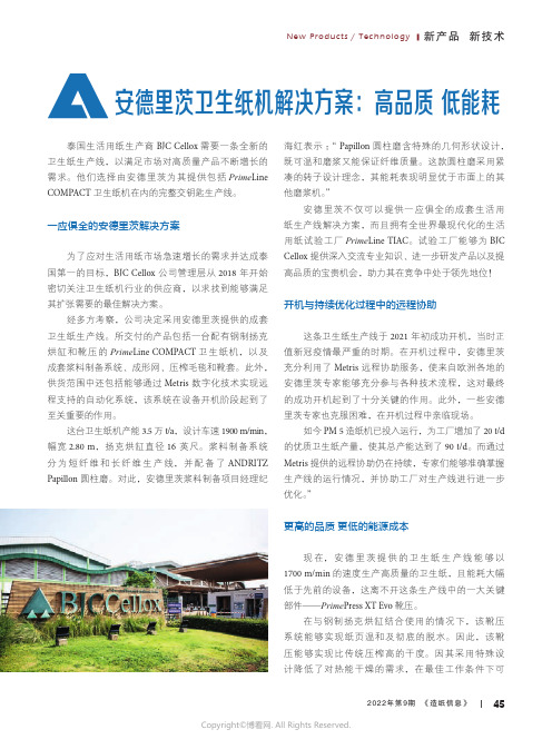
New Products / Technology ■ 新产品 新技术452022年第9期 《造纸信息》泰国生活用纸生产商 BJC Cellox 需要一条全新的卫生纸生产线,以满足市场对高质量产品不断增长的需求。
他们选择由安德里茨为其提供包括Prime Line COMPACT 卫生纸机在内的完整交钥匙生产线。
一应俱全的安德里茨解决方案为了应对生活用纸市场急速增长的需求并达成泰国第一的目标,BJC Cellox 公司管理层从 2018 年开始密切关注卫生纸机行业的供应商,以求找到能够满足其扩张需要的最佳解决方案。
经多方考察,公司决定采用安德里茨提供的成套卫生纸生产线。
所交付的产品包括一台配有钢制扬克烘缸和靴压的 Prime Line COMPACT 卫生纸机,以及成套浆料制备系统、成形网、压榨毛毯和靴套。
此外,供货范围中还包括能够通过 Metris 数字化技术实现远程支持的自动化系统,该系统在设备开机阶段起到了至关重要的作用。
这台卫生纸机产能3.5万 t/a ,设计车速1900 m/min ,幅宽2.80 m ,扬克烘缸直径 16 英尺。
浆料制备系统分为短纤维和长纤维生产线,并配备了ANDRITZ Papillon 圆柱磨。
对此,安德里茨浆料制备项目经理纪安德里茨卫生纸机解决方案:高品质 低能耗海红表示:“ Papillon 圆柱磨含特殊的几何形状设计,既可温和磨浆又能保证纤维质量。
这款圆柱磨采用紧凑的转子设计理念,其能耗表现明显优于市面上的其他磨浆机。
”安德里茨不仅可以提供一应俱全的成套生活用纸生产线解决方案,而且拥有全世界最现代化的生活用纸试验工厂Prime Line TIAC 。
试验工厂能够为BJCCellox 提供深入交流专业知识、进一步研发产品以及提高品质的宝贵机会,助力其在竞争中处于领先地位!开机与持续优化过程中的远程协助这条卫生纸生产线于 2021 年初成功开机,当时正值新冠疫情最严重的时期。
andritz靴套基础理论知识

04年4月14日,因二压下辊辊面上有胶粘物,靴套破裂,更换
靴套后继续使用,4月22日抽出靴套检查正常,安装靴套后开机。
04年8月11日,二压靴套磨损更换;04年11月3日,二压靴套
漏油更换,05年3月2日二压靴套脱皮更换。
一、靴压恩怨
……!?
为什么 我们还要用靴式压榨?
二、靴压原理与作用
所谓靴式压榨,是指压榨辊的压区形 如一只靴子底面的靴弓,将原来的普 通压榨辊的压区由一条线拓宽到靴压 的一个面。
4、作业人员作业时,做到专人负责,分工协作, 岗位清晰,程序明了,紧凑,团结、仔细、安全。
本次培训到此结束
谢谢!
通常,纸幅进入一压的干度是18-22%, 通过靴式压榨,纸幅的干度可达: 一压出口:30-35% 二压出口:40-50%
一压线压可达450KN/m 二压线压可达1100KN/m
DCS
靴 压 在
的 控 制 模 型
二、靴压原理与作用
靴压的压区为什么能成为一个“面” 靴压上辊安装一块与下辊弧面相吻合的 内弧形靴板,并由一系列的液压装置控 制靴板的动作,靴板内弧面与下辊外面
四、靴压的维护
靴套更换操作规程总的要求:
1、专人负责,全过程跟踪,谨慎、细致、安全、 服从安排,不乱动乱拆,默契配合。
2、严禁闲杂人员随意上机。上机人员必须禁 带硬物质于口袋里,包括厂牌、锁匙、传呼机、钢笔 等。
3、工作人员作业规范、作业前必须清点工具 数量,工具统一摆放,不乱扔乱放。作业完毕,清理 现场,清点工具数量,仔细核对。做到完全准确。
二、靴压原理与作用
普通线 式压榨, 压区为 一条线
靴式压 榨,压 区为一 个面
二、靴压原理与作用
靴压能将原来压区的压力由原来普通压 榨的300KN/m,提升到1200KN/m,脱水 能力提高4倍,意味着纸机车速能提高2 倍,即产能提高2倍,在高速纸机的压榨 部,靴式压榨被广泛的应用!!
球压试验机作业指导

球压试验机作业指导一、引言球压试验机是一种用于测量材料的抗压强度和弹性模量的设备。
本文将详细介绍球压试验机的操作步骤和注意事项,以确保操作的准确性和安全性。
二、设备准备1. 确保球压试验机处于稳定的工作台上,并连接好电源。
2. 检查球压试验机的各个部件是否完好无损,如夹具、传感器等。
3. 检查球压试验机的控制面板是否正常,如显示屏、按钮等。
三、操作步骤1. 打开球压试验机的电源开关,等待设备自检完成。
2. 选择合适的测试模式,如压力测试或者弹性模量测试。
3. 根据被测材料的要求,调整球压试验机的测试参数,如压力范围、测试速度等。
4. 将被测材料放置在夹具上,并确保夹具坚固固定。
5. 根据需要,选择合适的传感器并连接到球压试验机上。
6. 按下启动按钮,球压试验机开始进行测试。
7. 观察球压试验机的显示屏,记录测试数据,如压力值、位移值等。
8. 在测试过程中,密切关注测试样品的状态,如是否浮现裂纹、变形等异常情况。
9. 当测试完成后,住手球压试验机的运行,并关闭电源开关。
四、注意事项1. 在操作球压试验机前,必须熟悉设备的使用说明书,并按照说明书进行操作。
2. 在操作过程中,应注意个人安全,避免手部或者其他身体部位被夹具夹伤。
3. 在测试过程中,应注意材料的变形情况,避免材料超过其承载能力而发生破裂。
4. 在测试过程中,应注意球压试验机的运行状态,如有异常应即将住手测试并检查故障原因。
5. 在记录测试数据时,应注意准确性和完整性,确保数据的可靠性。
6. 在测试完成后,应及时清理球压试验机和测试样品,保持设备的干净和整洁。
五、总结通过本文的介绍,我们了解了球压试验机的操作步骤和注意事项。
在使用球压试验机时,必须熟悉设备的使用说明书,并按照说明书进行操作,以确保测试的准确性和安全性。
同时,在测试过程中要注意个人安全、材料变形情况和设备运行状态,并记录准确完整的测试数据。
通过正确的操作和注意事项,我们可以有效地使用球压试验机进行材料测试,为工程和科研提供可靠的数据支持。
ANDRITZ 54"热磨机操作规程

ANDRITZ 54"热磨机操作规程一、开机操作规程1.检查现场设备是否完好并处于待机状态,维修保养是否完成,维修人员是否撤离,各检查门是否关闭,各管道阀门是否处于正常位置,压缩空气是否正常,油位及水位是否正常;2.通知电气人员送电,控制室小控制盒上开启控制电源;现场各操作控制柜至于自动位;3.现场开启斗式木片提升机及斗提进料小皮带,现场开启木片再碎系统;4.电脑屏幕选择chip washing界面,右上角chip screen操作屏点击on开启振动筛木片出料输送皮带;5. 电脑屏幕chip washing界面,右上角chip screen操作屏点击on开启振动筛和木片仓出料输送皮带;6.现场开启简易水洗,依顺序开启脱水螺旋、挂板运输机、搅拌器、进料螺旋;(根据生产需要选择是否使用开启水洗)7.现场开启简易水洗补水和木塞螺旋冲洗水泵,管路阀门开关选择是冲洗木塞螺旋(不用水洗时)还是水洗补水(用水洗时);振动筛下的翻板可选择是否使用水洗;8.完成以上步骤以后,木片水洗系统即已处于待生产状态,只要开启木片料仓出料螺旋即可向热磨预蒸煮仓进料;9.电脑屏幕chip washing界面右下角presteming bin level操作屏选择手动○M控制调整木片料仓出料螺旋总速度至所需值(刚开启时速度小于50%,生产中根据预蒸煮仓料位调整),进入select storage bin操作屏,调整两个木片料仓的出料螺旋的分速度slider,以达到要求的木片配比,逐个开启木片料仓出料螺旋,不能启动时可先点击Reverse按钮(四周指示为红色),使螺旋先反转2秒,再点击Reverse按钮(四周指示为绿色),使螺旋再正转;正常的螺旋载荷应为25~35%;注意木片料仓出料螺旋速度控制为手动,不宜过快,能维持预蒸仓料位(50%)即可,速度过快时,木片筛的能力达不到,造成大量的合格木片被剔除,尤其注意由单螺旋切换至双螺旋的减速;10.正常生产中,预蒸煮仓料位维持在50%左右,当料位高于60%时,将自动停止木片料仓出料螺旋,低于60%就会自动启动木片料仓出料螺旋,除非将其手动置于关位(在selectstorage bin操作屏点击off);11.水泵房开启冷却水循环系统,开启水塔泵及消防泵并选择“自动”位,各泵会根据水位及压力自动启动,与保证生产所需用水;12.能源工厂软水间开启密封水罐给水泵并选择“自动”位,保证密封水给水泵自动根据热磨二层密封水箱的水位开启与关闭;13.检查热磨二楼密封水罐水位是否正常,检查稀油站、液压油油站、密封水站液位及各管道阀门是否正常,各冷却水阀门是否开启;14.现场在稀油站控制面板上选择开关切换至1#泵使用2#泵备用(或2#泵使用1#泵备用),点击1#泵(或2#泵)的启动按钮,将启动1#泵(或2#泵);检查是否有油回到油箱;15.打开电脑屏幕Oil/Water界面,点击屏幕右侧润滑油泵电机图形边的按钮“ON”开启主机润滑油泵;现场检查润滑油温度,正常供油温度应为38℃左右;检查各流量均在正常值;16.Oil/Water界面,点击屏幕左侧密封水泵电机图形边的按钮“ON”开启密封水泵,待屏显压力正常,检查各流量计的流量及供水压力,现场调整各流量略大于标准值,若供水压力低于16.5bar或有过滤器堵塞报警(屏幕上的报警显示为“seal water panel: water filter plugged”或现场过滤器上的小红点跳出),则现场手动切换密封水过滤器,注意切换时速度不要过快,将需要清洗的过滤器卸下,浸在10%的NaOH溶液中5小时,清洗一个已经经过充分浸泡的过滤器(或新过滤器),安装至备用侧;17.电脑屏幕Refiner界面,打开热磨机排污阀(点击主机图形下“open”按钮,打开热磨机排污阀,打开时阀门显示绿色,关闭时显示灰色);18.点击电脑屏幕Refiner界面中主电机图形上的“interl.”按钮,进入“interlocksrefiner”界面,查看是否所有的开机互锁条件均已满足;19.告之电工即将开启主电机,寻问高压供电是否准备好;20.点击电脑屏幕Refiner界面中拖动电机图形右侧的“Pony”按钮,将直流柜预选至热磨机拖动电机;21.现场人员电磁离合器对齿;22.一切就绪后,一人在现场,一人在主控室,点击电脑屏幕Refiner界面中拖动电机图形下侧的“ON”按钮开启拖动电机,现场人员随时报告电磁离合器工作情况、电机的转动情况及是否有异常声音,主控室人员注意观察拖动电机的转速与负荷;5分钟后转速达1500rpm,将自动切换,主电机启动,电磁离合器分开,拖动电机停止;23.点击电脑屏幕Refiner界面中带式螺旋电机图形下侧的“ON”按钮开启带式螺旋;24.当热磨机正常运转以后,系统蒸汽充足即可进行热磨机的热机,蒸煮缸属压力容器,冷态时升温过程应缓慢,整个升温过程应在一小时左右,特别是蒸煮缸及磨室体温度在100℃以下时,升温要慢,主要是为保证各设备均匀加热,保证设备热胀冷缩基本一致;25.将蒸汽管道上的所有手动阀门打开;26.点击电脑屏幕Refiner界面右上角“steam on”按钮开启通往热磨机的蒸汽阀门;27.点击电脑屏幕Refiner界面下部“digester pressure”控制器左上角的○M将蒸煮缸压力控制置于手动模式,并将蒸汽阀门开度设定值设为10;点击“refiner pressure”控制器左上角的○M将其置于手动模式,并将蒸汽阀门开度设定值设为10,在屏幕上将喷浆阀开度设定值设为最大,打开排污阀;在5~10分钟后观察热磨机排污阀和启动旋风分离器的出口,两处均有大量蒸汽喷出后,点击主机下侧“close”按钮关闭排污阀,并将喷浆阀开度设定值减小;28.将“digester pressure”控制屏中开度设定值加大10,使通往蒸煮缸阀门的开度增大10%,维持5分钟;29.重复上一步骤,直至蒸煮缸压力接近设定值;30.在上述第28、29步骤过程中,在蒸煮缸压力小于2.5bar时,每隔5分钟点击主机下侧“open”按钮打开排污阀排水2~3秒钟,随后点击主机下侧“close”按钮关闭排污阀,这是保证在低压时主机的密封水能顺利排出;打开排污阀时注意检查现场要无人,小心烫伤;31.当蒸煮缸压力接近设定值时,点击“digester pressure”控制器右上角的○A将蒸煮缸压力控制置于自动模式;32.注意每次升压过程中,当屏幕显示压力达5bar时,需核对现场压力表与屏幕显示压力,确保其压力显示值准确;33.在上述“26”之前,喷浆管换向阀必须是自动状态确指向废料旋风,需检查开启调施胶系统,喷胶嘴装入喷浆管;石蜡加热系统开启;调施胶系统至于自动位,设定好施加量(干燥调胶电脑Recipe界面下Recipe Activation 界面中设定),生产中各施加量会根据磨机(卸料螺旋转速)纤维产量变化而自动施加, 干燥调胶电脑Recipe界面下Detail Dosing界面中可观察在线施加运行情况;34. 当热磨机加热完毕,蒸煮缸压力到位,后续工序准备就续以后,即可进行热磨机的带料生产运行,带料运行前现场将磨盘间隙收至生产位置;35.扭动控室桌左侧控制盒上的“measuring lift up/down”将蒸煮缸料位仪的位置移动到工艺要求的高度;36.点击电脑屏幕Refiner界面下部“digester level”控制屏左上角的○M将蒸煮缸料位控制置于手动模式,并将料位设定值设为55,木塞螺旋速度设定值设为25(22~30);37.点击电脑屏幕Refiner界面木塞螺旋电机图形左侧的“ON”按钮,将启动木塞螺旋和预蒸仓振动电机,注意观察木塞螺旋的载荷,木塞螺旋的转速将匀速升至28~30rpm;38.待蒸煮缸料位达到25%时,将喷浆阀开度设定为开机开度,当喷浆阀开度达到开机开度时,点击卸料螺旋及搅拌器电机图形侧的“ON”按钮,分别启动卸料螺旋及搅拌器;同时扭动控室桌左侧控制盒上的“discharg.screw speed -/+ ”提高卸料螺旋速度至28~30rpm,并且在提速的同时慢慢的点控室桌左侧控制盒上的“plates adjustment plates close”收磨盘间隙(注意间隙不要收的过小,比正常生产时略大0.1~0.2mm,且要注意听现场的声音及注意磨室体压力);39.综合调整喷将阀开度、磨盘间隙使纤维合格(注意主电机的功率);40.点击电脑屏幕Refiner界面中“dryer”按钮,将纤维切换到干燥,注意打开石蜡系统手动阀及干燥能源工厂的配合;41.纤维切换到干燥后,根据压机速度,热磨机要逐步提高和降低纤维产量;点击电脑屏幕Refiner界面下部“digester level”控制屏右边“+或-”或“++或――”提高或降低木塞螺旋速度,(点击“+或-”或“++或――”一下分别加速或减速1 rpm或5 rpm)保持蒸煮缸料位在55%;正常生产时,木塞螺旋转速达50rpm以上时,必须点击“digester level”控制器左上角的○M将蒸煮缸料位控制置于手动模式,通过修改控制屏中木塞螺旋速度设定值,使蒸煮缸料位稳定在55%左右,以减少木塞螺旋打滑的机率;42.扭动控室桌左侧控制盒上的“discharg.screw speed -/+”即可调卸料螺旋速度,但注意加、减速度要缓慢,不超过2rpm/min,同时相应的加大、减小喷浆阀的开度,注意同时减少、加入适当的水量,或调整干燥的温度,以保证含水率的稳定;43.在自动启动设备时,一人屏幕操作,一人在现场检查,防止设备启动时有人员靠近设备;在各设备启动后,必须检查一遍各设备的运行情况是否正常;44.生产过程中,电脑屏幕Oil/Water界面,Refiner界面监控、查看实时运行情况;并可在各操作屏对各参数做相应调节,以保证正常生产;二、停机操作规程1.电脑屏幕选择chip washing界面,进入select storage bin操作屏,停止木片料仓出料螺旋;2.待木片全部进入预蒸煮仓后,现场停止大木片再碎系统,电脑屏幕选择chip washing 界面,右上角chip screen操作屏点击OFF,振动筛及出料输送皮带会自动逐步停止(根据生产停机时间确定是否要选择此操作);3.现场停止斗提机(根据生产停机时间确定是否要选择此操作);4.电脑屏幕Refiner界面点击“digester level”控制器左上角的○M将蒸煮缸料位控制置于手动模式,点击木塞螺旋电机图形左侧的“OFF”按钮,将停止木塞螺旋和预蒸仓振动电机(根据生产停机时间确定是否要走空预蒸煮仓内木片);5.扭动控室桌左侧控制盒上的“discharg.screw speed --/++”慢慢降低卸料螺旋速度至30rpm,同时相应的减小喷浆阀的开度,并点控室桌左侧控制盒上的“plates adjustmentplates open”适当放开磨盘间隙0.1–0.2mm;6.卸料螺旋载荷为30%时,马上点击Refiner界面中“start cyclone”按钮,将纤维切换到起始旋风,当纤维切换至起始旋风后点击控室桌左侧控制盒上的“plates adjustmentplates open”按钮放开磨盘间隙0~0.5mm,注意关闭石蜡手动阀、喷浆阀开度及干燥与能源工厂烟气风门开度的调整;7.卸料螺旋载荷小于10%时后,维持卸料螺旋与搅拌器运行3~5分钟,点击卸料螺旋及搅拌器电机图形侧的“OFF”按钮,分别停止卸料螺旋及搅拌器,并点控室桌左侧控制盒上的“plates adjustment plates open”放开磨盘间隙1mm;8.此时热磨机处于准备生产纤维状态,若需完全停机冷却,则需继续以下步骤;9. Refiner界面点击“digester pressure”控制器左上角的○M将蒸煮缸压力控制置于手动模式,并将蒸汽阀门开度设定值逐步调小至10(下调幅度每次20左右);10.待蒸煮缸压力与磨室体压力均下降至2.5bar以下时,点击主机下侧“open”按钮打开排污阀(注意排污阀出口处附近无人工作),将喷浆阀开度设定值开大3%,持续运行3~5分钟;11.将“digester pressure”控制器蒸汽阀门开度设定值设为0,将“refiner pressure”控制器蒸汽阀门开度设定值设为0,点击Refiner界面右上角“steam off”按钮关闭通往磨机的蒸汽阀门,必要时也可关闭手动阀门;12.点击Refiner界面中带式螺旋电机图形下侧的“OFF”按钮停止带式螺旋;13.点击Refiner界面中拖动电机图形下侧的“OFF”按钮停止主电机(注意通知电气做好无功补偿工作);14.主电机停止后系统将自动在半小时后停止密封水泵与润滑油泵,热机状态下不可强制停止密封水泵与润滑油泵;15.需长时间停机时,在主机停机一小时后停止稀油站运行,关闭各冷却水系统,否则维持运行;16.若生产线停机时间不超过四小时,原则上维持主电机运行,保持主机的热态;17.若长时间停机需通知电气断电;三.热磨机的故障停机及处理方法1.带料停机及处理:当热磨机在正常运行状态下遇突发性故障而造成停机(主电机),这时磨室体及蒸煮缸中积有大量的木片及纤维,在处理此种情况时应特别小心,一般可遵循以下步骤进行处理:a.第一时间打开排污阀,保证排污阀畅通并可排除磨室体内的纤维或小木片,并注意现场要无人;b.开启机械密封水泵及润滑油泵,蒸汽压力卸完后拆下胶嘴;c.检查所有主机开机条件,条件符合后启动主电机对齿(注意主电机停止到启动的时间间隔必须大于30分钟);d.若是不能启动主电机,根据拖动电机的起动情况判断,若是因为木片及纤维的堵塞而不能启动,此时可再试一次(在磨机未转动的情况下如果用蒸汽冲磨室体木片可能对机械密封造成损坏);e.若是经过以上两步仍不能启动主电机,这时就须将磨室体打开,将磨室体清理干净后方可开机。
(推荐)靴压教程
7
靴压液压阀盘控制
传动侧压区Z3 操作侧压区Z1
加载比例阀
加载比例阀
靴辊操作侧 轴承流量计
5L/min
中间压区Z2 加载比例阀
底辊齿轮箱 润滑流量计
25L/min
底辊 传动侧轴 承流量计
5L/min
底辊 传动侧轴 承流量计
5L/min
Hydraulics&PneumaticsBasicsTraining
边盘移动液压缸
4
Hydraulics&PneumaticsBasicsTraining
4
靴板SHOU结构
靴板提升弹 簧(6)个
加载元件(不 带弹簧)
加载元件 (带弹簧)
Hydraulics&PneumaticsBasicsTraining
靴板
5
5
底辊VSZ ROLL结构
辊壳
加载元件 (液压缸)
轴承室
包胶层
双传动齿轮箱
Hydraulics&PneumaticsBasicsTraining
中心轴
油管接口
6
6
靴压液压站
冷却泵(冷却过 滤器)
靴套吹风鼓 风机
油箱
双联冷却泵
(靴辊+底辊冷却 供油)
三联高压泵
(压区加载+靴板润 滑+齿轮轴承润滑)
7
Hydraulics&PneumaticsBasicsTraining
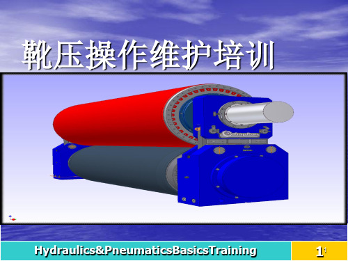
靴压操作维护培训
Hydraulics&PneumaticsBasicsTraining
11
培训内容
靴压组成 靴辊结构 靴板结构 底辊结构 靴压液压站 靴压液压控制阀盘 靴压抽油泵站
球压试验机作业指导

球压试验机作业指导一、引言球压试验机是一种用于测试材料或者产品的强度和耐久性的设备。
本文旨在提供球压试验机的作业指导,包括设备准备、操作步骤、数据记录和安全注意事项等方面的详细内容。
二、设备准备1. 球压试验机:确保球压试验机处于正常工作状态,检查电源、控制面板、传感器等部件是否完好无损。
2. 试验样品:根据需要选择合适的试验样品,并按照像关标准进行准备和标记。
三、操作步骤1. 打开球压试验机电源,并确保设备处于待机状态。
2. 将试验样品放置在球压试验机的测试台上,并根据需要进行固定。
3. 根据试验要求,在控制面板上设置合适的试验参数,如负荷大小、试验速度等。
4. 启动球压试验机,开始试验。
在试验过程中,注意观察试验样品的变形情况,并记录相关数据。
5. 在试验结束后,住手球压试验机的运行,并将试验样品从测试台上取下。
四、数据记录1. 试验参数:记录试验时设置的负荷大小、试验速度等参数。
2. 试验结果:记录试验过程中观察到的试验样品的变形情况、破坏负荷等数据。
3. 备注:可以记录试验过程中的特殊情况或者需要注意的事项。
五、安全注意事项1. 在操作球压试验机之前,确保已经了解并熟悉设备的使用说明书,遵循操作规程。
2. 在进行试验时,穿戴适当的个人防护装备,如安全帽、护目镜和手套等。
3. 注意试验样品的分量和形状,以免造成意外伤害或者设备损坏。
4. 在试验过程中,严禁将手指、手臂或者其他身体部位放置在试验样品或者机械部件的运动轨迹上。
5. 在试验结束后,及时关闭球压试验机的电源,并进行设备的清洁和维护。
六、总结本文提供了球压试验机的作业指导,包括设备准备、操作步骤、数据记录和安全注意事项等方面的详细内容。
通过按照指导进行操作,可以确保试验的准确性和安全性,提高工作效率。
在使用球压试验机时,请严格遵守相关规定和标准,确保设备的正常运行和试验结果的可靠性。
靴压的安装与换靴套说明及系统操作05

Transport and storage of the rolls1 2 3 3.1 3.2 4 4.1 4.2 4.3GENERAL INFORMATION DELIVERY TRANSPORT PrimeRoll HV Smart PrimeRoll X STORAGE PrimeRoll HV Smart PrimeRoll X Storage for a longer period2 2 3 3 4 6 6 6 727.08.20081/7KU 255-80038-05 en1General informationObserve all applicable safety and accident protection regulations. The hoists and auxiliary equipment used must be suitable for the roll transport weight: See weight specifications in the roll drawings in sections 3 and 700 of this operating manual.DANGER2Delivery-Delivery takes place in the appropriate and specialist manufacturer's packing (transport box). Only hoists and auxiliary equipment that are fully functional and appropriate for the applicable load and on which all safety mechanisms are intact may be used for the transport and unloading. Lift the transport box only at the specially-marked fastening points. Hoisting at other fastening points could damage the roll.--Transport the roll only in the original packing to the installation or storage location.Check the following: The completeness of the delivery according to delivery note. Whether the delivery is undamaged. If necessary, report transport damage at once to the carrier company, the insurance, and ANDRITZ KÜSTERS. If packing is damaged, check corrosion protection and renew if necessary.27.08.20082/7KU 255-80038-05 en3TransportTransport of the rolls outdoors or over greater distances must always be done in the transport box delivered by ANDRITZ KÜSTERS. This prevents the rolls from being damaged by external influences. The hoists and auxiliary equipment used must be suitable for the roll transport weight: See weight specifications in the roll drawings in sections 3 and 700 of this operating manual. DANGER3.1PrimeRoll HV SmartDue to the construction of the bearing in the roll consoles 1.1, the max. angle displacement may not exceed X°. If the maximum angle displacement of X° is exceeded, the bearings in the roll consoles 1.1 will be damaged. The angle displacement X° acts proportionally to the roll lift lift between operating side and drive side. Lift the rolls 1.2 therefore evenly on operating and drive side and observe the value lift 10 mm.1.11.27 lift1.11.127.08.20083/7KU 255-80038-05 en2.1a) Using a hoist (e.g., a transport cable) and crane hook, take up the roll by the ring grooves 2.1 of the roll axle on the operating and drive side. b) You can now transport the roll to its destination.3.2PrimeRoll XLifting by the traverse3.13.23.3a) Pick up the roll at the mounting plate 3.1, 3.3 of the traverse 3.2 using suitable lifting equipment (e.g., transport cable) and a crane hook. b) You can now transport the roll to its destination.27.08.20084/7KU 255-80038-05 enLifting by the roll axle When the PrimeRoll X is being lifted, the consoles could suddenly rotate around their centre of gravity in the transport cables. Secure therefore the console against tipping on the drive side in the crane hook. DANGER 4.4 4.3 4.5 (4.4) 4.6 4.7 4.1(4.3, 4.5) (4.1) (4.4)4.2 4.8c) Using a hoist (e.g., a transport cable) 4.4 and crane hook, take up the roll by the ring grooves 4.7, 4.8 of the roll axle on the operating and drive side. d) Tighten the hoists 4.4. e) Secure the console 4.1 of the drive side to the installation eyes 4.2, 4.6 with hoists (e.g. transport cable or ratchet feed winches) 4.3, 4.5 against turning. f) You can now transport the roll to its destination.27.08.20085/7KU 255-80038-05 en44.1StoragePrimeRoll HV Smart-Put the roll down on the roll axle (see arrows). or Deposit the roll with the consoles onto a stable and even supporting surface.-4.2PrimeRoll X-Put the roll down on the roll axle (see arrows).27.08.20086/7KU 255-80038-05 en4.3Storage for a longer periodIf the PrimeRoll X is stored for a longer time (i.e. longer than during a usual removal or installation of the roll) with the shoe in the 6 o'clock position (installation position in the machine), then the shoe presses against the belt (see arrow) and can deform it permanently.8.1 Always store the PrimeRoll X for longer periods in the transport box, because the shoe or the belt is relieved by the supports 8.1 in the transport box. Always store the PrimeRoll X, the PrimeRoll HV Smart as well as the remaining components in the transport boxes or in the original packaging until assembly. Storage has to take place under the following conditions: Dry and well-ventilated room Constant temperature ranging from 15 to 30 °C No major temperature fluctuations No possibility of humidity entering No heat radiation No chemical influences For further information on the belt, please refer to the documentation of the belt manufacturer found in section 700 of this operating manual.27.08.20087/7KU 255-80038-05 en。
- 1、下载文档前请自行甄别文档内容的完整性,平台不提供额外的编辑、内容补充、找答案等附加服务。
- 2、"仅部分预览"的文档,不可在线预览部分如存在完整性等问题,可反馈申请退款(可完整预览的文档不适用该条件!)。
- 3、如文档侵犯您的权益,请联系客服反馈,我们会尽快为您处理(人工客服工作时间:9:00-18:30)。
Shoe exchange on the PrimeRoll XContents1GENERAL INFORMATION 2 2REQUIREMENTS 2 2.1Depositing the roll 3 3ROTATING THE ROLL TO THE MOUNTING POSITION 4 4REMOVING THE OLD SHOE 5 5INSTALLING THE NEW SHOE 7 6ROTATING THE ROLL TO THE INSTALLATION POSITION 9 7MOUNTING THE BELT 91General informationRemove any remaining oil from the slinging points before slingingcommences.All auxiliary equipment, for example supports (racks) and liftingequipment such as ropes, slings and straps, have to be capable ofsupporting the loads to be lifted. To find out the weights of the roll, pleaserefer to the roll drawing in Chapters 3 found in this operating manual.2RequirementsThe roll has been removed from the machine.The transport traverse has been taken from the consoles.The belt has been removed.To remove the belt, please read the documentationKU 255-80038-04, Chapter 4.DANGER2.1 Depositing the rollTo rotate the roll, put it down on suitable support blocks with V-block mountings 1.1 made of hardwood. By depositing the roll in the V-block mountings 1.1, it can be rotated securely and in a controlled manner.Danger of injuries from swinging roll!The roll axle could pivot around its centre of gravity after being deposited on the pedestals. Therefore, support the roll below the console 2.3 on the drive side.a) Deposit the roll with the roll journals on supporting stands 2.2, 2.4 with V-block mountings made of hardwood.b) Support the console 2.3 on the drive side with a support 2.1 (e.g. with a wooden rack).c)Remove the hoisting gear and the crane hooks.2.32.42.22.11.1DANGER3Rotating the roll to the mounting positiona) On the drive side in the console 3.1 hook a hoist (e.g. transport belt) 3.2 to the crane hook and to the bolt 3.5.b) On the operating side in the console 3.3 hook a hoist (e.g. transport belt) 3.4 to the crane hook and to the bolt 3.6.c) Remove the support 3.7.d) Turn the roll by swivelling the console 3.1 carefully by 180°. Pull the console 3.1 around with the hoist 3.2 and secure the roll from suddenly swinging around by continualy adjusting the hoist 3.4.e) Support the console 3.1 on the drive side with a support 4.1 (e.g. with a wooden rack). f) Remove the hoists 3.2 and 3.4.(3.2)3.43.63.73.5(3.4)3.23.33.1(3.2)4.1(3.4)(3.1)4Removing the old shoea) Attach the four transport brackets 5.3, 5.6 with the screws 5.2, 5.7 to the shoe 5.5.b) Pick up the shoe 5.5 at the transport brackets 5.3, 5.6 using a hoist (e.g., transport cables) 5.4 and a crane hook.c) Remove the four securing screws 6.1 from the shoe 6.2.d) Lift the shoe 5.5 (6.2) as much as necessary and remove the two temperature sensors 5.1, 5.8 from the shoe 5.5.e) Carefully lift the shoe 6.2 down from the roll axle 6.3.5.15.25.35.75.6 5.45.55.86.16.16.26.36.4f) Remove the screws 7.3 from both holders 7.2.g) Screw in two screws 7.3 each into the forcing thread of the holders 7.2 andpress them out of the shoe 7.1 by evenly tightening the screws 7.3.h) Mount the two holders 7.2 to the new shoe 7.1.i) Disassemble the protective pipe 7.4 from the shoe 7.1 and mount it to thenew shoe.j) Place the old shoe 7.1 on a clean base in the depositing area.k) Remove the transport brackets 5.3, 5.6 from the shoe 5.5 (7.1).7.27.4 7.1 7.35Installing the new shoea) Attach the four transport brackets 8.2, 8.5 with the screws 8.1, 8.9 to the shoe 8.3.b) Pick up the shoe 8.3 at the transport brackets 8.2, 8.5 using a hoist (e.g., transport cables) 8.4 and a crane hook. Take care during the lowering of the shoe 8.3 that the holders 8.8 on the shoe 8.3 slide over the guide journals 8.6 of the roll axle 8.10.8.18.2 8.88.4 8.58.98.38.68.10c) Lower the shoe 9.4 until you can mount the temperature gauges 9.1, 9.7.d) Turn both temperature gauges 9.1, 9.7 in the shoe 9.4.e) Place the shoe 9.4 on the shoe elements 9.9 of the roll axle 9.8.f) Turn the four securing screws 10.2 with the spacer pipes 10.3 into the shoe 10.1.g) Remove the transport brackets 9.2, 9.6 and the hoist 9.3.10.310.2 10.19.19.29.69.39.49.79.99.86Rotating the roll to the installation positiona) On the drive side in the console 11.1 hook a hoist (e.g. transport belt) 11.2 to the crane hook and to the bolt 11.5.b) On the operating side in the console 11.3 hook a hoist (e.g. transport belt) 11.4 to the crane hook and to the bolt 11.6.c) Remove the support 11.7.d) Turn the roll by swivelling the console 11.1 carefully by 180°. Pull the console 11.1 around with the hoist 11.2 and secure the roll from suddenly swinging around by continualy adjusting the hoist 11.4.e) Support the console 11.1 on the drive side with a support 12.1 (e.g. with a wooden rack). f) Remove the hoists 11.2 and 11.4.7Mounting the beltTo mount the belt, read the corresponding passages in Chapter 9 of the documentation KU 255-80038-04.(11.2)11.411.611.711.5(11.4)11.211.311.1(11.2)12.1(11.4)(11.1)。