DN50-25液化气鹤管说明书
燃气使用说明书
燃气使用说明书1. 引言燃气作为一种常见的能源,被广泛应用于烹饪、供暖等方面。
为了安全和高效地使用燃气,本燃气使用说明书旨在向用户提供必要的指导和注意事项。
2. 安全使用燃气的基本知识2.1 燃气的性质燃气主要由天然气和液化石油气(LPG)两种形式存在。
用户在购买和使用燃气时,需要了解其分配形式、成分和性质,以确保正确的应用。
2.2 燃气的安全性燃气具有易燃、可燃等性质,正确使用和安装燃气设备是确保安全的重要条件。
用户在操作燃气设备时,应严格按照使用说明进行操作,并遵守相关的安全规定。
3. 安全使用燃气的注意事项3.1 安装燃气设备用户在购买燃气设备时,应选择合格的产品,并请专业人士进行安装。
安装前应确认气源是否畅通,设备是否符合要求,并严格按照制造商提供的安装说明进行操作。
3.2 使用燃气设备使用燃气设备时,用户需注意以下事项:- 在操作前,请确保燃气设备的管路与阀门是否处于正常状态。
- 使用燃气设备时,请确保通气良好,避免在密闭空间内使用。
- 遵循正确的点火程序,严禁使用明火等不安全的点火源。
- 在使用过程中如发现气味异常或其他安全隐患,请立即停止使用并关闭燃气阀门。
- 长时间不使用燃气设备时,请关闭阀门以防止安全事故发生。
3.3 如遇到安全问题若出现燃气泄漏、燃气设备异常以及其他安全问题时,请迅速采取以下措施:- 避免操作产生火花或其他燃烧源,确保周围环境无明火等火源。
- 迅速关闭燃气阀门,并开启窗户通风。
- 禁止点灯、启动电器或其他可能引起火花的动作。
- 立即拨打燃气供应公司的紧急联系电话,报告事故并请相关专业人士前来处理。
4. 维护和保养为确保燃气设备的正常运行和延长使用寿命,用户需要进行定期的维护和保养。
具体操作请按照设备使用说明书进行,遵循厂家提供的维护建议。
5. 废弃和废气处理废弃燃气设备时,请与当地相关部门联系,了解正确的处理方式。
废气处理方面,应遵循环保要求,尽量减少对环境的污染。
鹤管资料——精选推荐

鹤管资料鹤管顾名思义,⼀种可以伸缩移动的管⼦,多⽤于⽯油、化⼯码头液体装卸,管内介质如油、⽔等。
常见规格8〞—20〞不等。
鹤管是⽯化⾏业流体装卸过程中的专⽤设备。
它采⽤旋转接头与刚性管道及弯头连接起来,以实现⽕车、汽车槽车与栈桥储运管线之间传输液体介质的活动设备,以取代⽼式的软管连接,具有很⾼的安全性,灵活性及寿命长等特点。
产品符合GBJ74-84《⽯油库设计规范》标准,是收发油料⼯艺中⼀种理想的专⽤设备,也可⼴泛⽤于化学⼯业及其他⾏业收发各类液体原料。
鹤管分:汽车装卸鹤管、⽕车装卸鹤管、飞机装卸鹤管、桶装鹤管等。
铁路、公路装卸油鹤管主要⽤于铁路油槽车和公路油罐汽车的装卸流体作业的专⽤设备。
从装卸型式上可分为上装上卸和下⽅装卸。
可输送有介质有原油、汽油、柴油、润滑油等⽯油产品;也可输送浓硫酸、液化天然⽓、液化⽯油⽓、溶融硫磺、沥青、⼆硫化碳等化⼯产品。
鹤管主要由固定、回转、操作、平衡等机构和油管组成。
其中、回转机构(回转接头)是⽤锻钢或铝合⾦精⼼制造,内装复列球轴承,不锈钢特殊密封圈,它旋转灵活、密封性能可靠、经久耐⽤。
平衡系统有配重、扭簧、压簧、拉簧和丝杠以及液压和⽓动平衡等型式,均能以很⼩的⼒进⾏操作。
⽕车装卸油鹤管:所有鹤管均带⽴柱,为液下装车;鹤管的装车垂直管均采⽤铝合⾦管;与⽕车槽车、汽车罐车对接⽅便;甲醇⽤⽕车、汽车装车鹤管均采⽤密闭式,要求有⽓相回收管。
其它说明: a具有报警功能,槽车液位现场显⽰并可接送DCS系统⾃动控制⾮本装卸设备装置,需另外配备设施。
b装车阀采⽤现场⼿动,亦⾮本装卸设备装置,为管道设施。
c电⽓控制应设置现场开停按钮,并能接受或输出信号⾄客户DCS系统实现控制室运⾏指⽰功能,此项功能亦⾮本装卸设备装置。
d电⽓设备防护等级IP54、绝缘等级F、防爆等级为DIIBT4,应满⾜室外设备安装要求。
由于醋酸在环境温度低于160C就开始结晶,保证鹤管内⾮⼯作状态⽆醋酸滞留,安装时将鹤管采⽤到装。
液化天然气(LNG)运行操作手册
液化天然气(LNG)气化站运行操作手册上海清泰液化天然气有限公司编制二零零五年八月公司简介上海清泰液化天然气有限公司是一家致力于液化天然气(LNG)事业发展、集投资开发与工程建设于一体的专业化公司,伴随着中国LNG产业发展而成长.公司汇集一批在LNG产业领域里从事理论研究和工程实践的先行者,围绕LNG资源进口、储运、终端利用和技术研发开拓业务,为促进国家能源结构变革、提高能源综合利用效率、保护生态环境而进行着努力和探索。
上海清泰公司奉行“真诚合作、协调发展”的企业精神,不断追求先进的项目管理模式,努力打造清泰品牌。
清泰公司愿与燃气界同行一起努力,共同推动中国LNG产业发展,为LNG在中国的广泛普及应用作出积极贡献。
联系方式:上海清泰液化天然气有限公司公司地址:上海浦建路145号强生大厦1602室联系电话:021—50899290,50899291传真号码:021-********液化天然气(LNG)气化站运行操作手册目录公司简介 0目录 (1)第一章天然气与液化天然气(LNG)知识 (4)1。
1 天然气知识 (4)1。
1.1 天然气组成 (4)1.1。
2 天然气燃烧特性 (5)1.1.3 天然气的储运 (6)1。
2 LNG基本性质 (8)1。
2。
1 LNG组分 (8)1。
2.2 LNG物性数据 (9)1。
2.3 LNG特点 (9)第二章LNG气化站工艺介绍 (11)2。
1 气化站工艺流程 (11)2.1。
1卸车工艺 (12)2。
1。
2 贮存增压工艺 (12)2。
1.3 气化加热工艺 (13)2.1。
4 BOG处理工艺 (13)2.1.5 安全泄放工艺 (14)2.1.6 计量加臭工艺 (14)2。
2 气化站布置 (15)2。
3 LNG气化站主要设备 (15)2。
3.1 LNG储罐 (15)2.3.2 空浴式气化器 (16)2。
3。
3 水浴式加热器 (16)2.3。
4 缓冲罐 (16)2.3。
5 加臭装置 (17)2。
煤气罐(液化石油气钢瓶)主要技术参数及使用说明
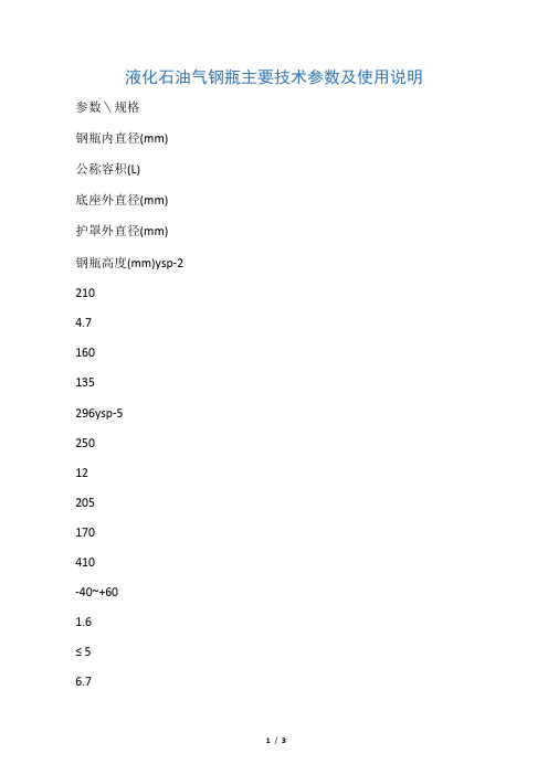
液化石油气钢瓶主要技术参数及使用说明参数\规格钢瓶内直径(mm)公称容积(L)底座外直径(mm)护罩外直径(mm)钢瓶高度(mm)ysp-22104.7160135296ysp-525012205170410-40~+601.6≤ 56.76.7ysp-1031423.5240190535-40~+602.1≤ 10ysp-1531435.5240190680-40~+602.1≤ 15ysp-50 4001184001901215-40~+602.1≤ 50适用环境温度(℃)-40~+60 公称工作压力(Mpa)充装重量(kg)设计重量(kg)设计重量(kg)1.6≤24.34.3I型护罩12.7I型护罩16.3I型护罩50.4II型护罩12.5II型护罩16.1II型护罩50.2正确使用石油液化气钢瓶,是杜绝钢瓶泄漏、火灾和爆炸事故的根本保证。
为了您和您家人的安全,请正确使用液化气钢瓶。
1、新充装的钢瓶在第一次使用前,应检查瓶体及附件角阀、减压阀各部分所连接处是否接牢和漏气。
2、严禁用火烤或60℃以上热水等办法来加热钢瓶;严禁私自进行相互倒瓶;严禁钢瓶超期使用。
3、液化石油气瓶与煤球炉不宜同室使用,钢瓶不得靠近热源,如暖气片、火炉、煤炉等,钢瓶和气灶应保持1米以上的距离。
4、存放液化气钢瓶的房屋应注意通风良好。
液化气钢瓶在使用中不应离人。
特别是在瓶内气体快要用完或小火燃烧时易于熄灭,造成液化气泄漏,这些是造成火灾或致死人命等事故的重要原因。
5、液化气钢瓶发生泄漏时,要迅速开启门窗,切不可动用明火(包括开关电灯、排风扇等电源设备)。
以降低气体浓度,消除事故隐患。
6、钢瓶到检验期或发现瓶体缺陷、零附件损坏时,应及时送钢瓶检验单位检测、修理,不得私自拆修(钢瓶使用不满20年者,每5年检验1次;使用20年以上者,每2年检验1次;当钢瓶受到严重腐蚀或损伤时,应提前进行检验)。
<上海天然气有限公司>。
Carrier 10-20吨液化气暖通系统产品说明书

Installation Instructions -10 -20 -25 -25TABLE OF CONTENTS PACKAGE CONTENTS1......................... PACKAGE USAGE1............................. SAFETY CONSIDERATIONS1.................... GENERAL2 .................................... INSTALLATION2--12............................ Relay--Transformer Package--10to20TonSplit System Condensing Units with Semi--Hermetic Compressors with R--22Refrigerant2.................... Winter Start Accessory--6to10Ton Split System Condensing Units with Hermetic Compressors and71/2to20Ton Split System Condensing Units withSemi--Hermetic Compressors with R--22Refrigerant3....... Winter Start Accessory--12to20Ton High--Efficiency Medium Rooftop Units with R--22Refrigerant5............ Winter Start Accessory--12to25Ton Standard Efficiency Medium Rooftop Units with R--22Refrigerant8............ Winter Start Accessory--3to10Ton Units with Puron R Refrigerant10 .......................................IMPORTANT:Read these instructions completely before attempting to install the accessory.PACKAGE CONTENTSWINTER START ACCESSORYCRWINSTR001A00QTY CONTENTS1Time---Delay Relay HN67XZ210 RELAY--TRANSFORMER ACCESSORYCATRANRY001A00QTY CONTENTS1Relay Box Assembly3Connector Wires1Bushing and Locknut2Quick---Connect Terminals2Ring Terminals4No.10Screws1Wire AssemblyPACKAGE USAGEUNIT ACCESSORY PARTNUMBER10to20T on Split SystemCondensing Units withSemi---HermeticCompressors with R---22RefrigerantCRWINSTR001A00CATRANRY001A006to10T on Split SystemCondensing Units withHermetic Compressors withR---22RefrigerantCRWINSTR001A0071/2to10T on Split SystemCondensing Units withSemi---HermeticCompressors with R---22Refrigerant12to20T on StandardEfficiency Medium RooftopUnits with R---22Refrigerant12to25T on StandardEfficiency Medium RooftopUnits with R---22Refrigerant3to10T on Rooftop Unitswith Puron Refrigerant CRWINSTR001A00SAFETY CONSIDERATIONS Installation and servicing of air--conditioning equipment can be hazardous due to system pressure and electrical components.Only trained and qualified service personnel should install,repair,or service air-conditioning equipment. Untrained personnel can perform the basic maintenance functions.All other operations should be performed by trained service personnel.When working on air-conditioning equipment,observe precautions in the literature,tags and labels attached to the unit,and other safety precautions that may apply.Follow all safety codes.Wear safety glasses and work gloves.Recognize safety information.This is the safety--alert symbol.When you see this symbol on the unit and in instructions or manuals,be alert to the potential for personal injury.Understand the signal words DANGER,WARNING,and CAUTION.These words are used with the safety--alertsymbol.DANGER identifies the most serious hazards which will result in severe personal injury or death.WARNING signifies a hazard which could result in personal injury or death.CAUTION is used to identify unsafe practices which may result in minor personal injury or product and property damage.NOTE is used to highlight suggestions which will result in enhanced installation,reliability,or operation.GENERALWinter Start Accessory CRWINSTR001A00provides a 3-minute time delay for the low-pressure switch to prevent nuisance trips due to low ambient temperature.Relay-Transformer Accessory CATRANRY001A00enables installation of multiple liquid line solenoids and other larger 24-v loads.Two winter start relays are required for all large rooftop units.INSTALLATIONRelay--Transformer Package —10to 20Ton Split System Condensing Units and Semi--Hermetic Compressors with R--22RefrigerantRefer to unit label diagram and install Relay-Transformer Package CATRANRY001A00in condensing unit as follows:1.Install component below Terminal Block 2(TB2)in unit control box.A knockout is provided in the bottom of the control box for running wires from the accessory to TB2.ing the bushing nut (coupler)provided,route the 6wires through the knockout and tighten the bushing nut.3.Secure side of accessory to condensing unit using 2screws provided.(See Fig.1.)4.Connect wires to unit controls as shown in Fig.2.RELAY-TRANSFORMER PACKAGEINSTALL WINTER START ACCESSORYC07471Fig.1--Recommended Locations for Accessory Components in 10to 20Ton Split System Condensing Units with Semi--Hermetic Compressors with R--22RefrigerantWinter Start Accessory—6to10Ton Split System Condensing Units with Hermetic Compressors and71/2to20Ton Split System Condensing Units with Semi--Hermetic Compressors with R--22RefrigerantRefer to unit label diagram and install Time-Delay Relay (TDR),in condensing unit as follows:For10to20ton split system condensing units with semi--hermetic compressors:1.See Fig.1for location of Time-Delay Relay(TDR).e field-supplied screws and be certain mountingholes are positioned upwards(Fig.4),as device isposition-sensitive.3.Run field-supplied wires from quick-connectterminals in device to unit controls as shown in Fig.5.All wires must be18AWG(American WireGauge).For6to10ton split system condensing units with hermetic compressors or71/2to10ton split system condensing units with semi-hermetic compressors:1.See Fig.3for location of TDR.e field-supplied screws and be certain mountingholes are positioned upwards(Fig.4),as device isposition-sensitive.3.Run field-supplied wires from quick-connectterminals in device to unit controls as shown in Fig.6.All wires must be18AWG(American WireGauge).C07472LEGENDC---Compression ContactorCM---CommonHD---Heat DeviceHT ANT.---Heat AnticipatorIFC---Indoor-Fan ContactorIFR---Indoor-Fan RelayLLS---Liquid Line SolenoidR---Accessory Relay(Field Supplied)RC---Relay,CoolingRH---Relay,HeatingSVR---Solenoid Valve RelayTB---Terminal BlockTC---Thermostat CoolingTH---Thermostat HeatingTRAN---Transformer____---Field-Supplied WiringFig.2--Relay--Transformer AccessoryWiringINSTALL WINTERC07473Fig.3--Recommended Location for Winter Start Accessory (Time--Delay Relay)in6to 10Ton Split System Condensing Units with Hermetic Compressors and 71/2to 10Ton Split System CondensingUnits with Semi--Hermetic Compressors with R--22RefrigerantC07474Fig.4--Top View,Winter Start Accessory(Time--Delay Relay)C07475Fig.5--Connection Points,Time--Delay Relay,Winter Start Accessory;10to 20Ton Split System Condensing Units with Semi--Hermetic Compressorswith R--22RefrigerantWinter Start Accessory—12to20TonHigh--Efficiency Medium Rooftop Units with R--22RefrigerantRefer to unit label diagram and install Time-Delay Relay (TDR)in unit as follows:1.Install the Time-Delay Relay in the area shown in thecontrol box using field-supplied screws.(See Fig.7.)2.Ensure the top terminals are up,as device isposition-sensitive.(See Fig.4.)3.Run field-supplied18AWG(American Wire Gauge) wires from quick-connect terminals in the device to the unit as shown in Fig.8.4.Repeat Steps1and2for all units.A second relay is required.(See Fig.8.)C07476Fig.6--Connection Points,Time--Delay Relay,Winter Start Accessory6to10Ton Split System Condensing Units with Hermetic Compressors and 71/2to10Ton Split System Condensing Units with Semi--Hermetic Compressors with R--22RefrigerantC07477Fig.7--Typical Control Box for 12to 20Ton High--Efficiency Medium Rooftop Units with R--22RefrigerantC07478 Fig.8--Connection Points,Time--Delay Relay,Winter Start Accessory;12to20Ton High--Efficiency Medium Rooftop Units with R--22RefrigerantWinter Start Accessory —12to 25Ton Standard Efficiency Medium Rooftop Units with R--22RefrigerantRefer to unit label diagram and install time-delay relay(s)(TDR)in unit as follows.Note that 2TDRs are required for all units.1.Install the Time-Delay Relay(s)in the area shown in the control box,using field-supplied screws.(See Fig.9.)2.Ensure the top terminals are up,as device is position-sensitive.(See Fig.4.)3.Run field-supplied 18AWG (American Wire Gauge)wires from quick-terminals in the device(s)to the unit as shown in Fig.10.4.Repeat Steps 1and 2for the second circuit.(See Fig.10.)C07479Fig.9--Typical Control Box for 12to 25Ton Standard Efficiency Medium Rooftop Units with R--22Refrigerant(208/230V Gas Heat UnitShown)C07480 NOTES:1.Control relays CR1and CR2are replaced by C1and C2in460---v and575---v units.2.Connection points shown are typical for each relay;a relay(CR)and contactor(C)are supplied on each circuit for25ton units.Fig.10--Connection Points,Time--Delay Relay,Winter Start Accessory;12to25Ton Standard Efficiency Medium Rooftop Units with R--22RefrigerantWinter Start Accessory —3to 10Ton Rooftop Units with Puron R RefrigerantRefer to unit label diagram and install Time--DelayRelay(s)(TDR)in unit as follows.1.Install the Time--Delay Relay(s)in the area shown inthe control box,using field--supplied screws.(SeeFig.11.)2.Ensure the top terminals are up,as device is position--sensitive.(See Fig.4.)3.Run field--supplied 18AWG (American Wire Gauge)wires from quick--connect terminals in the device(s)to the unit as shown in Fig.12.4.Repeat Steps 1and 2for any models with second circuit of cooling.C08279Fig.11--Winter Start Accessory Location for 3--10Ton Rooftop Units with Puron R Refrigerant and Single CircuitWinter Start AccessoriesC08277Fig.12--Winter Start Accessory Location for 7.5--10Ton RooftopUnits with Puron Refrigerant,Two Circuits and No Cycle Loc ControlWinter Start AccessoryC08278 Fig.13--Winter Start Accessory Location for7.5--10Ton Rooftop Units with Puron R Refrigerant,Two Circuits and Cycle Loc ControlUnit Terminal BoardC08280 Fig.14--Single CircuitUnit Terminal BoardC08281Fig.15--Two CircuitCopyright 2008CAC /BDP D 7310W.Morris St.D Indianapolis,IN 46231Printed in U.S.A.Edition Date:4/08Manufacturer reserves the right to change,at any time,specifications and designs without notice and without obligations.Catalog No:IIK---CRWNTRAN01---01Replaces:38/48/50---9SI。
LNG程式气动加液枪使用说明书

整个操作过程只需要拔出和按下控制器的按钮,一个动作即 可完成连接、充装以及脱离退枪等系列操作,极大地降低了操作 人员的劳动强度;
破冰:采用强制破冰结构设计,能够实现 LNG 加注过程的长
第7页
序号 代号/规格型号
1
FH023403
2
150104-21
3
内径 90x内径 54.5x3.55
6 内径 54.5x2.65
7
外径 14x3.55
8
外径 8x1.00
9
外径 10x1.80
10
内径 7x1.80
11 内径 10x1.80
名称 泛密封 密封圈 O 型圈 O 型圈 O 型圈 O 型圈 O 型圈 O 型圈 O 型圈 O 型圈 O 型圈
穿戴下列保护服装: 安全面罩、低温专用手套、低温工作服、 耐低温液体的防护鞋。 第2步
每天第一次加液前,确保加液枪端口处没有压力。然后用一 块干净、干燥的布擦拭加液枪和加气口接触处。 第3步
拿开加气口防尘罩,握住手柄,把加液枪沿加气口方向推入。 第4步
拔出红色控制按钮,开始加液。 第5步
加注完毕时,按下红色控制按钮,停止加注,移开加液枪。 第6步
第1页
时间连续作业,减少了 LNG 加注时的氮气吹扫过程; 密封:合理的密封设计保证加注时无泄漏;内置止回阀,加
液过程中,加液枪与加气口异常脱离后,低温液体不至于外漏; 维护:结构简单,生产制造便捷、使用以及维护方便,客户
的使用及维护保养成本较低,体积小,重量轻,采用按键式操作, 不受操作空间的限制。
3.5 MPa(表压) 225 L/min -196℃ ~ +50℃
燃气设备操作说明书

燃气设备操作说明书操作说明书1. 引言燃气设备是一种常见的能源和热力设备,具有广泛的应用领域。
为了确保用户正确、安全地操作燃气设备,本操作说明书将详细介绍燃气设备的操作流程和注意事项。
2. 设备概览燃气设备由以下几个主要部分组成:2.1 燃气供应系统:包括燃气管道、阀门、压力调节器等;2.2 热交换器:用于将燃气的能量转换为热能;2.3 控制系统:包括燃气控制阀、温度控制器、传感器等。
3. 操作流程3.1 准备工作在操作燃气设备之前,确保以下几点:- 设备安装完好且连接正确;- 燃气供应系统正常运行;- 环境通风良好。
3.2 启动设备3.2.1 打开燃气供应将燃气供应系统的主阀门缓慢打开,确保正常供气。
3.2.2 启动点火将点火源靠近燃气喷射器,并打开点火开关,点火器点燃燃气,同时观察火焰是否正常。
3.2.3 等待预热在启动后,等待设备达到预定的工作温度,这将需要一定的时间。
3.3 调节温度使用温度控制器,根据需要设定所需工作温度。
温度控制器会自动控制燃气进出的流量,以维持设定温度。
3.4 关闭设备在使用完毕后,按照以下步骤关闭燃气设备:3.4.1 关闭燃气供应将燃气供应系统的主阀门缓慢关闭,停止供气。
3.4.2 熄灭火焰关闭点火开关,并等待设备冷却后彻底熄灭火焰。
3.4.3 断开电源关闭设备的电源开关。
4. 注意事项4.1 安全操作- 在操作燃气设备时,确保操作环境通风良好,避免气体积聚引发安全事故。
- 遵循使用说明书提供的操作步骤,不得随意调节设备参数。
- 注意设备工作温度和压力的变化,确保设备在正常范围内运行。
4.2 定期维护- 定期对燃气设备进行维护,保持设备的正常运行状态。
- 清洁燃气喷射器等关键部件,确保其通畅无堵塞。
- 检查燃气供应系统的安全阀等关键部件,确保其正常工作。
5. 故障排除在使用燃气设备过程中,可能会遇到以下故障情况:- 火焰异常:如果看到火焰颜色异常或火焰不稳定,应立即关闭设备,并联系售后服务人员进行检修。
煤气罐液化石油气钢瓶主要技术参数及使用说明

液化石油气钢瓶主要技术参数及使用说明
正确使用石油液化气钢瓶,是杜绝钢瓶泄漏、火灾和爆炸事故的根本保证。
为了您和您家人的安全,请正确使用液化气钢瓶。
1 、新充装的钢瓶在第一次使用前,应检查瓶体及附件角阀、减压阀各部分所连接处是否接牢和漏气。
2 、严禁用火烤或60 ℃以上热水等办法来加热钢瓶;严禁私自进行相互倒瓶;严禁钢瓶超期使用。
3 、液化石油气瓶与煤球炉不宜同室使用,钢瓶不得靠近热源,如暖气片、火炉、煤炉等,钢瓶和气灶应保持1 米以上的距离。
4 、存放液化气钢瓶的房屋应注意通风良好。
液化气钢瓶在使用中不应离人。
特别是在瓶内气体快要用完或小火燃烧时易于熄灭,造成液化气泄漏,这些是造成火灾或致死人命等事故的重要原因。
5 、液化气钢瓶发生泄漏时,要迅速开启门窗,切不可动用明火(包括开关电灯、排风扇等电源设备)。
以降低气体浓度,消除事故隐患。
6 、钢瓶到检验期或发现瓶体缺陷、零附件损坏时,应及时送钢瓶检验单位检测、修理,不得私自拆修(钢瓶使用不满20 年者,每5 年检验1 次;使用20 年以上者,每2 年检验1 次;当钢瓶受到严重腐蚀或损伤时,应提前进行检验)。
< 上海天然气有限公司>。