HK1235使用说明书-BDTIC
海信 LHD32K3500HK 液晶电视使用说明书

LHD32K3500HK产品使用说明书请在使用本机之前,仔细阅读并保留备用海信香港网址 海信社区 温馨提示您好!在使用本产品前请您认真阅读产品使用说明书,并妥善保管。
因违反本手册中安全注意事项及使用说明事项而导致的事故,本公司不承担任何责任。
本产品内有高压,用户不得擅自打开机壳。
非维修人员,不得擅自修理和换件,以免发生触电和火灾事故。
请用干净、柔软的綿布对整机进行清洁维护,禁止反复用力擦拭。
禁止用硬物划刻、敲打、撞击或用各种研磨类物品摩擦显示屏。
本产品在安放、使用时应避免受到水滴、水溅。
遇到雷雨等不良天气,应迅速拔下电源插头及有线电视(或室外天线)插头,以免发生雷击损坏事故。
静止图像可能会导致电视屏幕永久性损坏。
1 不要在液晶电视屏幕上显示静止图像超过2小时,因为这样会导致出现屏幕图像残影,为避免此问题请您在显示静止图像时降低屏幕的亮度和对比度。
2 长时间观看4:3格式的节目时,在屏幕的左、右两侧和图像的边缘会留下不同的痕迹,所以请您不要长时间使用此模式。
3 显示电子游戏和电脑静止图像的时间过长,可能会导致局部余像,出现因荧光屏灼伤而造成的屏幕图像残影,所以请您在使用时适当降低亮度和对比度。
上述原因导致的电视机屏幕出现图像残影、局部余像、痕迹问题,显示屏不在保修范围之内。
本机为Ⅱ类设备,不需要接地使用。
更多产品功能介绍,您可以参见电视机内置特色应用指南。
节能提示:1 在不观看电视节目时请选择交流关机(通过电视机电源开关关机),以减少能耗。
2 在不影响观看质量的前提下,可降低显示屏的亮度以减少电视机在使用过程中的能耗。
使用本产品前请详细阅读下列事项:带闪电箭头的三角形图案为警告符号,提醒您注意产品内的电压有危险。
√表示正确的做法。
带惊叹号的三角形图案为警告符号,提醒您注意与产品有关的重要说明。
×表示错误的做法。
·注意事项。
->下一步。
符号说明重要注意事项1安全警告遇到雷雨时,请将电源插头拔出,并将有线电视插头或室外天线插头拔出,以免造成电视机损坏。
HK1235-7中文资料
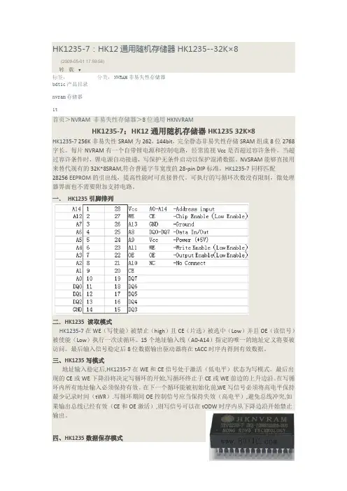
HK1235-7:HK12通用随机存储器HK1235--32K×8(2009-05-01 17:59:56)转载▼标签:分类:NVRAM非易失性存储器bdtic产品目录nvram存储器it首页>NVRAM 非易失性存储器>8位通用HKNVRAMHK1235-7:HK12通用随机存储器HK1235 32K×8HK1235-7 256K非易失性SRAM为262,144bit,完全静态非易失性存储SRAM组成8位2768字长。
每片NVRAM有一个自带锂电源和控制电路,经常监视Vcc是否超过容许条件。
当超过容许条件时,锂电源自动接通,写保护无条件启动以保护混淆数据。
NVSRAM能够直接用来替代现有的32K*8SRAM,符合普通字节宽度的28-pin DIP标准。
HK1235-7同样匹配28256 EEPROM的引出线,提高性能时可直接替代。
可执行的写循环次数没有限制,微处理器界面也不需要附加支持电路。
一.HK1235引脚排列二.HK1235 读取模式HK1235-7在WE(写使能)被禁止(high)且CE(片选)被选中(Low)并且OE(读信号)被使能(Low)执行一次读循环。
15个地址输入线(A0-A14)指定的唯一的地址定义将要被访问。
最后输入信号稳定后8位数据输出驱动器将在tACC时序内得到有效数据。
三、HK1235写模式地址输入稳定后,HK1235-7在WE和CE信号处于激活(低电平)状态为写模式。
最后出现的CE或WE下降沿将决定写循环的开始,写循环终止于CE或WE前边的上升边沿。
在写循环内所有地址输入必须保持有效。
在下一个循环能被初始化前,WE写信号必须将高电平保持最少记录时间(tWR).写循环期间OE控制信号应当保持失效(高电平),避免总线冲突,如果输出总线已经有效(CE和OE激活),则写信号可以在tODW时序内从下降边沿开始禁止输出。
四、HK1235数据保存模式HK1235-7为Vcc提供全部功能,当VCC大于4.5伏或4.75伏,写保护为4.35伏或4.75伏。
半导体激光打标机说明书
半导体激光打标机使用说明书深圳市华天世纪激光科技有限公司前言欢迎您选用我公司生产的HT-DP50系列激光打标机,如果您是首次使用此款型号的激光打标机,在通电前请务必仔细阅读本使用手册。
DP50系列激光设备已采用了尽可能全面的安全防范措施,以确保拥护人身安全及设备的自身安全,虽然如此,对本机的不正确使用、维护、改制等仍可能对操作者或机器造成各种损害。
防止激光辐射的泄漏:DP50系列激光设备采用封闭的激光光路设计,可以有效地防止激光辐射的泄漏。
对本机电器设备进行的维护、调整必须由经过培训的对本机各部分均较为熟悉的专业技术人员进行,且需特别注意以下几点:1、若某部件在维护调整时不需要运行,请勿接通该部分的电源。
2、在更换激光器模块时,切勿接通设备电源。
3、机器应有良好的接地,并应对此作定期检查。
4、尽可能只用一只手操作电气设备,以防止在人体上构成回路。
5、在高压电路上操作时,应使用合格的,绝缘良好的工具。
设备的测试,有些需采用一些特殊的测量技术或设备。
测试参数的选择应由熟悉本机操作和相关设备使用的技术人员决定。
敬告用户:1、除本手册所规定的操作外,对机器的任何其他操作,都可能使操作者遭受危险的激光辐射!2、若激光束照射到易燃材料上时,将会引起火灾甚至爆炸,应注意不得把该类材料放置到光路上或激光束有可能照到的地方!3、激光器正常工作期间,设备内部不得增设任何零件及物品。
除非经过特别授权,否则不得在密封罩打开的状态下使用本机。
欢迎用户提出建议,请与下列地址联系:中华人民共和国深圳市华天世纪激光科技有限公司邮政编码:518001电话:国内业务部:0国际业务部:+86-售后服务部:0传真:(FAX):1主页:H地址:深圳市罗湖区人民北路物资大院综合楼1-2层需要采购或技术支持时,请与就近的销售服务商联系目录第一部分半导体激光打标机各部件原理与使用说明............................................................................. - 1 -1.激光原理....................................................................................................................................... - 1 -2.光学系统....................................................................................................................................... - 1 -3.各主要部件原理与技术说明....................................................................................................... - 2 -扩束镜........................................................................................................................................... - 4 -激光电源....................................................................................................................................... - 4 -声光Q开关.................................................................................................................................. - 8 -声光Q开光驱动电源.................................................................................................................. - 8 -1.电气安装连线....................................................................................................... - 8 -1、数码窗................................................................................................................. - 10 -2、RUN/STOP(运行)指示灯................................................................................. - 10 -3、ALARM(报警)指示灯....................................................................................... - 10 -4、TEST(测试)指示灯......................................................................................... - 10 -5、M1、M2、M3指示灯............................................................................................ - 10 -6、按键说明............................................................................................................. - 10 -7、电源开关............................................................................................................. - 11 -“F-θ”镜组 ............................................................................................................................. - 11 -光学扫描振镜............................................................................................................................. - 11 -冷水机使用说明......................................................................................................................... - 12 -第二部分打标控制软件使用说明....................................................................................................... - 18 -第一章概述............................................................................................................................................... - 18 -EzCad2软件简介....................................................................................................................................... - 18 -1.1.1 软件安装........................................................................................................................... - 18 -1.1.2 软件功能........................................................................................................................... - 18 -1.1.3 界面说明........................................................................................................................... - 18 -第二章文件菜单....................................................................................................................................... - 20 -新建(N) ............................................................................................................................................... - 20 -打开(O) ............................................................................................................................................... - 20 -保存(S),另存为(A) .......................................................................................................................... - 21 -打印..................................................................................................................................................... - 22 -获取扫描图像(m) ............................................................................................................................... - 22 -系统参数(P) ........................................................................................................................................ - 23 -2.6.1 常规................................................................................................................................... - 23 -2.6.2 颜色................................................................................................................................... - 24 -2.6.3 工作空间........................................................................................................................... - 24 -2.6.4 自动备份........................................................................................................................... - 24 -2.6.5 移动旋转........................................................................................................................... - 25 -2.6.6 插件管理器....................................................................................................................... - 25 -2.6.7 语言/Language .................................................................................................................. - 25 -最近文件............................................................................................................................................. - 26 -退出(X) ............................................................................................................................................... - 26 -对象列表............................................................................................................................................. - 26 -对象属性栏......................................................................................................................................... - 26 -第三章编辑............................................................................................................................................... - 28 -撤消(U)/恢复(R) ................................................................................................................................. - 28 -剪切(T)/复制(C)/粘贴(P) ................................................................................................................... - 28 -组合/分离组合.................................................................................................................................... - 28 -群组/分离群组.................................................................................................................................... - 29 -填充..................................................................................................................................................... - 29 -第四章绘制菜单....................................................................................................................................... - 33 -点(D) ................................................................................................................................................... - 33 -曲线..................................................................................................................................................... - 34 -矩形..................................................................................................................................................... - 34 -圆- 35 -椭圆..................................................................................................................................................... - 35 -多边形................................................................................................................................................. - 36 -文字..................................................................................................................................................... - 36 -4.7.1文字字体参数.................................................................................................................... - 36 -4.7.2曲线排文本参数................................................................................................................ - 38 -4.7.3条形码字体参数................................................................................................................ - 40 -一维条形码......................................................................................................................... - 42 -二维条形码......................................................................................................................... - 43 -1.PDF417条码......................................................................................................... - 43 -2.DataMatrix条码 ................................................................................................... - 43 -4.7.4变量文本............................................................................................................................ - 44 -键盘............................................................................................................................. - 44 -日期............................................................................................................................. - 45 -显示为:序列号......................................................................................................... - 47 -列表文件..................................................................................................................... - 50 -动态文件..................................................................................................................... - 51 -位图..................................................................................................................................................... - 52 -矢量文件............................................................................................................................................. - 56 -延时器................................................................................................................................................. - 57 -输入口................................................................................................................................................. - 57 -输出口................................................................................................................................................. - 57 -直线..................................................................................................................................................... - 58 -图形选取............................................................................................................................................. - 58 -节点编辑............................................................................................................................................. - 59 -第五章修改菜单....................................................................................................................................... - 62 -变换..................................................................................................................................................... - 62 -5.1.1移动.................................................................................................................................... - 62 -5.1.2 旋转................................................................................................................................... - 63 -5.1.3镜像.................................................................................................................................... - 63 -5.1.4缩放.................................................................................................................................... - 64 -5.1.5倾斜.................................................................................................................................... - 64 -造形..................................................................................................................................................... - 65 -曲线编辑............................................................................................................................................. - 66 -对齐..................................................................................................................................................... - 66 -jsf字体................................................................................................................................................ - 67 -第六章查看菜单....................................................................................................................................... - 69 -观察..................................................................................................................................................... - 69 -标尺,网格点,辅助线..................................................................................................................... - 70 -捕捉网格............................................................................................................................................. - 70 -捕捉辅助线......................................................................................................................................... - 70 -捕捉对象............................................................................................................................................. - 70 -系统工具栏、视图工具栏、绘制工具栏、状态栏、对象列表栏、对象属性栏 ......................... - 70 -第七章帮助............................................................................................................................................... - 71 -关于EzCad(A) ................................................................................................................................... - 71 -第八章加工............................................................................................................................................... - 72 -笔列表................................................................................................................................................. - 72 -加工参数库......................................................................................................................................... - 73 -软件参数设置..................................................................................................................................... - 79 -8.4.1配置参数设置.................................................................................................................... - 79 -8.4.2区域尺寸参数.................................................................................................................... - 79 -8.4.3激光控制............................................................................................................................ - 80 -.端口参数.................................................................................................................................... - 84 -加工参数设置步骤............................................................................................................................. - 85 -8.5.1 调节开始段延时............................................................................................................... - 85 -8.5.2 调节结束段延时............................................................................................................... - 88 -8.5.3 调节拐角延时................................................................................................................... - 89 -扩展轴分割标刻模块......................................................................................................................... - 91 -8.6.1模块功能说明.................................................................................................................... - 91 -8.6.2 扩展轴参数....................................................................................................................... - 92 -8.6.3单扩展轴功能参数............................................................................................................ - 95 -1)单轴功能的开启设置.............................................................................................................. - 95 -2)各参数的功能定义................................................................................................................. - 96 -3)单扩展轴参数调试说明......................................................................................................... - 99 -8.6.4 双扩展轴功能参数......................................................................................................... - 100 -附件:电流映射参数....................................................................................................................... - 101 -第一部分半导体激光打标机各部件原理与使用说明HT-DP50系列激光打标设备由半导体激光器泵浦模块、Q驱动器、冷水机组、光学聚焦镜头、激光电源、半自动对焦控制器、计算机控制系统(包括计算机和专用接口板)、光学扫描振镜及其驱动器、X-Y工作平台、等部件组成。
电机型号填写
手持操作器——蓝光电机输入功能使用说明
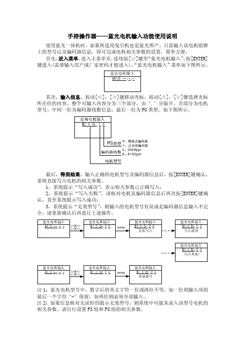
使用蓝光一体机时,如果所选用曳引机也是蓝光所产,只需输入该电机铭牌上的型号以及编码器信息,即可完成电机相关参数的设置,简单方便。
首先,进入菜单。
进入主菜单页,连续按[∨]键至“蓝光电机输入”,按[ENTER]键进入(需要输入用户或厂家密码才能进入)。
“蓝光电机输入”菜单如下图所示。
其次,输入信息。
按动[<],[>]键移动光标,按动[∧],[∨]键选择光标所在位的内容。
整个可输入内容分为三个部分,由‘.’分隔开。
首部分为电机型号,中间一位为编码器线数信息,最后一位为PG 类型。
如下图所示。
1
22048ppr
88192ppr
最后,得到结果。
输入正确的电机型号及编码器信息后,按[ENTER]键确认,系统直接写入电机的相关参数。
1,系统提示“写入成功”,表示相关参数已正确写入;
2,系统提示“写入失败”,请核对电机及编码器信息后再次按[ENTER]键确认,直至系统提示写入成功;
3,系统提示“无效型号”,则输入的电机型号有误或是编码器信息输入不完全,请重新确认后再进行上述操作。
注1:蓝光电机型号中,数字后的英文字符一位或两位不等,如一位则输入项的最后一个字符‘-’保留,如两位则必须全部输入。
注2:如果信息核对无误但仍提示无效型号,则系统中可能未录入该型号电机的相关参数,请自行设置F5组和F8组的相关参数。
东方电子 1200W 开关模式电源 1235CE 安装和操作手册说明书

REGULATED DC POWER SUPPLY MODEL: SEC-1235CEPlease read this manual before operating your power supply.TABLE OF CONTENTSTopic PageImportant safety instructions2Description and features3Operation from AC iput voltage of 230 VAC3Connections and operation4Cooling fan control / thermal protection4Battery charging and battery back up5Trouble shooting6Limiting electromagnetic interference7Switching power supplies & RF noise 8,9,10 Specifications 11 Warranty 12RISK OF ELECTRIC SHOCKDO NOT OPENWARNING—TO REDUCE THE RISK OF FIRE OR ELECTRIC SHOCK, DO NOT EXPOSE THIS APPLIANCE TO RAIN OR MOISTURE. THERE ARE NO USER SERVICEABLE P ARTS INSIDE—REFER TO QUALIFIED SERVICE PERSONNEL.IMPORTANT SAFETY INSTRUCTIONSPlease read before using your power supply.1) It Is recommended that you return your power supply to a qualified dealer for any service or repair. Incorrect assembly may result in electric shock or fire.2) To reduce the risk of electric shock, unplug the power supply from the outlet before attempting any maintenance or cleaning. Turning off controls will not re-duce this risk.3) If an extension cord is used, make sure that it has grounded male plug Type EU1-16P (CEE-7/7, “Schuko”) and grounded female receptacle(s) Type EU1-16R (CEE-7/4, “Schuko”). The size of the current carrying conductors should be such that they are able to carry at least 5 A for the length of the extension.4) Place the unit in an area that will allow air to flow freely around the unit. DO NOT block or obstruct vent openings on the side/bottom of the unit.5) Keep the unit away from moisture and water.6) NEVER OPERATE THE UNITS IN PARALLELWARNING! Your power supply should be grounded to reduce the risk of electric shock. The power supply comes with a detachable power cord that has a grounded male plug Type EU1-16P (CEE-7/7, “Schuko”). The flat contact strips on the circumference of the plug get connected to the chassis of the unit. When the power cord is plugged into the corresponding receptacle Type EU1-16R (CEE-7/ 4, “Schuko”), the chassis of the unit is automatically connected to the earth ground through the equipment grounding conductor that is connected to the spring con-tacts of the power outlet receptacle Type EU1-16R (CEE-7/4, “Schuko”).The power cord must be plugged into a Type EU1-16R (CEE-7/4, “Schuko”) outlet that is properly installed and grounded in accordance with all local codes and ordinances. Never alter the power cord that has been provided. If the plug of the cord will not fit the outlet, have a proper outlet installed by a qualified electrician. Improper connection can result in risk of electric shock.DO NOT USE THE POWER SUPLY FOR DIRECT CHARGING OF BATTERY OR DI-RECT CONNECTION TO A BATTERY FOR BATTERY BACK-UP. (Please read the section on “Battery Charging and Battery Back-up” on page 5).2.SEC-1235CE is a Switched Mode Power Supply (SMPS) which converts 230 V, 50 Hz AC power to regulated 13.8 V DC power based onPulse Width Modulation (PWM) control.•Based on switched mode technology and PWM control•Compact and light weight•High efficiency and less heat dissipation•Protected against short circuit, over load and over temperature•Cooling by temperature controlled fan•Safety compliance to European Low Voltage Directive 2006/95/EC •EMI/EMC compliance to European EMC Directive 2004/108/EC3.4.NOTE : The DC output connectors (RED + and Black -) have a tubular hole of diameter 0.2” (5mm) with a set screw. If bare wire with stranded conductors is used to connect the load to the above output connectors of the power supply, the strands will spread out as the set screw is tightened and hence, the set screw will not pinch all the strands. As a result, the effective cross section of the current conducting area of the wire will be reduced resulting in voltage drop at the load end, reduced efficiency and also overheating. For a firm connection, crimp / sol-der a suitable pin type of copper terminal on the wire end to be connected to the power supply. For convenience, a pair of terminals has been provided for crimp-ing / soldering to the wire end.OPERATION• Ensure that the on / off switch on the power supply is switched off and it is un-plugged from the AC outlet • Switch off the 12 V load to be connected to the power supply. Connect the positive input wire of the load to the RED (Positive) terminal of the power supply and the negative input wire of the load to the BLACK (Negative) terminal of the power supply. Ensure that the connections are secure and tight • Plug the power supply into the AC outlet. Press the On / Off switch of the power supply to the On position and check that the switch is illuminated indicating availability of the AC input power. If the On / Off switch is not illuminated, recheck the AC input connection, AC outlet and the fuse inside the power supply.• Now switch on the DC load • Ensure that the continuous load is limited to 30 AWARNING! Operate the unit in a well ventilated, open and cool area. Do not block the openings at the fan discharge on the bottom of the unit and the suction openings on the sides.The units are cooled by convection and by forced air cooling. A temperature controlled fan has been provided to improve cooling at higher loads and at higher ambient temperatures. The switching on of the fan is controlled by a sen-sor mounted on the power transformer. The fan will be switched on when the temperature of the sensor reaches 60° C +/- 5° C. The fan will be automatically switched off when the sensor cools down to 50° C +/- 5° C. Thus, at lower loads or during lower ambient temperatures, the fan may remain switched off.An additional protection is provided to shut down the power supply in case the fan fails or if the air flow is blocked or if the ambient temperature is very high. A second temperature sensor is also mounted on the power transformer and will activate at 105° C +/- 5° C and shut down the output of the power supply. After the power supply cools down to 95° C +/- 5° C, the temperature sensor will de-activate and the power supply will resume operation automaticallyThe output voltage can be adjusted with the help of the internal potentiometer marked “VR2”. Adjustment range is (11V to 16 V).WARNING! At output voltages higher than 13.8 V, the maximum output current should be reduced linearly from 30 A at 13.8 V to 25 A at 16 V.OVERLOAD / SHORT CIRCUITThe units are protected against overload by constant current limiting at 35 A. If the load tries to draw more than 35A, the output voltage will drop and will no longer be regulated. The output voltage will drop to near 0 V in case of a dead short. The unit will recover automatically once the overload condition is removed.OVER TEMPERATUREProtection is provided to shut down the power supply in case the fan fails or if the air flow is blocked or if the ambient temperature is very high. A temperature sensor is mounted on the power transformer and will activate at 105° C +/- 5° C and shut down the output of the power supply. After the power supply cools down to 95° C +/- 5° C, the temperature sensor will de-activate and the power supply will re-sume operation automaticallyWARNING!These units are power supplies and not battery chargers.Do not connect these units directly to a batteryThe voltage of a 12 V battery in a deep discharged condition will be around 10 to 11.4 V. When a deeply discharged 12 V battery is charged at say 13.8 V, it will initially draw a very large current. As the battery capacity is restored, the battery voltage increases to around 13.8 V when fully charged and the current drawn by the battery reduces a few hundred mA.If a deeply discharged battery is directly charged by SEC-1235CE, the battery will initially draw a very large current and thus, will force the power supply into current limit mode for prolonged period of time. This is harmful for the power supply as operating under prolonged periods under current limit conditions is an abnormal operating condition.SEC-1235CE may be used for battery charging and battery backup application only when the battery is charged through a suitable external isolating diode and charge limiting resistor in series with the power supply. The isolating diode will ensure that the battery does not feed power back into the power supply and the series connected charge limiting resistor will limit the maximum charging current to a value less than the current limit.It is recommended that the optional Battery Backup Module BBM-12100 may be used in conjunction with the power supply for battery charging / backup application.Call Technical Support at 1-800-561-5885 for further assistance5.PROBLEM : Power ON/OFF switch does not illuminate when turned on.PROBABLE CAUSE SUGGESTED REMEDYNo power in the AC outlet Check there is power in the outlet.AC side fuse inside the power Replace the fuse inside the unit. supply is blown See fuse ratings at page 11PROBLEM : AC side fuse blows as soon as power is turned on.PROBABLE CAUSE SUGGESTED REMEDYUnit is defective Call technical support. PROBLEM : The output voltage is 0 V or very lowPROBABLE CAUSE SUGGESTED REMEDYInput voltage is very low Check that the input voltage is230VACThe unit is in current limit condition Check the output terminals are not due to overload caused by large reactive shorted. Remove the load. If the loading or by the output being short output voltage gets restored, the circuited load is shorted or is offering largereactive impedance.Unit is shut down due to over Check that the fan has not failed or temperature.the vent openings are not blockedPROBLEM : Output voltage drops as soon as the load is switched on PROBABLE CAUSE SUGGESTED REMEDYThe unit is going into current Reduce the load currentlimit protection mode to less than the current limit value.Motors, pumps, compressors,relays, incandescent and halogenlamps and large capacitors in theinput section of the DC devicesdraw very high inrush or startingcurrents of up to 10 times theirnormal operating currents. Ensurethat these inrush/starting currents6.This equipment has been tested and found to comply with the limits as laid down under European Standards EN55022 (Class-B) & EN610000-3 - 2 & 3. These limits are designed to provide reasonable protection against a harmful interference in a residential installation. This equipment generates, uses and can radiate radio frequency energy and, if not installed and used in accor-dance with the instructions, may cause harmful interference to radio commu-nications. However, this does not guarantee that interference will not occur in a particular installation. If this equipment does cause harmful interference to radio or television reception, which can be determined by turning the equip-ment off and on, the user is encouraged to try to correct the interference by one or more of the following measures:•Reorient or relocate the receiving antenna.•Increase the separation between the equipment and receiver.•Connect the equipment into an outlet on a circuit different from that to which the receiver is connected.•Consult the dealer or an experienced radio / TV technician for help.7.1. Switched mode power supplies ( SMPS ) employ high frequency switch-ing and thus, are a source of radio interference, a recipient of radio interfer-ence and a conduit of radio interference. ( Older linear type transformer based power supplies do not employ high frequency switching voltages and will be quieter as compared to switching type of supplies).2. The primary emission sources originate in the switching devices due to their fast switching current transitions: harmonics of the switching frequency and broadband noise created by under-damped oscillations in the switching circuit. The secondary source is from the bridge rectifier, both rectifier noise and diode recovery. The AC input rectifier / capacitor in the front end of the switching power supplies ( excepting those with power factor correction ) are notorious for generating power supply harmonics due to the non linear input current waveform. The noise is both conducted and radiated through the input power cord and the DC output wiring to the radio.3. Switching power supplies are also recipients of radio interference. The normal operation of the power supply can be disturbed due to RF noise getting coupled into the power supply. Thus, the power supply may generate excessive RF noise and lose output voltage regulation due to excessive trans-mitter energy being coupled through the AC / DC lines to the power supply’s regulator feedback path. This may be due to antenna being too close or due to the antenna or feed system not radiating properly. First check the antenna system SWR. Then, if necessary, relocate either the antenna or the power supply farther apart.4. The receiver may “hear” the power supply. A slowly moving, slightly buzz-ing carrier heard in the receiver may be caused by the antenna being too close. As with the transmitter related noise pick up, a loose coaxial connec-tor or a broken or a missing ground may aggravate this problem. Normally these noises will be below the background or “band” noise. Increase the separation between the power supply and the receiving antenna. Use an outdoor antenna. This will reduce the amount of signal picked up from the power supply and also increase the amount of the desired signal.8.5. The conducted and radiated noises are limited as per the applicable na-tional / international standards. In North America, the applicable standard is as per FCC Part 15(B) for Class “B” digital devices. The European standard is as per EN55022, Class “B” & EN610000-3-2, 3. Thus, the RF interfer-ence is limited but not entirely eliminated.6. The conducted RF noise from these power supplies is limited to the maxi-mum allowable levels by internal filtration. The filtered RF noise currents (normally < 5mA ) are bypassed to the chassis of the power supply. The chassis is, in turn, connected to the earth ground pin of the AC input power cord (for Class 1 units). Thus, the filtered noise currents are intentionally leaked to the earth ground. This is termed as the “Earth Leakage Current”. For safety against electric shock, this earth leakage current is also required to be limited. It will be seen that these two requirements are conflicting. NOTE: In some cases, to prevent electric shock hazard due to abnor-mal leakage current (like in marinas, spas, hot tubs, wet spaces etc.), the AC outlet circuits / receptacles in these areas are served through a GFCI (Ground Fault Circuit Interrupter ). This GFCI is normally set to trip when it senses an earth leakage current > 5 mA. A single GFCI may be serving multiple AC outlet circuits / receptacles and therefore, will be sensing the sum of all the leakage currents of the devices connected to these. As the switching power supplies have intentional leakage current as explained above, it may trip a GFCI feeding multiple AC outlet circuits / receptacles. In such cases, disconnect devices connected to the other AC outlet circuits / recep-tacles served by this GFCI.9.7. Following additional guidelines may be followed to reduce the effects of RF noise:e additional appropriate AC radio frequency interference (RFI)power line filter rated for minimum 5 A immediately before the ACinput of the power supply. For example, consider suitability ofmodel # 6VN1 from “N” series by Corcom, Inc. () orsimilar. Filtered, ferrite coated cord set ( ) isanother choice. These cord sets, with integral line interferencefilters, reduce common and differential mode interferences over awide frequency range. Because they are shielded, they are alsoeffective against radiated interferences. In addition to the built-infilter networks, the cable conductors are coated with an RF ab-sorbing ferrite compound. This provides additional attenuation athigh frequencies that is lacking in most regular LC filters. The RFabsorption of the ferrite-coated cable avoids resonances at highfrequencies, reducing the conducted and radiated RF noises evenfurthere additional appropriate DC radio frequency interference (RFI)power line filter rated for minimum 40 A immediately after the DCoutput of the power supply. For example, consider suitability ofmodel # “FD10B050” from “FD” series by Curtis Industries() or similar.c.Twist the positive and negative wires from the output of the powersupply to the radio.d.The DC side positive and negative outputs of these power sup-plies are isolated from the chassis. As explained at paragraph 6above, the noise currents are filtered to the chassis ground andthe chassis ground is connected to the earth ground through theearth ground pin of the AC power outlet receptacle. Avoid con-necting (referencing) the DC negative output terminal of the powersupply to the earth ground.e.Connect a 1/4” wave length of wire on the negative terminal of thepower supply. Connect one end of the wire to the negatvie termi-nal and leave the other end free. The wave length corresponds tothe wave length of the interfering frequency. (May not be practicalfor long wave lengths).[ Formula: Wave length (Meters) = 300 / frequency in MHz ]10.Model No.SEC-1235CENominal Input Voltage230 VAC, 50Hz (Range: 207 to 253 VAC)Input current 3.5 A at 230 VACOutput Voltage13.8 VDCOutput voltage adjustment11.5 V to 15.5 V with the help of internal potentiometer Output current30 A continuousCurrent limit35 A, constant current limiting, auto recoveryNo load current draw130 mA at 230 VAC, 50 HzRipple50 mV peak to peakNoise150 mV peak to peakPeak Efficiency85%Cooling Temperature controlled fanProtections against Overload, short circuitOver temperatureOperating temperature0° to 40° CSafety compliance Comforms to European Low Voltage Directive 2006/95/EC • Standards• IEC 60950-1; EN 60950-1EMI/EMC compliance Comforms to European EMC Directive 2004/108/EC • Standards• EN 55022 (class B); EN 61000-3-2; EN 61000-3-3• EN 55024 :EN 61000-4-2 to 6; EN 61000-4-8; EN 61000-4-11 AC input connections Male AC inlet connector Type “IEC 320-C14”Detachable AC power cord with:• Female connector Type “IEC 320-C13” on one end tomate with AC power inlet connector on the power supply• Male, 2 pole, 3 Wire grounding plug Type EU1-16P(CEE 7/7) (Schuko) on the other end for connection to theAC outlet.DC output connections RED (+) and BLACK (-) terminals with tubular hole and setscrew. Hole diameter 0.2 “, (5 mm). Includes a pair of copper terminal lugs for crimping to output wires to the load Input side fuse250V, 4 A(5 mmX20mm, glass ferrule,Manufacturer: Ltttel Fuse, Model 218004delayed action)Weight 3.4 lbsDimensions (L X W X H)8” X 7.3” X 2.5”Note:The above specifications are subject to change without notice11.SEC-1235CE manufactured by Samlex America, Inc. (the “Warrantor“) is war-ranted to be free from defects in workmanship and materials under normal use and service. This warranty is in effect for 3 years from the date of purchase by the user (the “Purchaser “)For a warranty claim, the Purchaser should contact the place of purchase to obtain a Return Authorization Number.The defective part or unit should be returned at the Purchaser’s expense to the authorized location. A written statement describing the nature of the defect, the date of purchase, the place of purchase, and the Purchaser’s name, address and telephone number should also be included.If upon the Warrantor’s examination, the defect proves to be the result of defective material or workmanship, the equipment will be repaired or replaced at the Warrantor’s option without charge, and returned to the Purchaser at the Warrantor’s expense.No refund of the purchase price will be granted to the Purchaser, unless the Warrantor is unable to remedy the defect after having a reasonable number of opportunities to do so.Warranty service shall be performed only by the Warrantor. Any attempt to remedy the defect by anyone other than the Warrantor shall render this warranty void.There shall be no warranty for defects or damages caused by faulty installation or hook-up, abuse or misuse of the equipment including exposure to excessive heat, salt or fresh water spray, or water immersion.No other express warranty is hereby given and there are no warranties which extend beyond those described herein. This warranty is expressly in lieu of any other expressed or implied warranties, including any implied warranty of mer-chantability, fitness for the ordinary purposes for which such goods are used, or fitness for a particular purpose, or any other obligations on the part of the Warran-tor or its employees and representatives.There shall be no responsibility or liability whatsoever on the part of the Warrantor or its employees and representatives for injury to any persons, or damage to person or persons, or damage to property, or loss of income or profit, or any other consequential or resulting damage which may be claimed to have been incurred through the use or sale of the equipment, including any possible failure of mal-function of the equipment, or part thereof.The Warrantor assumes no liability for incidental or consequential damages of any kind.Samlex America Inc. (the “Warrantor”)110-17 Fawcett RoadCoquitlam BC V3K6V2 Canada(604) 525-383612.Notes:Attach copy of receipt here:Version SEC1235CE(Nov2007)Thank you purchasing a Samlex power supply product!。
H62Z1235PDC-MP说明书
H62Z1235PDC-MP说明书1、设定H62Z1XXXXPDC-MP的参数H62Z1XXXXPDC-MP在设置菜单中会提供多种设定参数,有图像分辨率、光圈、聚焦方式、快门等。
H62Z1XXXXPDC-MP要进行图像分辨率的设置。
大为H62Z1XXXXPDC-MP有多种参数设置,每次拍摄前都要检查相机的设置菜单,这样才能确认分辨率、快门等参数有没有设置好。
没设置好的话拍出的照片效果不会很理想。
注:设置H62Z1XXXXPDC-MP的分辨率,要调到最高分辨率这一档。
H62Z1XXXXPDC-MP的使用方法2、尽量使被拍对象主体充满取景框为了效果更好,在使用H62Z1XXXXPDC-MP时要选择最高分辨率,同时让被拍对象主体充满取景框。
若你只要拍摄一个单独的对象,例如一个手术部位,一个标本,要将被拍对象主体充满取景框内。
H62Z1XXXXPDC-MP的使用方法3、正确运用光照度和闪光灯由干H62Z1XXXXPDC-MP是中内置图像传感器(CCD芯片)拾取图像的,所以要有合适的光照才能拍出很好的效果。
要创造光照好的环境来拍照,由于CCD芯片的特点,照片的色调和色彩质量会依赖光照强度的。
光照太强或太弱都是不行的。
一般的H62Z1XXXXPDC-MP都设有内置闪光灯,可以分为四档:闪光、不闪光、防红眼闪光和自动闪光。
自动闪光这一档是由相机对被拍对象光照度的检测,看看是不是需要补充光线。
闪光灯容易被周围附近的物体反射回来,可能会在照片上形成一些光斑。
H62Z1XXXXPDC-MP的使用方法4、色温的调节彩色胶卷有日光型和灯光型两种,日光色温是5400K,灯光色温是3200K。
H62Z1XXXXPDC-MP用CCD芯片作为传感器,是没有光源类型之分的,但为了适应不同的光源环境,可以采用白平衡调节方法来校正照片的色温。
H62Z1XXXXPDC-MP的白平衡调节有手动和自动两种模式,而手动调节具有更多的灵活性,这样才能创造出更好的艺术效果。
MP3使用说明书
使用说明书:
1.开机操作:将开机按钮打到(ON)上,如果指示灯在闪烁,表示正在播放,如果只亮不闪,将MP3冲电后再重复上面步骤!
2.关机操作:将开机按钮打到左边即可关机,指示灯灭。
3.音量调节:长按“+”字按钮,便可调大音量,长按“-”字按钮,便可减小音量!4.下一首:轻轻的按“+”字按钮,反之上一首。
5.指示灯:播放状态—灯闪烁,在充电状态下,充电时灯亮。
6、连接电脑:使用MP3自带的USB线和电脑连接起来,等弹出移动盘符后,可以进行考入、删除文件等操作。
操作完时请不要直接拔除MP3,应该到电脑右下角,点删除硬件先再拔出。
注意事项
1、连接电脑USB接口充电或用充电器给MP3充电时务必开机(ON)状态充电,不需要关注指示灯的状态,充电时间不要超过2个小时左右,否则极易造成MP3内置锂电池的失效和损坏。
2、单次连接在电脑USB口上的时间也不要超2.5个小时,MP3从电脑上拔出来的时候,一定要严格按照电脑操作系统的要求,先“安全删除硬件”后再拔下MP3。
否则极易造成MP3播放器丢失软件程序。
3、新机正常使用中,请不要对MP3播放器进行格式化或者固件升级。
全自动软管贴标机说明书中文(1)
RGTB-60B全自動软管贴标机使用說明書目录:一、设备概述二、工作原理三、操作界面说明四、调试与安装五、光电开关调节说明六、故障分析及解决方法七、日常维护及注意事项八、电气接线图九、设备参数表十、附录:伺服参数表一、设备概述全自动软管贴标机经过本公司近十年的研究,率先采用日本公司先进技术,真正达到完美贴标。
贴标系统具有学习功能,可自动测出产品和标签的尺寸,利用CPU 的高速运算功能使标签与产品的中心线完全吻合,精度大幅提高。
传动系统采用高精度的OMRON伺服系统实现系统的高响应,和极高的可靠性。
整机零部件采用独特的表面处理技术,永不生锈。
二、工作原理1、系统通电,按下运行按钮,转盘不动,等待自动下料斗下料,料被下到料斗,在定位开关的时候,软管被测物电眼检测到有产品,此时滑动气缸将软管推到模具上面,滑动汽缸上面的磁性开关检测到滑手将软管推到位,此时转盘转一格到位停下,标头开始送给一张标签,同时滑动气缸滑块退回,滑块被后面的磁性开关检测退回到位,又开始进行下一次自动上料;转盘每走一下,下料气嘴都吹一次以完成下料;2、按下定位开关,让定位开关打开,产品被测物电眼看到,同时色标电眼也能检测到色标标记,标头就开始送给一张标签;三、操作界面说明接通电源,打开总开关,显示主画面:点击主画面进入如下画面:按下键进入另一系统界面:一)画面操作说明:画面上边显示为出标参数,意义分别如下:1、标签速度:进给标签的速度,可通过触及参数区输入,数值范围:0-40m/min:2、标签伸出量:标签伸出及停止标签的位置,可通过触及参数区输入。
数值范围0.0 –999.0mm。
3、标签延时:贴标延时,即当色标电眼检测到被贴物后,等待一定时间才开始贴标,以确保标签贴到正确的位置。
可通过参数区输入,数值范围:0-1000ms。
4、下管吹气:下管吹气时间可通过触及参数区输入,数值范围:0-999ms。
5、参数设置好以后按“手动”按钮,出现“手动操作”画面,进行测试:按下“贴标测试”按钮,系统将进给一张标签,可据此查看设定出标参数是否合适。
T4 系列使用手册说明书
I T4 系列使用手册
Ver:1.0
5.2.4 测试打印...........................................................................................44 5.2.5 内存...................................................................................................44 5.2.6 表格...................................................................................................44 5.2.7 警告讯息...........................................................................................45 5.2.8 打印机状态.......................................................................................46 6. 故障排除 ................................................................................................................47 6.1 液晶屏幕错误讯息......................................................................................47 7. 規格 ........................................................................................................................48 7.1 T4+系列規格................................................................................................48 7.2 通用序列总线(USB)接脚图.......................................................................50 7.3 串行端口脚位图..........................................................................................51 7.4 以太网络脚位图..........................................................................................51
1235 用户手册-V2.0
用户手册使用指南用户手册使用指南下一页介绍AutoDELFIA全自动时间分辨荧光免疫分析仪的开机和程序启动。
如果您负责本系统的管理,请参阅本文第60页相关功能的介绍,以帮助您准备常规操作的软件,比如:选择测试项目,定义数据流以及个性化系统设置等。
如果您是一位对本系统还不十分熟悉的常规操作人员,请参阅本文第5页的开始部分有关如何使用基于Windows的操作系统的小技巧。
常规使用请参阅本文第8页的开始部分“操作指南”。
本章节包括多个部分,每部分分别介绍AutoDELFIA全自动时间分辨荧光免疫分析仪的一项主要功能。
综合这些操作即为获得测试结果的必要步骤。
“自动操作”功能可用于链接这些操作步骤,从而使您的工作达到最佳次序的效果。
有关“需要预处理的分析实验”的介绍请参阅本文第73页。
第81页“其它功能”按字母顺序介绍AutoDELFIA全自动时间分辨荧光免疫分析仪的一些次要功能。
第89页“术语表”解释一些您可能不太熟悉的术语。
本文中,您会注意到部分用语标有下划线,它们可以帮助您在“其它功能”或“术语表”中找到更多的相关信息。
本文中,凡是电脑屏幕上需要鼠标点击的按钮(即移动光标至屏幕按钮上方,点击鼠标左键),均以粗黑体文字标记。
凡是仪器或键盘上需要用手指点击的按钮,均以粗黑斜体文字标记。
有关新生儿筛查的操作介绍请参阅单独的新生儿筛查用户手册。
有关系统维护的操作介绍(主要见于“维护保养”菜单),请参阅单独的维护保养用户手册。
另外,还有一本手册用于历史浏览器。
所有上述手册均包含在本用户手册包中。
有关AutoDELFIA全自动时间分辨荧光免疫分析仪的更详细资料,请参阅仪器说明书。
有关试剂盒的资料,请参阅各测试物试剂盒说明书。
有关本系统的简明操作规程,请参阅常规操作流程表。
仪器说明书内附的“样品装载黄金规则”可以帮助您的实验室制定操作规程。
1开机开机开启电源如果AutoDELFIA全自动时间分辨荧光免疫分析仪尚未开机,请依次进行:1. 开启AutoDELFIA样品处理器电源开关;2. 开启AutoDELFIA反应板处理器电源开关;3. 开启打印机电源开关;4. 开启电脑显示器电源开关(如果有独立的电源开关);5. 开启电脑主机电源开关;6. 启动系统程序;7. 等待大约30分钟,系统主体部分预热完成;8. 从“选项(Options)/显示温度(Show Temperature)”菜单查看反应板处理器温度,一般需2.5小时预热。
- 1、下载文档前请自行甄别文档内容的完整性,平台不提供额外的编辑、内容补充、找答案等附加服务。
- 2、"仅部分预览"的文档,不可在线预览部分如存在完整性等问题,可反馈申请退款(可完整预览的文档不适用该条件!)。
- 3、如文档侵犯您的权益,请联系客服反馈,我们会尽快为您处理(人工客服工作时间:9:00-18:30)。
OKS1275使用说明书
一.引脚排列及性能简介
PIN描述
(Low Enable)
(Low Enable)
Enable(Low Enable)
带软件口令的非易失性存储器OKS1275在引脚排列上与普通SRAM,
EEPROM及通用NVRAM无异,只是它在通用NVRAM即由锂电池及抗干扰电路和SRAM组成的基础上在写信号上增加了软件锁功能。
当用户要向此SNVRAM内存入数据时,先要打开写信号上的锁开放片内写信号,此指令为向此芯片最后一个单元写入88这个数(此时88并未真的存入此芯片的最后一个单元,这只是一个开锁指令),而当用户写完数据后,再向最后一个单元写入非88的数即可将写信号锁死,任凭外部干扰怎样也不能打开写信号,从而达到可靠保存数据的目的。
同时原来通用NVRAM保存数据的功能即由监测电路监视V CC,当其上下电≤4.35V时自动拉高片内片选信号,使数据自动保护的功能此SNVRAM一样具备。
二、读取模式
OKS1275在WE(写使能)被禁止(high)且CE(片选)被选中(Low)并且OE(读信号)被使能(Low)执行一次读循环。
20个地址输入线(A0-A19)指定的唯一的地址定义将要被访问。
最后输入信号稳定后8位数据输出驱动器将在t ACC时序内得到有效数据。
三、写模式
要向OKS1275写数据,就先要打开放写信号,这就需要先发出一个向OKS1275最后两个字节即最高字节写入88的指令。
在写信号开放后,片内SRAM的写信号随外部写信号引脚的变化而变化,否则片内写信号被置高不能写入数据。
在写信号开放后,地址输入稳定后,OKS1275在WE和CE
信号处于激活(低电平)状态为写模式。
最后出现的CE或WE下降沿将决定写循环的开始,写循环终止于CE或WE前边的上升边沿。
在写循环内所有地址输入必须保持有效。
在下一个循环能被初始化前,WE写信号必须将高电平保持最少记录时间(t WR).写循环期间OE控制信号应当保持失效(高电平),避免总线冲突,如果输出总线已经有效(CE和OE激活),则写信号可以在t ODW时序内从下降边沿开始禁止输出。
四、数据保存模式
OKS1275为Vcc提供全部功能,当V CC大于4.5伏或4.75伏,写保护为4.35伏或 4.75伏。
当Vcc掉电时保存数据,没有任何附加支持电路的需要。
HK1275通常监视Vcc。
如果电源电压降低,RAM自动写保护其本身。
所有对RAM的输入变为“不接收”,所有输出为高电阻。
当Vcc降低到大约
3.0伏时,电源转换电路将用锂电源向RAM供电保存数据。
电压升高时,
当Vcc升高到大约3.0伏时,电压转换电路将外部Vcc与RAM连接。
正常RAM操作在Vcc超过4.5伏或4.75伏后能够重新开始。
同时OKS1275还提供了软件锁死功能,即在用户完成写入数据的操作后,只需向该芯片最后一个单元写入一个非88的数,如99,03等,片内SRAM的写信号被锁死,不论外部写信号怎样都不能向片内存入数据,从而大大提高了芯片的可靠性。
五、出厂状态及运输
OKS1275从宏空半导体出厂均保证满电量。
运输及使用中的重力加速度不应超出1.5G否则影响寿命。
六、验收及服务
本产品验收期为1个月即自客户得到本产品后对以下各项性能指标进行验收,如果异议应在1个月内提出更换或退货。
质量保证期即服务期为一年,如产品在一年内非使用问题而产生的产品质量问题并且未经使用损坏的经我公司检验认可可以给予更换。
我公司拥有对以上条款的最终解释权。
七、各项指标
①最大范围
各脚对地电压-0.3~5.0V
储存温度-40℃~70℃
焊接温度200℃不能超过5秒
操作温度0℃~55℃准工业级0℃~70℃
工业级-40℃~70℃
注:长期暴露在工作在以上最大范围下将影响使用周期
⑤建议电源上下电时间
注:请技术人员在使用前仔细阅读英文资料,中文翻译仅为全部资料中的一部分。