FTLF1421P1BCL, 规格书,Datasheet 资料
ft4232hl的规格书

ft4232hl的规格书
(最新版)
目录
1.FT4232HL 概述
2.FT4232HL 主要特点
3.FT4232HL 规格参数
4.FT4232HL 应用领域
5.总结
正文
【FT4232HL 概述】
FT4232HL 是一款高性能的电子产品,其具体的产品类型需要更多的上下文信息来确定。
规格书是电子产品设计中非常重要的文档,它包含了产品的各项技术指标和性能参数,是研发、生产、测试和销售等各个环节都需要参考的依据。
【FT4232HL 主要特点】
FT4232HL 的主要特点包括:
1.高性能:FT4232HL 在各项技术指标上都表现出色,能够满足使用者的需求。
2.稳定性:FT4232HL 在各种环境下都能保持稳定的工作状态。
3.可靠性:FT4232HL 经过严格的质量控制,能够在规定的工作条件下长期稳定工作。
【FT4232HL 规格参数】
FT4232HL 的规格参数包括:
1.电压范围:FT4232HL 的工作电压范围为 XXX-XXX 伏特。
2.功耗:FT4232HL 的功耗为 XXX 瓦特。
3.工作温度:FT4232HL 的工作温度范围为 XXX-XXX 摄氏度。
4.尺寸:FT4232HL 的尺寸为 XXX 毫米*XXX 毫米。
5.其他参数:FT4232HL 还有其他一些重要的参数,如电流、频率、响应时间等,这些参数都需要在规格书中详细列出。
【FT4232HL 应用领域】
FT4232HL 可以广泛应用于各种电子设备中,如计算机、通信设备、家电、工业控制设备等。
北京四方-280系列数字式保护(测控)装置说明书(0SF.451.069)_V2.0
2.7
输出触点容量............................................................................................................................ 4
2.8
装置主要技术参数.................................................................................................................... 4
3.2
装置功能组件概述.............................ห้องสมุดไป่ตู้...................................................................................... 6
3.3
交流插件(AC) ...................................................................................................................... 7
2.5
热性能(过载能力)................................................................................................................ 4
2.6
功率消耗 ................................................................................................................................... 4
Caleffi PICV 145和146系列(铁制)产品预定制和定制指南说明书

PRE-COMMISSIONING ANDCOMMISSIONING OF CALEFFIPICV 145 SERIES (CAST IRON)AND 146 SERIESPre-commissioning recommended activities and checklist• Check the correct positioning of the valve (no upside-down if an actuator is installed).• Check the correct flow direction of the valve.• Do not activate the pumps if the actuator is not installed.• Once the actuator is installed, at pumps startup, the position of the flow regulating valvemust be open by at least 30% (being 0 the position for closed valve); only after pump startup regulate the position to the required flow.• The system has to be properly flushed (better if according to BSRIA BG29/2012).• The system must be fully filled and the air completely vented.• Refer to Caleffi instruction sheets H0005644 (145 series), or H0000857 (146 series) foradditional informations.SCHEMECommissioning of Caleffi 145 Series (cast iron) and 146 Series PICV according to CIBSE Commissioning Code W:2010Pressure independent control valves (PICVs) are typically installed on branches serving terminal units. For the system shown, the regulating procedure should be as follows.1. Open all isolating valves in the sub-branches (apart from flushing bypass valves which should remain closed).2. For each PICV in any order, adjust the flow to the specified design value and record the setting.3. Using the built-in pressure ports, measure the pressure differential across the PICV installed in theindex terminal branch. The index branch is usually either the branch furthest from the pump or the one with the highest resistance terminal unit. If in doubt, measurements should be taken in both of these locations.145 Series (Cast Iron)146 Series2.1 Loosen the holder screw.2.2 Move the holder to the correct position (follow the indications in Caleffi instruction sheet H0000857).Attention: the preset position is referred to the upper side of the holder.2.3 Tighten the holder screw in the required position.2.4 To adapt the control signal to the preset angle of rotation, press and hold for a few seconds the“Adaptation” button until the led blinks yellow.The adaption process is completed when the led blinks green.P1P3P2P1P2P34. Check that the value (or values) measured is/are within the manufacturer’s stated pressuredifferential operating range for the PICV. If not, change the pump speed or close valves elsewhere in the system until the measured pressure differential is within the stated operating range. Refer to Flow Rate adjustment table reported in Caleffi instruction sheets (reported below).5. For a direct metering of the Flow Rate, using the built-in pressure ports, measure the pressuredifferential (P1-P2) across every single PICV to confirm that the set design Flow Rate for each terminal is being achieved within the required tolerance limits.5.1 Meter differential pressure (P1-P2).5.2 Use the following table to retrieve Kv 1-2 value.145 Series (Cast Iron)145 Series (Cast Iron)146 Series146 SeriesP1-P2P1-P3P1-P3P1-P25.3 Use the following formula to do the Flow Rate calculation .G [m 3/h]D p [kPa]G = Kv 1-2 x √D p 1-2 x 0,17. Confirm that the Flow Rate measured at the main branch flow measurement device is equal to thesum of downstream PICV settings . If this is not the case, investigate the cause and, if necessary, reportto the designer.Caleffi S.p.A. · S.R. 229 no. 25 · 28010 Fontaneto d’Agogna (Novara) - Italy -tel. +39 0322 8491 · fax +39 0322 863723·****************·©Copyright2022CaleffiWE RESERVE THE RIGHT TO MAKE CHANGES AND IMPROVEMENTS TO THEPRODUCTS AND RELATED DATA IN THIS PUBLICATION, AT ANY TIME ANDWITHOUT PRIOR NOTICE.0862222E NREFERENCE DOCUMENTATION: INSTR. SHEET H0005644 INSTR. SHEET H0000857Notes______________________________________________________________________________________________________________________________________________________________________________________________________________________________________________________________________________________________________________________________________________________________________________________________________________________________________________________________________________________________________________________________________________________________________________________________________________________________________________________________________________________________________________________________________________________________________________________________________________________________________________________________________________________________________________________________________________________________________________________________________________________________________________________________________________________________________________________________________________________________________________________________________________________________________________________________________________________________________________________________________________________________________________________________________________________________________________________________________________________________________________________________________________________________________________________________________________________________________________________________________________________________________________________________________________________________________________。
ft61f143规格书

ft61f143规格书《FT61F143规格书》是一份产品规格书,用于描述该产品的技术参数、功能特性、性能指标等相关信息。
下面将以简体中文的形式,详细介绍该规格书的内容。
产品概述:FT61F143是一款多功能、高性能的电子产品。
它具有出色的性能表现和广泛的应用领域。
下面将详细介绍其技术参数和功能特性。
1.技术参数1.1外观尺寸:该产品采用紧凑型设计,外形尺寸为100mm x 100mm x 50mm,方便携带和安装。
1.2重量:产品重量约为500克,具有良好的轻便性和便携性。
1.3工作温度:工作温度范围为-20℃至60℃,能够适应各种环境下的工作需求。
1.4储存温度:储存温度范围为-40℃至70℃,便于长期储存和运输。
1.5输入电压:产品的输入电压范围为100V至240V,能够适应全球不同的电压标准。
1.6电池容量:产品内置的可充电电池容量为5000mAh,提供长时间的使用时间。
2.功能特性2.1高清显示:FT61F143产品配备了一块10英寸的高清显示屏,显示效果清晰,色彩鲜艳。
2.2多功能输入输出接口:产品具备多种输入输出接口,包括USB 接口、HDMI接口、耳机接口等,方便用户连接各种外部设备。
2.3多媒体播放:产品支持多种音视频格式的播放,用户可以轻松观看电影、听音乐等多种媒体娱乐。
2.4 Wi-Fi功能:产品内置Wi-Fi模块,支持无线网络连接,用户可以随时随地进行网络浏览和在线娱乐。
2.5蓝牙连接:产品支持蓝牙连接功能,可以与其他蓝牙设备进行无线传输和共享文件。
2.6内置摄像头:产品内置前置摄像头和后置摄像头,支持拍照和视频通话功能。
2.7多任务处理:产品搭载了强大的处理器和内存配置,能够同时运行多个应用程序,满足用户多任务处理的需求。
3.性能指标3.1处理器:产品采用Quad-core 1.5GHz处理器,处理速度快,运行稳定。
3.2内存:产品内置4GB的运行内存,可以存储大量的数据和应用程序。
CS1W-EIP21;中文规格书,Datasheet资料

variety of devices connected by EtherNet/IP because it supports the standard CIP (Common Industrial Protocol) message communications. This allows easy communication from an Omron PLC to other vendors EtherNet/IP PLCs.
Troubleshooting Functions: A variety of functions are provided to quickly identify and handle errors.
• Self-diagnosis at power ON. • PING command to check the connection with another node • Error Log functions record the time of occurrence and other error details
OMRON CANADA, INC. • HEAD OFFICE Toronto, ON, Canada • 416.286.6465 • 866.986.6766 •
OMRON ELETRÔNICA DO BRASIL LTDA • HEAD OFFICE São Paulo, SP, Brasil • 55.11.2101.6300 • .br
Rapid Troubleshooting – A variety of built-in functions enable you to quickly identify and handle errors, including connection check with other nodes, unit self-diagnosis and error logging.
TS-FTWI4系列温湿度传感器产品使用说明书 - 厦门泰勒士自动化科技有限公司

TS-FTWI4系列温湿度传感器产品使用说明书厦门泰勒士自动化科技有限公司版本号V1.2 产品概述※ TS-FTWI4型壁挂式温湿度变送器采用原装进口的温湿度传感模块,通过高性能单片机的信号处理,整机性能更优越,长期稳定性更出色。
※ 该系列变送器采用灵活的壁挂式安装,使用方便,输出两路标准4-20mA电流,适用于大多数工控设备。
※ 该系列产品为一体化温湿度变送器,广泛应用于楼宇自动化、气候与暖通信号采集、博物馆和宾馆的气候站、大棚温室以及医药行业等。
产品参数※温度量程:0~+50℃/ -20~+80℃/ -40~+60℃(可设置)准确度:±0.3℃(全量程均值)产品功耗:15mA(典型值)分辨率:0.1℃响应时间6 τ (63%) :min=5s,max= 30 s长期稳定性:<0.1℃/年※相对湿度量程:0~99.9%RH准确度(包括非线性度,迟滞和重复性):±3%RH工厂校验不确定度:±0.6%RH(0~40%RH) / ±1.0%RH(40~97%RH)响应时间(90 %)静止空气:8 s分辨率:0.1%RH长期稳定性:<0.5 %RH /年※温湿度输出信号:两路4-20mA电流信号工作和存储环境工作环境温度:-40~+80℃工作环境湿度:0~99.9%无冷凝工作电压:15~36VDC(建议值24VDC)注意:供电电压过低有可能影响电流输出,和整机带载能力存储温度:10 – 50°C (0 – 125°C peak)存储湿度:20 – 60%RH注意:以上各项参数如没特殊说明,均在25℃条件下测量外形尺寸单位(mm)注意:为保证传感器有良好的散热效果和测量精度,请按正确方向安装壁挂式仪表,以仪表面板logo为准,上下方向不可倒置。
电气接线图4-20mA信号输出接线图实物接线示意图TV+GNDRH温度模拟量输出电源正极电源负极湿度模拟量输出三线制接线示意图注意:此变送器输出信号为4-20mA的电流,如采用电流型检测设备,请将检测设备并联接入输出电路中(见典型应用电路中电压表的位置),如采用其它检测设备,请作相应处理。
过氧化氢低温等离子体灭菌器技术参数

每套卡匣210个胶囊。
真空泉
耐腐蚀专用高性能真空泵
显示屏:
采用触摸屏,方便操作。
打印系统:
打印记录保存25年。
使用年限
二6年
质保期
叁2年
门板温度检测
装置:
配备高精度温度探头,准确检测和控制灭菌温度。
门障碍开关功
能:
具有此功能,当碰触障碍开关时,门自动改变运动方向,防止夹伤操作者和夹坏物品。
脚踏开关:
具有此功能,当操作者双手占用时,可用脚控制门的开关。
管路材质:
采用304不锈钢卫生级管路和卫生级卡箍连接。
加注方式:
采用卡匣式加注,注入量更精准。
过氧化氢低温等离子体灭菌器技术参数
品名:
过氧化氢低温等离子体灭菌器
容积:
215OL
灭菌温度:
50℃〜60的导热性能
腔体温度检测
装置:
配备高精度温度探头,准确检测和控制灭菌温度。
门开启方式:
全自动开启,方便操作。
门板加热功能:
具有加热功能,防止过氧化氢气体冷凝,影响灭菌效果。
FCL 系列产品说明书
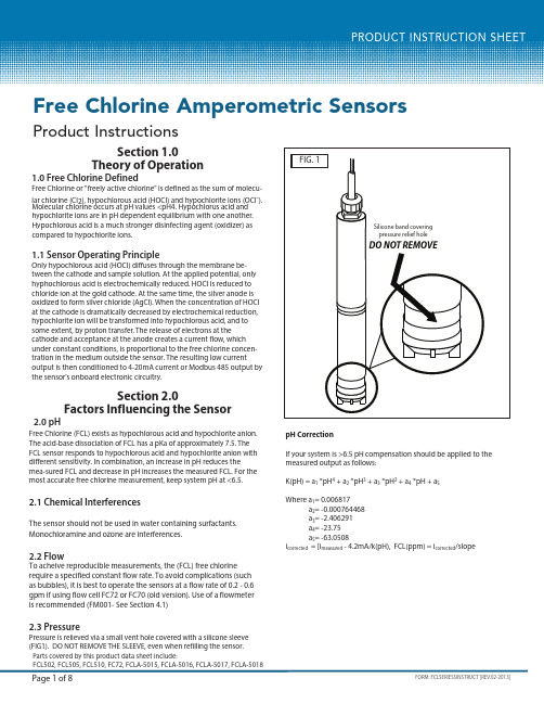
Free Chlorine Amperometric SensorsProduct InstructionsParts covered by this product data sheet include:FCL502, FCL505, FCL510, FC72, FCLA-5015, FCLA-5016, FCLA-5017, FCLA-50182.0 pHFree Chlorine (FCL) exists as hypochlorous acid and hypochlorite anion. The acid-base dissociation of FCL has a pKa of approximately 7.5. The FCL sensor responds to hypochlorous acid and hypochlorite anion with different sensitivity. In combination, an increase in pH reduces themea-sured FCL and decrease in pH increases the measured FCL. For the most accurate free chlorine measurement, keep system pH at <6.5.2.1 Chemical InterferencesThe sensor should not be used in water containing surfactants. Monochloramine and ozone are interferences.2.2 FlowTo acheive reproducible measurements, the (FCL) free chlorine require a specified constant flow rate. To avoid complications (such as bubbles), it is best to operate the sensors at a flow rate of 0.2 - 0.6 gpm if using flow cell FC72 or FC70 (old version). Use of a flowmeter is recommended (FM001- See Section 4.1)2.3 PressurePressure is relieved via a small vent hole covered with a silicone sleeve (FIG1). DO NOT REMOVE THE SLEEVE, even when refilling the sensor.Section 1.0Theory of Operation1.0 Free Chlorine DefinedFree Chlorine or "freely active chlorine" is defined as the sum of molecu-lar chlorine (Cl 2), hypochlorous acid (HOCl) and hypochlorite ions (OCl -). Molecular chlorine occurs at pH values <pH4. Hypochlorus acid and hypochlorite ions are in pH dependent equilibrium with one another. Hypochlorous acid is a much stronger disinfecting agent (oxidizer) as compared to hypochlorite ions.1.1 Sensor Operating PrincipleOnly hypochlorous acid (HOCl) diffuses through the membrane be-tween the cathode and sample solution. At the applied potential, only hyphochlorous acid is electrochemically reduced. HOCl is reduced to chloride ion at the gold cathode. At the same time, the silver anode is oxidized to form silver chloride (AgCl). When the concentration of HOCl at the cathode is dramatically decreased by electrochemical reduction, hypochlorite ion will be transformed into hypochlorous acid, and to some extent, by proton transfer. The release of electrons at the cathode and acceptance at the anode creates a current flow, which under constant conditions, is proportional to the free chlorine concen-tration in the medium outside the sensor. The resulting low currentoutput is then conditioned to 4-20mA current or Modbus 485 output by the sensor's onboard electronic circuitry.Section 2.0Factors Influencing the SensorpH CorrectionIf your system is >6.5 pH compensation should be applied to the measured output as follows:K(pH) = a 1 *pH 4 + a 2 *pH 3 + a 3 *pH 2 + a 4 *pH + a 5Where a 1= 0.006817 a 2= -0.000764468 a 3= -2.406291a 4= -23.75 a 5= -63.0508i corrected = [i measured - 4.2mA/k(pH), FCL(ppm) = i corrected /slopeFC72 Flow cellEnsure flow cell is mounted at 45 deg or higher above horizon-tal as shown in FIG 2B.4.1 Flow MeterTo control flow to the flow cell, a flow meter is recommended.Sensorex supplies model FM001 for this purpose. The FM001provides flow control from 0.1 to 1.0 GPM (0.5 to 4.0 LPM) with94% accuracy.FIG. 3SECTION 5.0Sensor Installation5.0 Sensor Installation into Flow Cella)First install threaded fitting onto sensor body (remove fitting if pre-installed in flow cell) FIG 2d b)Install snap-ring into groove on sensor bodyc)Next, slide o-ring onto body of sensor until it reaches bottom of threaded fitting.d) Thread sensor assembly into top of flow cell as shown in FIG 2c.e) Turn on flow and verify the flow through the Flow Cell is at least 0.2 gpm (45 liters/hour and no more than 0.6gpm (135 liters/hour).6.0 Electrical InstallationThe sensor is supplied in 2 output types, 4-20mA or Modbus 485.Ou tput of 4 mA in air and 20 mA at the top range of free chlorine output (0-2ppm, 0-5ppm and 0-10ppm) or Modbus 485.NOTE: The supply voltage to the Sensor must be 12-24 V DC with minimum of 250 mA. Maximum load is 1 Watt. The sensor has 2 wires, red (+), black (-). Attach the red wire to the power supply positive ter-minal (+) and the black wire to the PLC or DVM positive (+) terminal. Connect a wire (customer supplied) from the power suppy negative (-) and the PLC or DVM (-). See FIG 3. See FIG3A for Modbus connections.SECTION 6.0Electrical InstallationSECTION 7.0Sensor Conditioning7.0 Sensor ConditioningThe sensor requires conditioning prior to generating stable values.a) For new Sensors, connect the sensor to power and allow to run overnight (at least 12 hours) before calibration.b) If the Sensor will be un-powered for two hours or more, run for two hours prior to use.c) If the Sensor's flow will be off for one hour or less, run the sensor for at least one hour prior to recalibration.d) After membrane/electrolyte replacement, allow the Sensor to run powered overnight (at least 12 hours) before calibration .4.1.1 Install the flow meter and flow cell as shown in FIG 2C.Follow the diagram so that the incoming water is attached to the bottom of the flow meter (where flow adjustment knob is located).FIG. 7FIG. 6c) Adjust span/slope at PLC/4-20mA devic e for 4-20mA models only.d) Repeat this slope calibration one day after sensor is initially installed.e) Repeat the slope calibration weekly.Section 9.0Sensor Storage9.0 StorageStore sensor at 5o C - 50o C only and maximum humidity of 95% non-condensing.a) Short Term Storage (one week or less): Store in Flow cell with water to prevent the probe from drying out.b) Intermediate Term (one week to one month): Store with cap on sen-sor in a beaker with water to keep membrane wet.c) Long Term (one month or longer): Remove Membrane Cap and store cap completely immersed in tap water. Remove fill solution and pour down drain.Note: Electrolyte shelf life is one year from date of mfg (see bottle).Section 10.0Sensor Maintenance10.0 Membrane Cap ReplacementIf membrane replacement is required, a new cap with preinstalled mem-brane must be used. Two caps and 2 bottles of refill solution are shipped with each sensor. Additional caps are ordered as FCLA-5016, and refill solution as FCLA-5015.To change membrane cap:a) Turn sensor upside down with cap facing upward.b) Rotate cap counter-clockwise to remove (SEE FIG 5).c) Place needle tip on syringe as shown in FIG 6d) Remove solution from bottle with needle and syringe (FIG 7)e) Fill sensor body with electrolyte using needle and bottle of refill solution until it flows out of the holes near the cathode(SEE FIG 8).f) Add a few drops of electrolyte to the membrane cap (FIG 9)g) Install new membrane cap by threading cap onto sensor rotating cap clockwise (Opposite of FIG 5).DO NOT TOUCH THE CATHODE DURING THIS PROCESS SINCE IT CAN BE DAMAGED.F C LA -7000F C L A -7000FIG. 3A3. Pressure fluctuation in sample lineFCLA-7000Free Chlorine /Chlorine Dioxide Colorimeter-eXact 7+, requires CLDA-7001 strips5.58"(142mm)3.82"(97mm)2.25"(57mm)2.25"(57mm)4.61"(117mm)10.19"(259mm)3.78"(96mm)GPM LPMstay this way – do not put a flat on the cathode.7))Check tbrighter and shinier than before (FIG. 5) the operation using the abrasive paper. 8))as the gold surface can be easily damaged.membrane pocket (FIG. 7)the sensor.cap with a towel.10.0DAMAGE TO THE GOLD ELECTRODE.* *。
- 1、下载文档前请自行甄别文档内容的完整性,平台不提供额外的编辑、内容补充、找答案等附加服务。
- 2、"仅部分预览"的文档,不可在线预览部分如存在完整性等问题,可反馈申请退款(可完整预览的文档不适用该条件!)。
- 3、如文档侵犯您的权益,请联系客服反馈,我们会尽快为您处理(人工客服工作时间:9:00-18:30)。
Towards Bezel
5
Towards ASIC
Diagram of Host Board Connector Block Pin Numbers and Names
Finisar Corporation October 26, 2005 Rev A
Page 2
芯天下--/
Finisar’s FTLF1421P1xCL Small Form Factor Pluggable (SFP) transceivers are compatible with the Small Form Factor Pluggable Multi-Sourcing Agreement (MSA)1. They comply with SONET OC-48 IR-1 (SDH STM S-16.1) standards2, Gigabit Ethernet as specified in IEEE Std 802.33 and Fibre Channel FC-PI 13.04. They are compatible with SONET OC-12 and SONET OC-3 standards2. Digital diagnostics functions are available via the 2-wire serial bus specified in the SFP MSA. They are RoHS compliant and leadfree per Directive 2002/95/EC5 and Finisar Application Note AN-2038. PRODUCT SELECTION
2
3
300
Vcc – 0.5 e 100
4 5 5 6 6 7
Notes: 1. Non condensing 2. AC coupled. 3. Or open circuit. 4. Into 100 ohm differential termination. 5. 20 – 80 % 6. Loss Of Signal is LVTTL. Logic 0 indicates normal operation; logic 1 indicates no signal detected. 7. All transceiver specifications are compliant with a power supply sinusoidal modulation of 20 Hz to 1.5 MHz up to specified value applied through the power supply filtering network shown on page 23 of the Small Form-factor Pluggable (SFP) Transceiver MultiSource Agreement (MSA), September 14, 2000.
VeeT 1 2 3 4 VeeT TDTXFault TD+ TX Disable VeeT MOD-DEF(2) VccT 16 15 14 13 12 11 MOD-DEF(1) VccR 6 7 8 9 10 MOD-DEF(0) VeeR Rate Select RD+ LOS RDVeeR VeeR VeeR 17 18 19 20
FTLF1421P1xCL Pluggable SFP Product Specification – October 2005
Finisar
II.
Absolute Maximum Ratings
Symbol Vcc TS TOP RH Min -0.5 -40 -10 0 Typ Max 4.5 85 70 85 Unit V °C °C % Ref.
Symbol Vcc Icc Rin Vin,pp VD VEN Vout,pp tr tf VLOS fault VLOS norm PSR JRXp-p JRXrms Min 3.00 Typ 200 100 250 Vcc – 1.3 Vee 1200 Vcc Vee+ 0.8 10 400 100 100 800 175 175 VccHOST Vee+0.5 0.07 0.007 Max 3.60 300 Unit V mA Ω mV V V us mV ps ps V V mVpp UI UI Ref.
Finisar
Product Specification
OC-48 IR-1/STM S-16.1 RoHS Compliant Pluggable SFP Transceiver
FTLF1421P1xCL
PRODUCT FEATURES • • • • • • • • • • • Up to 2.67Gb/s bi-directional data links Hot-pluggable SFP footprint Built-in digital diagnostic functions Uncooled DFB 1310nm laser transmitter Duplex LC connector RoHS compliant and lead-free Metal enclosure, for lower EMI FEC Support Single 3.3V power supply Low power dissipation <700mW typical Commercial operating temperature range: -10°C to 70°C APPLICATIONS • • • • SONET OC-48 IR-1 / SDH STM S-16.1 SONET OC-12 SR / SDH STM I-4 SONET OC-3 SR / SDH STM I-1 Gigabit Ethernet / 1x/2x Fibre Channel
Parameter Maximum Supply Voltage Storage Temperature Case Operating Temperature Relative Humidity
1
III.
Electrical Characteristics (TOP = -10 to 70 °C, VCC = 3.00 to 3.60 Volts)
1
1
1
Notes: 1. Circuit ground is internally isolated from chassis ground. 2. Laser output disabled on TDIS >2.0V or open, enabled on TDIS <0.8V. 3. Should be pulled up with 4.7k – 10kohms on host board to a voltage between 2.0V and 3.6V. MOD_DEF(0) pulls line low to indicate module is plugged in. 4. Finisar FTLFxx21xxxxx transceivers operate between OC-3 and OC-48, 1x and 2x Fibre Channel, and Gigabit Ethernet data rates and respective protocols without active control. Finisar FTLFxx19xxxxx transceivers operate at 1x and 2x Fibre Channel, and Gigabit Ethernet data rates and respective protocols without active control. 5. LOS is open collector output. Should be pulled up with 4.7k – 10kohms on host board to a voltage between 2.0V and 3.6V. Logic 0 indicates normal operation; logic 1 indicates loss of signal.
Finisar
I.
Pin 1 2 3 4 5 6 7 8 9 10 11 12 13 14 15 16 17 18 19 20
Pin Descriptions
Symbol VEET TFAULT TDIS MOD_DEF(2) MOD_DEF(1) MOD_DEF(0) Rate Select LOS VEER VEER VEER RDRD+ VEER VCCR VCCT VEET TD+ TDVEET Name/Description Transmitter Ground (Common with Receiver Ground) Transmitter Fault. Not supported. Transmitter Disable. Laser output disabled on high or open. Module Definition 2. Data line for Serial ID. Module Definition 1. Clock line for Serial ID. Module Definition 0. Grounded within the module. No connection required Loss of Signal indication. Logic 0 indicates normal operation. Receiver Ground (Common with Transmitter Ground) Receiver Ground (Common with Transmitter Ground) Receiver Ground (Common with Transmitter Ground) Receiver Inverted DATA out. AC Coupled. Receiver Non-inverted DATA out. AC Coupled. Receiver Ground (Common with Transmitter Ground) Receiver Power Supply Transmitter Power Supply Transmitter Ground (Common with Receiver Ground) Transmitter Non-Inverted DATA in. AC Coupled. Transmitter Inverted DATA in. AC Coupled. Transmitter Ground (Common with Receiver Ground) Ref. 1 2 3 3 3 4 5 1 1 1