SF10A600H中文资料
汇川技术 MD600系列 简易型变频器 硬件手册 A00

‑1‑前言资料简介本产品是一款简易型通用变频器,具备小体积、高耐环境能力、简单易用、可靠、增效、节能等特点,主要用于控制和调节三相交流异步机转速,可用于硅晶、锂电、木工、物流、食品饮料、线缆、机床、简易风机泵类负载的驱动。
本手册介绍产品的选型、机械设计、电气设计,以及产品符合认证及标准等详细内容。
更多资料版本变更记录关于手册获取本手册不随产品发货,如需获取电子版PDF文件,可以通过以下方式获取:●登录汇川技术官方网站( ),“服务与支持‑资料下载”,搜索关键字并下载。
●使用手机扫产品机身二维码,获取产品配套手册。
保修声明正常使用情况下,产品发生故障或损坏,汇川技术提供保修期内的保修服务(产品保修期请详见订货单)。
超过保修期,将收取维修费用。
保修期内,以下情况造成的产品损坏,将收取维修费用。
●不按手册中的规定操作本产品,造成的产品损坏。
●火灾、水灾、电压异常,造成的产品损坏。
●将本产品用于非正常功能,造成的产品损坏。
●超出产品规定的使用范围,造成的产品损坏。
●不可抗力(自然灾害、地震、雷击)因素引起的产品二次损坏。
前言前言有关服务费用按照厂家统一标准计算,如有契约,以契约优先的原则处理。
详细保修说明请参见《产品保修卡》。
‑2‑目录目录前言 (1)安全注意事项 (5)1产品概述 (9)2产品信息 (10)2.1型号与铭牌说明 (10)2.2部件说明 (11)3产品型号表 (13)4选型流程 (14)5选型一览表 (15)6产品规格 (16)6.1电气规格 (16)6.2技术规格 (18)7选配件 (20)7.1选配件一览表 (20)7.2操作面板 (20)7.3线缆 (21)7.3.1主回路线缆 (21)7.3.2控制回路线缆 (23)7.3.3线耳选型 (24)7.4外围电气元件 (24)7.4.1断路器、保险丝、电磁接触器 (24)7.4.2交流输入电抗器 (25)7.4.3输出电抗器 (27)7.4.4EMC滤波器 (31)7.4.5磁环与磁扣 (34)7.4.6制动电阻 (36)8机械设计 (39)8.1柜体设计 (39)8.1.1安装空间要求 (39)8.1.2结构尺寸 (43)8.1.2.1产品尺寸 (43)8.2EMC设计 (44)8.2.1电磁兼容性说明 (44)8.2.1.1概述 (44)8.2.1.2电磁兼容的分类 (44)8.2.1.3干扰辐射、抗干扰性 (44)8.3散热设计 (44)8.3.1散热方案 (44)‑3‑目录8.3.2通风要求 (45)8.3.2.1风道设计 (45)8.3.2.2进出风口 (45)8.3.3风扇设计 (49)9电气设计 (51)9.1电气设计指导 (51)9.1.1外围元件设计 (51)9.1.1.1选择保险丝、断路器、电磁接触器 (51)9.1.1.2选择EMC滤波器 (51)9.1.1.3选择交流输入电抗器 (52)9.1.1.4选择输出电抗器 (52)9.1.1.5选择SPD (52)9.1.1.6选择磁环与磁扣 (53)9.1.1.7选择制动电阻 (54)9.1.2选择电机 (54)9.1.3检查电机和驱动器的兼容性 (55)9.1.4选择动力线缆 (55)9.1.4.1需要遵循的规则 (55)9.1.4.2动力线缆类型 (55)9.1.4.3动力线缆规格 (56)9.1.5选择控制线缆 (56)9.1.5.1需要遵循的规则 (56)9.1.5.2控制线缆类型 (56)9.1.5.3控制线缆规格 (56)9.1.6选择通信线缆 (57)9.1.6.1CAN通信线缆 (57)9.1.6.2Modbus通信线缆 (57)9.1.7线缆布线 (58)9.1.7.1规范说明 (58)9.1.7.2布线建议 (59)9.2系统连接图 (63)9.2.1系统连接示意图 (63)9.2.2系统构成说明 (65)9.3电气接线图 (66)9.4接线端子分布 (68)9.4.1主回路端子介绍 (68)9.4.2控制回路端子介绍 (69)10符合认证及标准要求 (74)10.1符合认证、指令及标准 (74)10.2CE认证 (74)10.2.1对应欧洲标准时的注意事项 (74)10.2.2符合EMC指令的条件 (74)10.2.3符合LVD低电压指令的条件 (75)11服务与支持 (77)‑4‑安全注意事项安全注意事项安全声明●本章对正确使用本产品所需关注的安全注意事项进行说明。
XH600型门式金属探测器说明书
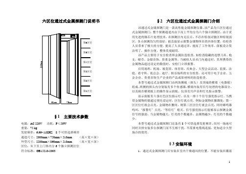
六区位通过式金属探测门说明书§1 主要技术参数电源:AC 220V 功耗:P≤50W重量:75 kg发射频率:6.99~11KHZ 8个可供选择频率通道尺寸:2000mm×750mm×510mm (高×宽×深)外型尺寸:2200mm×860mm×510mm (高×宽×深)区位:从下至上门体内分6个独立探测区位符合标准:GB15210-2003§2 六区位通过式金属探测门介绍该通过式金属探测门是一款高性能金属探测仪器。
该产品为六区位通过式金属探测门,整个探测通道内由下而上平均分为六个独立探测区,由于采用先进的微芯片处理技术,在探测区内无盲点,不存在特别灵敏区和特别弱区,各点探测均匀性很好,能直接显示报警金属物所在的具体位置,给检查人员带来了极大的方便,提高了人员通过率,提高了工作效率。
面板设计简洁明了,操作方便,整体美观耐用。
该产品主要用于安全检查和金属防盗检查,如检查隐藏的违禁刀具、枪支,硬币、金银首饰、贵重金属等。
当被检人员从门内通过时,其所携带的金属物品超过设定的数值时,安检门立即报警。
应用场所:机场、展览馆、体育馆、庆典会、大型会议活动、监狱、法庭、看守所、夜总会、迪厅、娱乐场所的安全检查,还可用于电子企业、五金企业、贵重首饰生产企业的产品或原材料的防盗检查。
本型号通过式金属探测门由两块侧板(探头)及顶端的横梁(电器箱)组成。
两侧的探头内分别装有多个传感器,横梁内装有信号处理的电器部分,以及嵌在横梁板上的操作显示面板。
仪器使用声音和灯光指示报警。
显示面板有六条红色区位指示灯,以及一排十个信号强度指示灯。
当携带金属物的量超过预先设定时,区位灯就点亮。
例如金属物在脚踝处,第一区区位灯就会点亮,金属物在腰间,则第三区区位灯就会点亮,同时蜂鸣器鸣叫,‘报警灯’点亮,‘等待灯’熄灭。
信号强度指示灯能够显示探测金属信号的强弱。
600h钢规格

600h钢规格
600h钢规格是指一种特定的钢材规格,下面将介绍其具体的特点和应用领域。
600h钢规格是一种高强度合金钢,其主要成分为铁、碳、铬、镍、钼等元素。
它具有优良的耐腐蚀性、耐高温性和高强度特点,因此被广泛应用于航空航天、汽车制造、石化等领域。
600h钢规格在航空航天领域有着重要的应用。
由于航空航天领域对材料性能的要求非常高,600h钢规格的高强度和耐高温性使其成为制造航空发动机零部件、导弹外壳、航天器结构等关键部件的理想选择。
600h钢规格的优异性能能够保证航空航天器在极端条件下的安全运行。
600h钢规格在汽车制造行业也有重要应用。
随着汽车工业的发展,对汽车零部件的要求也越来越高。
600h钢规格具有良好的强度和抗腐蚀性能,能够有效延长汽车零部件的使用寿命,并提高汽车的安全性能。
因此,600h钢规格常被用于汽车发动机缸体、底盘及悬挂系统等关键部件的制造。
600h钢规格在石化行业也有广泛的应用。
石化工艺中的高温高压环境对材料的要求非常严苛,而600h钢规格具有出色的耐腐蚀性和耐高温性能,能够在恶劣的工况下保持稳定的性能。
因此,600h钢规格常被用于石油化工设备、炼油装置、化工容器等领域,确保工
艺设备的安全运行。
600h钢规格作为一种高强度合金钢,具有优良的耐腐蚀性、耐高温性和高强度特点,被广泛应用于航空航天、汽车制造、石化等领域。
它的应用能够提高产品的性能和可靠性,为相关行业的发展做出了重要贡献。
随着科技的不断发展,相信600h钢规格在更多领域将有更广泛的应用。
森沃HSF600系列变频器 使用说明书

HSF600系列高性能变频器使用说明书成都森沃电气有限责任公司序言感谢您选用成都森沃电气有限责任公司生产的HSF600系列高性能变频器!在安装、操作、维护、检查变频器之前,请认真阅读本使用说明书,充分发挥变频器功能,确保使用者安全。
本使用说明书简要介绍了HSF600系列变频器的性能、安装接线、参数设定及操作使用的有关事项。
在使用(安装、运行、维护、检查等)前,请务必认真阅读。
另外,请在理解产品的安全注意事项后再使用该产品。
本使用说明书的示图,是为了方便说明,可能与产品会略有不同,由于产品升级,也有可能略有不同,请以实物为准。
请注意将本使用说明书交到最终用户手中,并妥善保存,以使日后检修、维护时使用。
随着产品的不断改善,本手册如有变更,恕不另行通知。
如有疑问,请及时与本公司或本公司代理商取得联系,我们将竭诚为您服务。
目录1.开箱检查注意事项 (1)2.安全注意事项 (2)2.1 安全标识 (2)2.2 安全事项 (2)3.产品信息 (5)3.1 型号说明 (5)3.2 系列规格 (5)3.3基本性能及配置 (7)3.4结构及外形安装尺寸 (9)3.5保养与维护 (13)3.6保修 (15)3.7报废 (15)4.安装与接线 (16)4.1机械安装 (16)4.2电气接线 (18)5.基本操作与运行 (26)5.1操作面板外观 (26)5.2面板的基本操作 (27)5.3通电 (30)5.4运行 (31)6.功能参数 (38)6.1 参数简表 (38)6.2基本参数组 (65)6.3电机及其保护参数组 (71)I6.4电机控制参数组 (73)6.5输入输出端子参数组 (78)6.6故障保护参数组 (99)6.7电机启停参数组 (107)6.8键盘面板参数组 (114)6.9附加功能参数组 (118)6.10通信功能参数组 (123)6.11过程PID参数组 (127)6.12监视功能参数组 (131)7.故障诊断与对策 (134)7.1 故障代码、原因与对策 (134)7.2 提示和报警代码说明 (137)7.3 故障发生后变频器的再起动 (138)附录A:串行通信 (139)A1.RS485总线 (139)A2.Modbus协议 (140)附录B:制动单元/电阻选型 (150)II1.开箱检查注意事项在开箱时,请仔细确认:(1)箱内含有您订购的机器、产品合格证、产品说明书及保修单;(2)机器侧面铭牌上的产品型号是否与您的订购要求一致;(3)产品在运输过程中是否有破损现象;(4)若发现有某种遗漏、损坏或其他问题,请速与本公司或代理商联系解决。
SF600 操作说明书
THERMAL PRINTER
操作说明书 R e v. B
SF600ʢ 600dpiʣ
S F 6 0 0 - C u t t e r ʢ 切割器ʣ
S F 6 0 0 - P e e l e r ʢ 剥离器ʣ
墨带的安装 ŋŋŋŋŋŋŋŋŋŋŋŋŋŋŋŋŋŋŋŋŋŋŋŋŋŋŋŋŋŋŋŋŋŋŋŋŋŋŋŋŋŋŋŋŋŋŋŋŋŋŋŋŋŋŋŋŋŋŋŋŋŋŋŋŋŋŋŋŋŋŋŋŋŋŋŋŋŋŋŋŋŋŋŋŋŋŋŋ
打印纸的安装 ŋŋŋŋŋŋŋŋŋŋŋŋŋŋŋŋŋŋŋŋŋŋŋŋŋŋŋŋŋŋŋŋŋŋŋŋŋŋŋŋŋŋŋŋŋŋŋŋŋŋŋŋŋŋŋŋŋŋŋŋŋŋŋŋŋŋŋŋŋŋŋŋŋŋŋŋŋŋŋŋŋŋŋŋŋŋ
■ 前言
首先,衷心感谢您购买本产品! 本操作说明书主要记述了正确使用本产品的操作方法以及在使用上的注意事项。所以在使用之前,请完整仔 细地阅读本操作说明书,并在此基础上加以正确使用。另外,请注意妥善保管好本操作说明书,以便可以在 需要时能够随时使用。
日东电工株式会社 为了安全正确地使用本打印机,在操作之前请务必仔细阅读“安全注意事项”。
打开包装及设置ŋŋŋŋŋŋŋŋŋŋŋŋŋŋŋŋŋŋŋŋŋŋŋŋŋŋŋŋŋŋŋŋŋŋŋŋŋŋŋŋŋŋŋŋŋŋŋŋŋŋŋŋŋŋŋŋŋŋŋŋŋŋŋŋŋŋŋŋŋŋŋŋŋŋŋŋŋŋŋŋŋŋŋŋ
打开包装 ŋŋŋŋŋŋŋŋŋŋŋŋŋŋŋŋŋŋŋŋŋŋŋŋŋŋŋŋŋŋŋŋŋŋŋŋŋŋŋŋŋŋŋŋŋŋŋŋŋŋŋŋŋŋŋŋŋŋŋŋŋŋŋŋŋŋŋŋŋŋŋŋŋŋŋŋŋŋŋŋŋŋŋŋŋŋŋ 附属品的确认ŋŋŋŋŋŋŋŋŋŋŋŋŋŋŋŋŋŋŋŋŋŋŋŋŋŋŋŋŋŋŋŋŋŋŋŋŋŋŋŋŋŋŋŋŋŋŋŋŋŋŋŋŋŋŋŋŋŋŋŋŋŋŋŋŋŋŋŋŋŋŋŋŋŋŋŋŋŋŋŋŋŋŋ 保护器具的拆除 ŋŋŋŋŋŋŋŋŋŋŋŋŋŋŋŋŋŋŋŋŋŋŋŋŋŋŋŋŋŋŋŋŋŋŋŋŋŋŋŋŋŋŋŋŋŋŋŋŋŋŋŋŋŋŋŋŋŋŋŋŋŋŋŋŋŋŋŋŋŋŋŋŋŋŋŋŋŋŋŋ 设置环境 ŋŋŋŋŋŋŋŋŋŋŋŋŋŋŋŋŋŋŋŋŋŋŋŋŋŋŋŋŋŋŋŋŋŋŋŋŋŋŋŋŋŋŋŋŋŋŋŋŋŋŋŋŋŋŋŋŋŋŋŋŋŋŋŋŋŋŋŋŋŋŋŋŋŋŋŋŋŋŋŋŋŋŋŋŋŋŋ 电源插头的连接 ŋŋŋŋŋŋŋŋŋŋŋŋŋŋŋŋŋŋŋŋŋŋŋŋŋŋŋŋŋŋŋŋŋŋŋŋŋŋŋŋŋŋŋŋŋŋŋŋŋŋŋŋŋŋŋŋŋŋŋŋŋŋŋŋŋŋŋŋŋŋŋŋŋŋŋŋŋŋŋŋ 与计算机的连接 ŋŋŋŋŋŋŋŋŋŋŋŋŋŋŋŋŋŋŋŋŋŋŋŋŋŋŋŋŋŋŋŋŋŋŋŋŋŋŋŋŋŋŋŋŋŋŋŋŋŋŋŋŋŋŋŋŋŋŋŋŋŋŋŋŋŋŋŋŋŋŋŋŋŋŋŋŋŋŋŋ
SilverStone Strider Plus ST60F-PS 600W 单相电源说明书

SPECIFICATIONSilverStone Strider PlusST60F-PSATX12V / EPS 12V Switching Power SupplyWith Active PFC 80Plus SilverPS/2011.1 ScopeThis specification defines the performance characteristics of a single phase 600watts, 5 output power supply. This specification also defines worldwide safety andelectromagnetic compatibility requirements for the power supply which is intended for use in computer products.1.General2.1 Input VoltageNominal Voltage Voltage Variation Range 100-240 Vrms 90 - 264 Vrms 2.Input Characteristics2.2 Input FrequencyNominal Frequency Frequency Variation Range 50-60 Hz 47 Hz to 63 Hz* The power supply must operate at above frequency with 90-264 VACrms input voltage range.022.3 Max. Input AC CurrentMax. Input Current Measuring Range 8A 90 - 264 Vrms2.4 Inrush CurrentThe power supply must meet inrush requirements for any rated AC voltage, during turn on at any phase of AC voltage, during a single cycle AC dropout condition, during repetitive ON/OFF cycling of AC, and over the specified temperature range.The peak inrush current shall be less than the ratings of its critical components (including input fuse, bulk rectifiers, and surge limiting device).2.5 EfficiencySST-ST60F-PS provides an efficiency of 85% minimum when measured at full load under 115V/60Hz condition.3.1 Normal Operation Output3.Output characteristicsMaximum continuous total DC output power should not exceed 600W.Maximum continuous combined load on +3.3VDC and +5VDC outputs shall not exceed 130W.Maximum combined load on +12V outputs shall not exceed 588W.NOTE:Noise test should be measured with 20 MHz bandwidth frequency oscilloscope. The output terminal shall add a tantalum capacitor of 10uF in parallel with a ceramic capacitor of 0.1uF.033.2 Remote On/Off Controlled modeThe PSON# signal is required to remotely turn on/off the power supply,PSON# is an active low signal that turns on the output power rails. When this is not pulled low by the system, or left open, the outputs (except the +5VSB) turn off. This signal is pulled to a standby voltage by a pull-up resistor internal to the power supply.TTL level "H" 2.0 V - 5.25 V "L" 0.0 V – 1.0 V3.3 RegulationThe cross regulation defined as follows, the output regulation should be within the specified range.3.4 Rise TimeDC output rise time is less than 20 mS at nominal line and full load.3.5 Hold-up TimeDC +5V output maintains at least 12mS after power off which hold within para 3.1 under 230V/50Hz condition.3.6 5VSB5VSB is requierd for the implementation of PS-ON described above. 5VSB is a standby voltage that may be used to power circuits that require power input during the powered-down state of all power rails. The 5 VSB pin should deliver 5V ± 5% at a minimum of 3.0 A for PC board circuits to operate. Conversely,PC board should draw no more than 3.0A maximum form this pin. This power may be used to operate circuits such as soft power control.043.7 PG-OKPG-OK is a power good signal and should be asserted high by power supply to indicate that the +5 VDC and +3.3 VDC outputs are above the under-voltage thresholds of the power supply. When this signal is asserted high, there should be sufficient mains energy stored by the converter to guarantee continuous power operation within specification. Conversely, when either the +5VDC or the +3.3VDC output voltage falls below the under-voltage threshold, or when mains power has been removed for a time sufficiently long so that power supplyoperation is no longer guaranteed, PG-OK should be deasserted to a low state.See Figure 1 for a representation of the timing characteristics of the PG-OK,PS-ON, and germane power rail signals.3.8 3.3V SenseA default 3.3V sense line should be implemented pin 13 of the connector.3.9 Capacitive LoadThe power supply should be able to power up and operate normally with the following capacitances simultaneously present on the DC outputs.4.1 Input ProtectionIn primary circuit of the power supply , a protected fuse is inserted. Only internal fault of the power supply will cause the fuse blown. Any overload or short circuit at DC output will keep from fuse brown or fire hazard.4.Protection054.2 Output Protection4.2.1 Under voltage protection 4.2.1 Under voltage protectionThe +5V/+12V/+3.3V DC output are protected against the under voltage condition . range value can't be exceed 3.3~3.7V at 5V terminal and 8.5~9.5V at 12V, 2.0~2.4V at 3.3V.4.2.2 Over Voltage ProtectionThe +12V/ DC output are protected against the over voltage condition . Maximum value can't be over 15.5V at 12V.4.2.3 Over Power ProtectionThe power supply can be used electronic circuit to limit the output current against exceeding 60% of surge output power or protected against excessive power delivery since short circuit of any output or over total power at high line.4.2.4 Short Circuit ProtectionShort circuit placed on +5V,+12V,+3.3V,-12V will latch off. +5VSB will auto-recovery.4.2.5 Over-Current ProtectionCurrent protection should be designed to limit the current to operate within safe operating conditions. Over current protection schemes where only the voltage output that experiences the over current event is shut off may be adequate to maintain safe operation of the power supply and the system; however, damage to the motherboard or other system components may occur. The recommended over current protection scheme is for the power supply to latch into the shutdown state. The setting of over current protection for each output rail is as following.4.2.6 Over-Temperature ProtectionThis power supply includes an over-temperature protection sensor, which can trip and shut down the power supply at 110℃065.1 No Load StartWhen power is applied to SST-ST60F-PS with no load connected or under minimum load connected, neither damage to power supply nor hazards to users will occur.5.2 Cold StartThe power supply shall operate properly when first applied at normal input voltage and or so maximum load after 4 hours storage in 0℃ environment.5.Start Stability6.1 Temperature and Humidity6.2 AltitudeThe power supply can operate normally at any altitude between 0 to 10000 feet.6.3 Vibration and ShockSweep and resonance search for each of X,Y,Z, axis at the sweep.RATE of 1/OCTAVE/Min.6.Environments7. Conducted EMI6.1.1 Operating Temperature 0 to 40 ℃ Relative Humidity 20 to 90 %6.1.2 StorageTemperature -40 to 70 ℃Relative Humidity 20 to 95 % noncondensing078.1 Safety Requirement8.2 Leakage CurrentThe AC leakage current is less than 3.5mA when the power supply connect to 264Vac/50Hz .8.3 Insulation ResistanceThe insulation resistance should be not less than 30M ohm after applying of 500VDC for 1 minute.8.4 Dielectric Voltage WithstandThe power supply shall withstand for 1 minute without breakdown the application of a V AC voltage applied between both input line and chassis(20mA DC cut-off current). Main transformer shall similarly withstand 3000Vacapplied between both primary and secondary windings for a minimum of one minute.8. Product SafetyA TTL compatible signal for the purpose of initiating an orderly start-up procedure under normal input operating conditions. During power up, this signal is asserted ( low ) until +5V is under regulation and AC reaches min. line specification range. After all voltage are going appropriate level, the system may have a turn on delay of 100mS, but no greater than 500mS. During power off the signal should go to low level before +5V is out of regulation. The low level is 0 to 0.8V and high level is 4.75 to 5.25V. The " Power Good "signal can drive up to 6 standard TTL loads.9. Power Good Signal08* T1 : Turn on time ( 2 sec. Max.) * T2 : Rise time ( ≦ 20mS Max.)* T3 : Power good turn on delay time ( 100 < T3 < 500 mS )* T4 : Switch on time (0.5 sec. Max.)* T5 : Power good turn off delay time ( 1.0 mS Min.) PS-ON/OFF * T6 : Power hold-on time ( 12 mS Min.)* Power on-off cycle :When the power supply is turned off for a minimum of 2.0 sec. and turn on again, the power good signal will be asserted.The MTBF of the power should be 100,000 hours min.10. MTBF11.1 Input VoltageApplying 220Vac for 230V model.11.2 Test ConditionApplying 75% loads for the power supply in 45 (+/-5) oC chamber for 4 hours.11. Burn-InTime Diagram Figure 1AC+5Vs PS-ON/OFF+5V O/PPower Good0914.1 Physical Dimension150 mm (W) × 86 mm (H) × 140mm (D)14.2 Connectors14. Mechanical RequirementsM/B 24PIN connectorThe product shall meet requirement for EN61000-3-2 & EN61000-3-3 :1995 standard of class D, test at 230Vac 50Hz.12. HarmonicsThe power supply with active power factor correction, and meet the EN61000-3-2 standards, The power factor is greater than 0.9 at 230V/50Hz, Max. load.13.Power Factor104PIN peripheral connector (HDD) 4PIN floppy connector (FDD)ATX 12V 4PIN (4+4PIN EPS 12V in split mode)EPS 12V 8PIN connectorSATA connector116PIN PCI Express connector8PIN PCI Express connector12Warranty InformationThis product has a limited 3 year warranty in North America, Europe, and Australia.For information on warranty periods in other regions, please contact your reseller or SilverStone authorized distributor.Additional info & contactsFor North America (*****************************)SilverStone T echnology in North America may repair or replace defective product with refurbished product that is not new but has been functionally tested. Replacement product will be warranted for remainder of the warranty period or thirty days, whichever is longer. All power supplies should be sent back to the place of purchase if it is within 30 days of purchase, after 30 days, customers need to initiate RMA procedure with SilverStone T echnology in USA by first downloading the “USA RMA form for end-users” form from the below link and follow its instructions./contactus.phpFor Australia only (**************************)Our goods come with guarantees that cannot be excluded under the Australian Consumer Law.You are entitled to a replacement or refund for a major failure and for compensation for any other reasonably foreseeable loss or damage.Y ou are also entitled to have the goods repaired or replaced if the goods fail to be of acceptable quality and the failure does not amount to a major failure. Please refer to above “Warranty terms & conditions” for further warranty details.SilverStone T echnology Co., Ltd. 12F No. 168 Jiankang Rd., Zhonghe Dist., New T aipei City 235 T aiwan R.O.C. + 886-2-8228-1238 (standard international call charges apply)ForEurope(****************************)Forallotherregions(**************************)。
汇川技术 MD600系列 简易型变频器 功能手册 A00

前言资料简介本产品是一款简易型通用变频器,具备小体积、高耐环境能力、简单易用、可靠、增效、节能等特点,主要用于控制和调节三相交流异步机转速,可用于硅晶、锂电、木工、物流、食品饮料、线缆、机床、简易风机泵类负载的驱动。
本手册介绍产品的功能应用、故障码、功能码等详细内容。
更多资料版本变更记录关于手册获取本手册不随产品发货,如需获取电子版PDF文件,可以通过以下方式获取:●登录汇川技术官方网站( ),“服务与支持-资料下载”,搜索关键字并下载。
●使用手机扫产品机身二维码,获取产品配套手册。
保修声明正常使用情况下,产品发生故障或损坏,汇川技术提供保修期内的保修服务(产品保修期请详见订货单)。
超过保修期,将收取维修费用。
保修期内,以下情况造成的产品损坏,将收取维修费用。
●不按手册中的规定操作本产品,造成的产品损坏。
●火灾、水灾、电压异常,造成的产品损坏。
●将本产品用于非正常功能,造成的产品损坏。
●超出产品规定的使用范围,造成的产品损坏。
●不可抗力(自然灾害、地震、雷击)因素引起的产品二次损坏。
有关服务费用按照厂家统一标准计算,如有契约,以契约优先的原则处理。
详细保修说明请参见《产品保修卡》。
前言目录目录前言 (1)安全注意事项 (7)1功能一览表 (11)2驱动配置 (15)2.1指令通道及命令生效 (15)2.1.1指令通道选择 (15)2.1.2命令生效 (16)2.2设定运行指令 (18)2.2.1控制通道 (18)2.2.2设置运行指令 (19)2.2.3运行指令设定方法 (19)2.2.4通过后台软件设定运行指令 (20)2.2.5通过操作面板设定运行指令 (23)2.2.6通过端子设定运行指令 (23)2.2.7通过通信设定运行指令 (32)2.2.8通过自定义通道设定运行命令 (34)2.3设定频率指令 (36)2.3.1设定通道 (36)2.3.2频率指令输入方法 (37)2.3.3选择主频率指令的输入方法 (37)2.3.4通过操作面板设定主频率 (39)2.3.5通过模拟量(AI)设定主频率 (40)2.3.6通过多段指令设定主频率 (43)2.3.7通过简易PLC设定主频率 (45)2.3.8通过PID设定主频率 (46)2.3.9通过通信设定主频率 (48)2.3.10通过脉冲设定主频率 (50)2.3.11选择辅助频率指令的输入方法 (50)2.3.12选择主、辅频率叠加指令的输入方法 (52)2.3.13设定频率和附加频率 (53)2.3.14设定频率指令极限 (54)2.3.15设定低于最小频率动作 (55)2.4设置启停方式 (56)2.4.1启动方式 (56)2.4.2停止方式 (59)2.4.3加减速时间 (61)3电机调谐 (64)3.1异步机电机调谐 (67)4控制接口 (69)4.1数字输入端子功能(DI) (69)4.2数字输出端子功能(DO) (74)4.3虚拟数字量输入端子(VDI) (77)4.4虚拟数字量输出端子(VDO) (79)4.5高速数字量输入(HDI) (80)4.6模拟量输入端子(AI) (82)目录4.7模拟量输出端子(AO) (85)5控制性能 (89)5.1Vf曲线的设定 (89)5.2输出电流(转矩)限制 (92)5.3过压失速抑制 (92)5.4欠压失速抑制 (94)5.5提高弱磁区性能 (95)5.6辅助控制 (95)5.7制动控制 (97)6功能应用 (98)6.1点动运行 (98)6.2频率检测 (100)6.2.1多段速指令 (100)6.2.2频率检测(FDT) (101)6.2.3跳频 (102)6.2.4反向频率禁止 (104)6.2.5频率到达检出幅度 (104)6.2.6加减速时间切换频率点 (105)6.2.7任意到达频率检测值 (106)6.3电流检测 (107)6.3.1零电流检测 (107)6.3.2输出电流超限 (107)6.3.3任意到达电流 (108)6.4正反转死区时间 (109)6.5定时功能 (109)6.6累计时间到达功能 (110)6.7本次运行到达时间 (111)6.8AI1电压保护上下限 (111)6.9模块温度 (112)6.10散热风扇控制 (112)6.11输出功率校正 (113)6.12用户定制参数 (114)6.13休眠与唤醒 (115)6.14摆频控制功能 (116)6.15定长控制功能 (118)6.16计数功能 (120)6.17多段值 (122)6.18简易PLC功能 (123)6.19通用PID (125)6.20负载监控 (134)6.21应用功能块 (137)6.21.1逻辑运算 (137)6.21.2算数运算 (140)6.22AI自动调整曲线 (143)目录7故障与保护功能 (145)7.1启动保护 (145)7.2缺相保护 (145)7.3电压保护设定 (145)7.4过流保护设定 (148)7.5变频器过载及预过载 (149)7.6变频器过温及预过温 (149)7.7电机过载及预过载 (150)7.8过速保护 (151)7.9速度偏差过大保护 (152)7.10故障自动复位 (152)7.11故障自动重启 (153)7.12故障动作保护选择 (154)7.13自检 (156)8监视功能 (159)9故障处理 (170)9.1故障等级分类及显示 (170)9.1.1故障等级分类 (170)9.1.2故障显示 (170)9.2故障排除流程 (171)9.3故障排除后复位方法 (171)9.4故障现象的排除 (172)9.4.1常见故障现象的排除 (172)9.4.2VF控制模式下试运行的故障排除 (173)9.5故障码一览表 (174)10功能参数分类 (181)11参数说明 (184)11.1F0基本参数设定 (184)11.2F1电机基本参数 (214)11.3F2电机控制参数 (219)11.4A0参数管理 (224)11.5A1当前异常 (233)11.6A2系统信息 (242)11.7A3机型配置 (246)11.8A4硬件配置 (255)11.9A5载频与发波配置 (257)11.10A6操作面板 (260)11.11A8触发示波器 (267)11.12Ab调试功能 (271)11.13AC调度配置 (284)11.14Ad累计功能 (287)11.15AE用户定制参数 (292)目录11.16b0指令通道配置 (299)11.17b1控制通道1主命令字 (300)11.18b2控制通道1辅助命令字 (304)11.19b3控制通道2主命令字 (307)11.20b4控制通道2辅助命令字 (311)11.21b5设定通道1 (314)11.22b6设定通道2 (321)11.23b7斜坡(加减速)设置 (329)11.24b8多段值 (339)11.25b9端子启停模块 (345)11.26C2辨识与自检 (353)11.27C4电机基本参数 (358)11.28C5电机扩展参数 (362)11.29d0电机基本控制 (363)11.30d1电机限制和保护 (371)11.31d2电机-VF控制 (381)11.32d3电机速度控制 (390)11.33d7电机控制优化 (390)11.34E0DI (391)11.35E1DO/RO (413)11.36E2AI (456)11.37E3AO (466)11.38E4HDI (470)11.39E6端子辅助功能 (475)11.40EE输入输出校正(用户) (482)11.41EF输入输出校正(厂家) (484)11.42H1故障等级设置 (486)11.43H2自定义故障 (515)11.44H3故障自动复位/重启 (519)11.45H6历史故障记录1 (525)11.46H7历史故障记录2 (540)11.47H8历史故障记录3 (552)11.48H9历史故障记录4 (564)11.49HA历史故障记录5 (576)11.50Hb历史故障记录6 (588)11.51n0通讯通用配置 (600)11.52n1调测通讯 (603)11.53n2Modbus通讯 (603)11.54n3CAN通讯 (605)11.55nE过程数据地址映射 (607)11.56o0通讯适配 (620)目录11.57o6逻辑运算1 (645)11.58o7逻辑运算2 (669)11.59o8算数运算1 (677)11.60o9算数运算2 (695)11.61P0辅助功能 (706)11.62P1简易PLC (725)11.63P2过程PID (735)11.64L0位连接器1 (744)11.65L1位连接器2 (753)11.66L3位连接器4 (766)11.67L4位连接器5 (773)11.68L5字连接器1 (782)11.69L6字连接器2 (811)11.70L7字连接器3 (820)11.71L9双字链接器1 (823)11.72Lb浮点连接器1 (827)11.73LC浮点连接器2 (838)11.74Ld浮点连接器3 (851)11.75U0常用监视参数0 (859)11.76U2常用监视参数2 (872)11.77U3常用监视参数3 (883)12参数一览表 (888)安全注意事项安全注意事项安全声明●本章对正确使用本产品所需关注的安全注意事项进行说明。
309605ZAB ZH 说明书 — 零配件 VISCON HP 高压流体加热器

309605ZABZH说明书 — 零配件VISCON ® HP高压流体加热器用于各种流体加热。
仅适合专业用途。
最大工作压力为 7250 磅/平方英寸(50 兆帕,500 巴)有关的型号资料,包括最大工作压力和核准使用情况,请参见第 2 页。
重要安全说明书请阅读本手册的所有警告及说明。
请妥善保存这些说明。
WL D危险场所加热器非危险场所加热器目录型号 . . . . . . . . . . . . . . . . . . . . . . . . . . . . . . . . . . . . . .3危险场所加热器 . . . . . . . . . . . . . . . . . . . . . . . . . .3非危险场所加热器 . . . . . . . . . . . . . . . . . . . . . . . .3警告 . . . . . . . . . . . . . . . . . . . . . . . . . . . . . . . . . . . . . .4安装 . . . . . . . . . . . . . . . . . . . . . . . . . . . . . . . . . . . . . .7典型安装 . . . . . . . . . . . . . . . . . . . . . . . . . . . . . . .7组件识别 . . . . . . . . . . . . . . . . . . . . . . . . . . . . . . . . . .8基本信息 . . . . . . . . . . . . . . . . . . . . . . . . . . . . . . .9选择管路 . . . . . . . . . . . . . . . . . . . . . . . . . . . . . . .9安装加热器 . . . . . . . . . . . . . . . . . . . . . . . . . . . .10流体连接及附件 . . . . . . . . . . . . . . . . . . . . . . . . .12电气连接 . . . . . . . . . . . . . . . . . . . . . . . . . . . . . .13接地 . . . . . . . . . . . . . . . . . . . . . . . . . . . . . . . . . .13危险区域布线和导管要求 . . . . . . . . . . . . . . . . .13操作 . . . . . . . . . . . . . . . . . . . . . . . . . . . . . . . . . . . . .15泄压步骤 . . . . . . . . . . . . . . . . . . . . . . . . . . . . . .15首次冲洗 . . . . . . . . . . . . . . . . . . . . . . . . . . . . . .15为系统填料 . . . . . . . . . . . . . . . . . . . . . . . . . . . .15设置加热器控制 . . . . . . . . . . . . . . . . . . . . . . . . .16喷涂调节 . . . . . . . . . . . . . . . . . . . . . . . . . . . . . .16维护 . . . . . . . . . . . . . . . . . . . . . . . . . . . . . . . . . . . . .17冲洗 . . . . . . . . . . . . . . . . . . . . . . . . . . . . . . . . .17放空加热器 . . . . . . . . . . . . . . . . . . . . . . . . . . . .17疏通流体通道 . . . . . . . . . . . . . . . . . . . . . . . . . .17故障排除 . . . . . . . . . . . . . . . . . . . . . . . . . . . . . . . . .18维修 . . . . . . . . . . . . . . . . . . . . . . . . . . . . . . . . . . . . .19主恒温器和探头 . . . . . . . . . . . . . . . . . . . . . . . .19备用恒温器 . . . . . . . . . . . . . . . . . . . . . . . . . . . .19限热传感器 . . . . . . . . . . . . . . . . . . . . . . . . . . . .21控制旋钮 . . . . . . . . . . . . . . . . . . . . . . . . . . . . . .21加热器机体 . . . . . . . . . . . . . . . . . . . . . . . . . . . .21零件 . . . . . . . . . . . . . . . . . . . . . . . . . . . . . . . . . . . . .23危险场所加热器 . . . . . . . . . . . . . . . . . . . . . . . .23非危险场所加热器 . . . . . . . . . . . . . . . . . . . . . .25附件 . . . . . . . . . . . . . . . . . . . . . . . . . . . . . . . . . . . . .27技术规格 . . . . . . . . . . . . . . . . . . . . . . . . . . . . . . . . .28尺寸 . . . . . . . . . . . . . . . . . . . . . . . . . . . . . . . . . . . . .29危险场所加热器 . . . . . . . . . . . . . . . . . . . . . . . .29非危险场所加热器 . . . . . . . . . . . . . . . . . . . . . .29美国加州第 65 号提案 . . . . . . . . . . . . . . . . . . . . . . .29Graco 标准保修 . . . . . . . . . . . . . . . . . . . . . . . . . . .30固瑞克信息 . . . . . . . . . . . . . . . . . . . . . . . . . . . . . . .302309605ZAB型号309605ZAB 3型号危险场所加热器有关安全使用的特殊条件,请参见警告(第 4 页)。
- 1、下载文档前请自行甄别文档内容的完整性,平台不提供额外的编辑、内容补充、找答案等附加服务。
- 2、"仅部分预览"的文档,不可在线预览部分如存在完整性等问题,可反馈申请退款(可完整预览的文档不适用该条件!)。
- 3、如文档侵犯您的权益,请联系客服反馈,我们会尽快为您处理(人工客服工作时间:9:00-18:30)。
SF10A600H
S e m i c o n d u c t o r
Ultra Fast Recovery Diode
Applications
• High speed switching and rectification
• Switching mode power supply
• Free wheeling diode and snubber circuit
Features
• Ultra-fast reverse recovery time: trr=50ns Max.
• Low forward voltage & low reverse current
• Low switching loss
Ordering Information
Type No. Marking Package Code
SF10A600H SF10A600H TO-220F-2L
Outline Dimensions unit : mm
SF10A600H
Absolute Maximum Ratings[Ta=25°C]
Unit
Rating
Characteristic Symbol
Repetitive peak reverse voltage V RRM 600 V
Average rectified output current I O 10 A
Peak forward surge current
(Non-repetitive 60Hz sine wave) I FSM 120 A
Junction temperature T J 150 °C
Storage temperature range T stg-45 ~ 150 °C
Electrical Characteristics [Ta=25°C]
Typ.
Min.
Max.Unit
Condition
Characteristic Symbol
Test
V
-
1.9
Peak forward voltage V FM 1)I F=10A -
㎂
20
-
Repetitive peak reverse current I RRM V R=600V -
Reverse recovery time t rr I F=1A, di/dt=-100A/㎲- - 50 ns
Total capacitance C T V R=10V, f=1MHz - 30 - pF
Junction to ambient - - 62.5
Thermal resistance R th
°C/W
Junction to case - - 3.5
1) Pulse test : t P≤380㎲, Duty cycle≤2%
Electrical Characteristic Curves
Fig. 5 I FSM – Number of cycle Fig. 6 I O derating - T C
Fig. 4 C - V
The AUK Corp. products are intended for the use as components in general electronic equipment (Office and communication equipment, measuring equipment, home appliance, etc.).
Please make sure that you consult with us before you use these AUK Corp. products in equipments which require high quality and / or reliability, and in equipments which could have major impact to the welfare of human life(atomic energy control, airplane, spaceship, transportation, combustion control, all types of safety device, etc.). AUK Corp. cannot accept liability to any damage which may occur in case these AUK Corp. products were used in the mentioned equipments without prior consultation with AUK Corp..
Specifications mentioned in this publication are subject to change without notice.。