SMAJ70CA中文资料
带SMA接口的脉冲电压抑制器说明说明书

SMAJE400 W Transient voltage suppressorProduct features• Low profile SMA package • Excellent clamping capability•400 W peak pulse power capability at 10/1000 μs waveform• Typical I R less than 1 μA above 10 V•Fast response time: typically less than 1.0 ps from 0 V to V BR minimum•High temperature reflow soldering: +260 °C /40 s at terminal•Plastic package meets UL 94 V-0 flammability rating• Meets moisture sensitivity level (MSL) level 1•Terminal: Solder plated leads, solderable per J-STD-002•For surface mounted applications in order to optimize board space•UL 497B recognized.File No. : E198449 Guide QVGQ2Applications• Consumer electronics • Telecommunications • Computing and servers • Appliances• Industrial automation •Mobile and wearablesEnvironmental compliance and general specificationsSMAJE 5-0 C AFamily name V R voltage(“-” indicates decimal point) Bi-/Uni-Directional(Blank=Uni, C=Bi)Voltage toleranceOrdering part numberPIN configurationPb HALOGENHF FREE2Technical Data 11213Effective November 2020SMAJE400 W Transient voltage suppressor/electronicsParameterSymbolValueUnitStorage operating junction temperature range T STG / T J -55 to +150°C Steady state power dissipation at T L = +75 °C P M(AV) 3.3W Peak pulse power dissipation on 10/1000 μs waveformP PP 400W Maximum instantaneous forward voltage at 100 A for unidirectionalV F 5.0V Peak forward surge current, 8.3 ms single half sine wave 1I FSM 60A Typical thermal resistance junction to lead R JL 30°C/W Typical thermal resistance junction to ambientR JA120°C/WAbsolute maximum ratings(+25 °C, RH=45%-75%, unless otherwise noted)1. Measured on 8.3 ms single half sine wave or equivalent square wave for unidirectional device only, duty cycle = 4 per minute maximumPackaging information (mm)Drawing not to scale.Supplied in tape and reel packaging, 5,000 parts per 13” diameter reel (EIA-481 compliant)Mechanical parameters, pad layout- mmMillimetersInches Dimension MinimumMaximumMinimumMaximumA 2.60 3.000.1020.118B 4.15 4.650.1630.183C 1.25 1.650.0490.065D 0.95 1.520.0370.060E 4.90 5.300.1930.209F 0.0510.2030.0020.008G 0.150.310.0060.012H 2.00 2.440.0790.096J 2.000.079K 2.300.091L1.800.071Part markingDimension Millimeters InchesA0 2.79 ± 0.30.110 ± 0.012B0 5.33 ± 0.30.210 ± 0.012C 330.013.0 D0 1.55 ± 0.10.061 ± 0.004E 1.75 ± 0.20.069 ± 0.008E113.3 ± 0.30.524 ± 0.012F 5.50 ± 0.20.217 ± 0.008P0 4.00 ± 0.20.157 ± 0.008P1 4.00 ± 0.20.157 ± 0.008P2 2.00 ± 0.2 0.079 ± 0.008W 12.0 ± 0.20.472 ± 0.008W115.7 ± 2.00.618 ± 0.079Cathode band (Uni-polar only)Part marking: xxxx = Date codeyy- Refer to marking designator listed in Electrical Characteristics table3Technical Data 11213Effective November 2020SMAJE400 W Transient voltage suppressor /electronics Part number Marking V RI R @ V R V BR @ I T I TV C @ I PP I PP Uni-polarBi-polarUni Bi(V)(μA)min (V)max (V)(mA)max (V)(A)SMAJE5-0A SMAJE5-0CA HE TE 5120 6.47109.243.5SMAJE6-0A SMAJE6-0CA HG TG 6120 6.677.371010.338.8SMAJE6-5A SMAJE6-5CA HK TK 6.5807.227.981011.235.7SMAJE7-0A SMAJE7-0CA HM TM 7507.788.6101233.3SMAJE7-5A SMAJE7-5CA HP TP 7.5508.339.21112.931SMAJE8-0A SMAJE8-0CA HR TR 8208.899.83113.629.4SMAJE8-5A SMAJE8-5CA HT TT 8.5109.4410.4114.427.8SMAJE9-0A SMAJE9-0CA HV TV 951011.1115.426SMAJE10A SMAJE10CA HX TX 10211.112.311723.5SMAJE11A SMAJE11CA HZ TZ 11112.213.5118.222SMAJE12A SMAJE12CA IE UE 12113.314.7119.920.1SMAJE13A SMAJE13CA IG UG 13114.415.9121.518.6SMAJE14A SMAJE14CA IK UK 14115.617.2123.217.3SMAJE15A SMAJE15CA IM UM 15116.718.5124.416.4SMAJE16A SMAJE16CA IP UP 16117.819.712615.4SMAJE17A SMAJE17CA IR UR 17118.920.9127.614.5SMAJE18A SMAJE18CA IT UT 1812022.1129.213.7SMAJE20A SMAJE20CA IV UV 20122.224.5132.412.4SMAJE22A SMAJE22CA IX UX 22124.426.9135.511.3SMAJE24A SMAJE24CA IZ UZ 24126.729.5138.910.3SMAJE26A SMAJE26CA JE VE 26128.931.9142.19.5SMAJE28A SMAJE28CA JG VG 28131.134.4145.48.8SMAJE30A SMAJE30CA JK VK 30133.336.8148.48.3SMAJE33A SMAJE33CA JM VM 33136.740.6153.37.5SMAJE36A SMAJE36CA JP VP 3614044.2158.1 6.9SMAJE40A SMAJE40CA JR VR 40144.449.1164.5 6.2SMAJE43A SMAJE43CA JT VT 43147.852.8169.4 5.8SMAJE45A SMAJE45CA JV VV 4515055.3172.7 5.5SMAJE48A SMAJE48CA JX VX 48153.358.9177.4 5.2SMAJE51A SMAJE51CA JZ VZ 51156.762.7182.4 4.9SMAJE54A SMAJE54CA RE WE 5416066.3187.1 4.6SMAJE58A SMAJE58CA RG WG 58164.471.2193.6 4.3SMAJE60A SMAJE60CA RK WK 60166.773.7196.8 4.1SMAJE64A SMAJE64CA RM WM 64171.178.61103 3.9SMAJE70A SMAJE70CA RP WP 70177.8861113 3.6SMAJE75A SMAJE75CA RR WR 75183.392.11121 3.3SMAJE78A SMAJE78CA RT WT 78186.795.81126 3.2SMAJE85A SMAJE85CA RV WV 85194.41041137 2.9SMAJE90A SMAJE90CA RX WX 9011001111146 2.8SMAJE100A SMAJE100CA RZ WZ 10011111231162 2.5SMAJE110A SMAJE110CA SE XE 11011221351177 2.3SMAJE120A SMAJE120CA SG XG 12011331471193 2.1SMAJE130A SMAJE130CA SK XK 13011441591209 1.9SMAJE150A SMAJE150CA SM XM 15011671851243 1.7SMAJE160A SMAJE160CA SP XP 16011781971259 1.6SMAJE170A SMAJE170CA SR XR 17011892091275 1.5SMAJE180A SMAJE180CA ST XT 18012012221292 1.4SMAJE200A SMAJE200CA SX XX 20012242471324 1.3SMAJE220A SMAJE220CA ZE YE 22012462721356 1.1SMAJE250A SMAJE250CA ZG YG 250127930914051SMAJE300A SMAJE300CA ZK YK 300133537114860.8SMAJE350A SMAJE350CA ZM YM 350139143215670.7SMAJE400A SMAJE400CA ZP YP 400144749416480.6SMAJE440ASMAJE440CAZRYR440149254317130.6Electrical characteristics (+25 °C)4Technical Data 11213Effective November 2020SMAJE400 W Transient voltage suppressor/electronicsI P P M (% I R S M )t (ms)200 25 50 75 100125 150 175P P P d e r a t i n g i n p e r c e n t a g e (%)100406080T J -Initial junction temperature (°C)V- I curve characteristics (Uni-directional)V- I curve characteristics (Bi-directional)Pulse waveformPulse derating curveSurge waveform: 10/1000 μsV R : Stand-off voltage -- Maximum voltage that can be applied V BR : Breakdown voltageV C : Clamping voltage -- Peak voltage measured across the suppressor at a specified I PP I R : Reverse leakage current I T : Test currentV F : Forward voltage drop for Uni-directional TVS diode0.0010.01 0.11.0 100.11001.010400 W at 10/1000 μs +25 °CP p p (k W )t d -Pulse width (ms)Peak pulse power dissipation vs. pulse widthRatings and V-I characteristic curves (+25 °C unless otherwise noted)EatonElectronics Division 1000 Eaton Boulevard Cleveland, OH 44122United States/electronics© 2020 EatonAll Rights Reserved Printed in USAPublication No. 11213 BU-MC20191November 2020Technical Data 11213Effective November 2020SMAJE400 W Transient voltage suppressor Life Support Policy: Eaton does not authorize the use of any of its products for use in life support devices or systems without the express writtenapproval of an officer of the Company. Life support systems are devices which support or sustain life, and whose failure to perform, when properly used in accordance with instructions for use provided in the labeling, can be reasonably expected to result in significant injury to the user.Eaton reserves the right, without notice, to change design or construction of any products and to discontinue or limit distribution of any products. Eaton also reserves the right to change or update, without notice, any technical information contained in this bulletin.Solder reflow profileT e m p e r a t u r eT LT PEaton is a registered trademark.All other trademarks are property of their respective owners.Follow us on social media to get the latest product and support information.Reference J-STD-020Profile featureStandard SnPb solderLead (Pb) free solderPreheat and soak • Temperature min. (T smin )100 °C 150 °C • Temperature max. (T smax )150 °C 200 °C • Time (T smin to T smax ) (t s )60-120 seconds 60-180 seconds Ramp up rate T L to T p 3 °C/ second max. 3 °C/ second max.Liquidous temperature (T l ) Time (t L ) maintained above T L183 °C60-150 seconds 217 °C60-150 seconds Peak package body temperature (T P )*Table 1Table 2Time (t p )* within 5 °C of the specified classification temperature (T c )20 seconds*40 seconds*Ramp-down rate (T p to T L ) 6 °C/ second max. 6 °C/ second max.Time 25 °C to peak temperature6 minutes max.8 minutes max.* Tolerance for peak profile temperature (T p ) is defined as a supplier minimum and a user maximum.Table 1 - Standard SnPb solder (T c )Package thicknessVolume mm3 <350Volume mm3 ≥350<2.5 mm 235 °C 220 °C ≥2.5 mm220 °C220 °CTable 2 - Lead (Pb) free solder (T c )Package thicknessVolume mm 3 <350Volume mm 3350 - 2000Volume mm 3 >2000<1.6 mm 260 °C 260 °C 260 °C 1.6 – 2.5 mm 260 °C 250 °C 245 °C >2.5 mm250 °C245 °C245 °C。
TVS贴片
Chang Zhou Tang Long Electronics Co.,Ltd
ELECTRICAL CHARACTERISTICS (at TA=25 C unless otherwise noted)
Devlce Marking Code UNI
SMAJ5.0 SMAJ5.0A SMAJ6.0 SMAJ6.0A SMAJ6.5 SMAJ6.5A SMAJ7.0 SMAJ7.0A SMAJ7.5 SMAJ7.5A SMAJ8.0 SMAJ8.0A SMAJ8.5 SMAJ8.5A SMAJ9.0 SMAJ9.0A SMAJ10 SMAJ10A SMAJ11 SMAJ11A SMAJ12 SMAJ12A SMAJ13 SMAJ13A SMAJ14 SMAJ14A SMAJ15 SMAJ15A SMAJ16 SMAJ16A SMAJ17 SMAJ17A SMAJ18 SMAJ18A SMAJ20 SMAJ20A SMAJ22 SMAJ22A SMAJ24 SMAJ24A SMAJ26 SMAJ26A SMAJ28 SMAJ28A SMAJ30 SMAJ30A AD AE AF AG AH AK AL AM AN AP AQ AR AS AT AU AV AW AX AY AZ BD BE BF BG BH BK BL BM BN BP BQ BR BS BT BU BV BW BX BY BZ CD CE CF CG CH CK
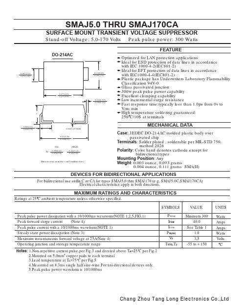
SMAJ5.0 THRU SMAJ170CA
SURFACE MOUNT TRANSIENT VOLTAGE SUPPRESSOR
Stand-off Voltage: 5.0-170 Volts
DO-214AC
Peak pulse power: 300 Watts
施耐德 APC SMV系列750, 1000, 1500, 2000, 3000 VA说明书
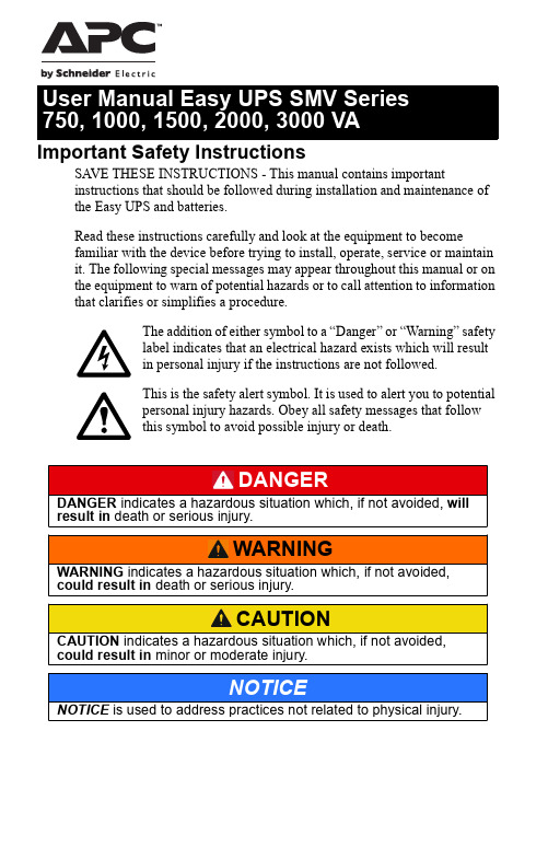
Important Safety InstructionsSAVE THESE INSTRUCTIONS - This manual contains importantinstructions that should be followed during installation and maintenance of the Easy UPS and batteries.Read these instructions carefully and look at the equipment to becomefamiliar with the device before trying to install, operate, service or maintain it. The following special messages may appear throughout this manual or on the equipment to warn of potential hazards or to call attention to information that clarifies or simplifies a procedure.The addition of either symbol to a “Danger” or “Warning” safetylabel indicates that an electrical hazard exists which will resultin personal injury if the instructions are not followed.This is the safety alert symbol. It is used to alert you to potentialpersonal injury hazards. Obey all safety messages that followthis symbol to avoid possible injury or death.Easy UPS SMV Series 750, 1000, 1500, 2000, 3000 VA2Product Handling GuidelinesSafety and General InformationGeneral safety• Adhere to all national and local electrical codes.• This UPS is for indoor use only. To prevent the risk of fire or electric shock, install in temperature and humidity controlled indoor area, free of conductive contaminants.Easy UPS must be installed indoor with controlled environment free of excessive dust, corrosive air or conductive dust. Keep out of direct sun light, water and heat sources.• Place the unit on the stable floor.• Be sure that the mains socket outlet that supplies the UPS is installed near the UPS and easily accessible. Avoid using extension cords.• UPS must be connected to an earthed mains socket outlet.• Connect the power cable directly to a wall outlet. Do not use surge protectors or extension cords.• CAUTION : This UPS is designed to satisfy the requirement of PCs only.• Do not connect printers, heaters, or copiers to the UPS.Battery safety<18 kg <40 lb 18-32 kg 40-70 lb 32-55 kg 70-120 lb >55 kg >120 lb• Servicing of user replaceable batteries should be performed orsupervised by personnel knowledgeable about batteries and requiredprecautions.NOTE: In this case batteries are not user replaceable.• When replacing battery the UPS must be off, and its AC inletunplugged.• CAUTION: Do not dispose of batteries in a fire. The batteries mayexplode.• CAUTION: Do not open or mutilate batteries. Released material isharmful to the skin and eyes and may be toxic.• CAUTION: A battery can present a risk of electrical shock and burns byhigh short-circuit current. Contact with any part of a grounded batterycan result in electrical shock. The following precautions should beobserved when working on batteries.–Remove watches, rings or other metal objects.–Use tool with insulated handles.–Wear rubber gloves and boots.–Do not lay tools or metal parts on top of batteries.–Disconnect the charging source prior to connecting or disconnectingbattery terminals.–Determine if battery is inadvertently grounded. If inadvertentlygrounded, remove source from ground. Contact with any part of agrounded battery can result in electrical shock. The likelihood of suchshock can be reduced if such grounds are removed during installationand maintenance.• CAUTION: The UPS contains internal batteries and may present ashock hazard even when disconnected from AC power.• CAUTION: Battery circuit is not isolated from AC input, hazardousvoltage may exist between battery terminals and ground. Test beforetouching.• CAUTION: Failed batteries can reach temperatures that exceed theburn thresholds for touchable surfaces.Radio Frequency WarningThis is a category C2 UPS product. In a residential environment, this product may cause radio interference, in which case the user may be required to take additional measures.Easy UPS SMV Series 750, 1000, 1500, 2000, 3000 VA3Package Contents4Easy UPS SMV Series 750, 1000, 1500, 2000, 3000 VARear Panel FeaturesEasy UPS SMV Series 750, 1000, 1500, 2000, 3000 VA5Front Panel FeaturesFront panel display6Easy UPS SMV Series 750, 1000, 1500, 2000, 3000 VAEasy UPS SMV Series 750, 1000, 1500, 2000, 3000 VA7Start UpConnect batteryThe battery connector is located on the rear panel. Refer to “Rear Panel Features” on page 5 for details.NOTE : Connect prior to operation.Disconnect prior to transportation. Turn off the UPS and remove input power cable before disconnecting the battery connector. Connect equipment and input power to Easy UPS1. Connect equipment to the battery backup outlets of Easy UPS.2. Plug the Easy UPS power cord directly into a wall outlet, not into asurge protector or power strip.3. Press the POWER ON /OFF button to turn on the unit.NOTE : The Easy UPS should charge the battery for at least 8 hours to ensure sufficient runtime.4. Press the POWER ON /OFF button in 1~3 seconds. Confirm that theEasy UPS is on and is providing power to outlets.Cold start the UPSUse the cold start feature to supply power to connected equipment from the UPS batteries when the UPS is off and there is no power utility.• Press the POWER ON /OFF button. The display panel will illuminate.• Press the POWER ON /OFF button again to supply battery power to the connected equipment.Connect and install management softwareEasy UPS is provided with management software forunattended operating system shutdown, UPSmonitoring, and UPS settings.Refer to for more information. SpecificationsModel SMV750I-MSX SMV1000I-MSXSMV1500AI-MSXSMV2000AI-MSXSMV3000AI-MSXInput SpecificationsVoltage220/230/240 V ACVoltage range165-290 V AC ± 5 V AC165-295 V AC ± 8 V AC Fuse8 A8 A12 A20 A25 A Frequency range45-65 Hz (auto sensing) ±1 HzOutput specificationsUPS capacity (total)750 V A/525 W1000 VA/700 W1500 V A/1050 W2000 V A/1400 W3000 V A/2100 WRated voltage230 VAC Transfer time Typical 2-6 ms, 12 ms max. Waveform Pure Sinewave BatteryType (Maintenance-free Lead acid)12 V /7 Ah x 212 V /7 Ah x 212 V /10 Ah x 212 V /7 Ah x 412 V /9 Ah x 4Charging time4-6 hours recover to 90% capacity PhysicalDimension (D x W x H)410 x 160 x 220 mm(16.1 x 6.3 x 8.7 in)455 x 180 x 240 mm(18 x 7.1 x 9.4 in)Weight withoutpackage13.6 kg17.8 kg23.5 kg25.2 kgPackaging Dimension (D x W x H)508 x 272 x 339 mm(20 x 10.8 x 13.3 in)604 x 319 x 414 mm(23.8 x 12.5 x 163 in)Easy UPS SMV Series 750, 1000, 1500, 2000, 3000 VA8Easy UPS SMV Series 750, 1000, 1500, 2000, 3000 VA 9Audible Indicators and Status IconsTroubleshootingUse the table below to solve minor installation and operation problems.ModelSMV 750I-MSX SMV 1000I-MSX SMV 1500AI-MSX SMV 2000AI-MSX SMV 3000AI-MSX Weight with package 16.6 kg20.75 kg26.9 kg28.9 kgEnvironment Operating,temperature and humidity 0-90% RH @ 0-40 °C (non-condensing)0-95% RH @ 0-40 °C (non-condensing)Noise level < 45 dB International Protection CodeIP20Problem and/or Possible Cause SolutionEasy UPS will not turn on The Easy UPS is not turned on.Press the POWER ON /OFF button to turn on the Easy UPS.The Easy UPS is not connected to AC power, there is no AC power available at the wall outlet, or the AC power is experiencing a brownout or over voltage condition.Be sure that the power cord is securely connected to the utility power outlet and AC power isavailable at the utility power outlet. Check that the wall outlet is switched on or input fuse works properly.10Easy UPS SMV Series 750, 1000, 1500, 2000, 3000 VAServiceIf the unit requires service, do not return it to the dealer. Follow these steps:1. Review the Troubleshooting section of the manual to eliminate commonproblems.2. If the problem persists, contact APC by Schneider Electric CustomerSupport.a.Note the model number and serial number and the date of purchase.The model and serial numbers are located on the rear panel of theunit.b.Call APC by Schneider Electric Customer Support and a technicianwill attempt to solve the problem over the phone. If this is notpossible, the technician will issue a Returned Material AuthorizationNumber (RMA#).c.If the unit is under warranty, the repairs are free.d.Service procedures and returns may vary internationally. Refer to theAPC by Schneider Electric website for country specific instructions.3. Pack the unit in the original packaging whenever possible to avoiddamage in transit. Never use foam beads for packaging. Damagesustained in transit is not covered under warranty.4. Always DISCONNECT THE UPS BATTERIES before shipping.The United States Department of Transportation (DOT), and theInternational Air Transport Association (IATA) regulations requirethat UPS batteries be disconnected before shipping. The internalbatteries may remain in the UPS.5. Write the RMA# provided by Customer Support on the outside of thepackage.6. Return the unit by insured, pre-paid carrier to the address provided byCustomer Support.Easy UPS SMV Series 750, 1000, 1500, 2000, 3000 VA11© 2020 APC by Schneider Electric. APC, the APC logo, and Easy UPS areowned by Schneider Electric Industries S.A.S., or their affiliated companies. All other trademarks are property of their respective owners.EN 990-9144811/2020WarrantyRegister your product on-line The standard warranty is two (2) years from the date of purchase. SEITstandard procedure is to replace the original unit with a factoryreconditioned unit. Customers who must have the original unit back due to the assignment of asset tags and set depreciation schedules must declaresuch a need at first contact with an SEIT Technical Support representative.SEIT will ship the replacement unit once the defective unit has beenreceived by the repair department, or cross-ship upon the receipt of a valid credit card number. The customer pays for shipping the unit to SEIT. SEIT pays ground freight transportation costs to ship the replacement unit to the customer.APC by Schneider Electric IT Customer SupportWorldwideFor country specific customer support, go to the APC by Schneider Electric website, .。
SMCJ40CA中文资料
10 10 10 10 1 1 1 1 1 1 1 1 1 1 1 1 1 1 1 1 1 1 1 1 1 1 1 1 1 1 1 1 1 1 1 1 1 1 1 1 1 1 1 1 1 1
9.2 10.3 11.2 12.0 12.9 13.6 14.4 15.4 17.0 18.2 19.9 21.5 23.2 24.4 26.0 27.6 29.2 32.4 35.5 38.9 42.1 45.4 48.4 53.3 58.1 64.5 69.4 72.7 77.4 82.4 87.1 93.6 96.8 103.0 113.0 121.0 126.0 137.0 146.0 162.0 177.0 193.0 209.0 243.0 259.0 275.0
7.0 7.37 7.98 8.60 9.21 9.83 10.4 11.1 12.3 13.5 14.7 15.9 17.2 18.5 19.7 20.9 22.1 24.5 26.9 29.5 31.9 34.4 36.8 40.6 44.2 49.1 52.8 55.3 58.9 62.7 66.3 71.2 73.7 78.6 86.0 92.1 95.8 104.0 111.1 123.0 135.0 147.0 159.0 185.0 197.0 209.0
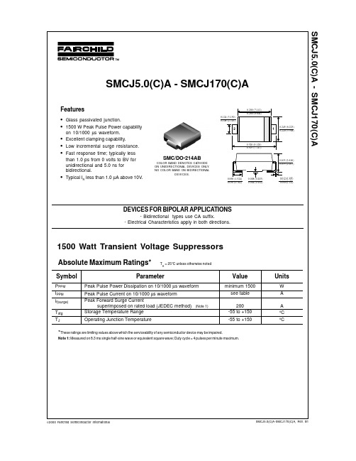
1500 Watt Transient Voltage Suppressors
Absolute Maximum Ratings*
Symbol
PPPM IPPM if(surge) Tstg TJ
TA = 25°C unless otherwise noted
Parameter
Peak Pulse Power Dissipation on 10/1000 µs waveform Peak Pulse Current on 10/1000 µs waveform Peak Forward Surge Current superimposed on rated load (JEDEC method) Storage Temperature Range Operating Junction Temperature
各种IC型号及重要参数(精)

导航菜单公司简介公司新闻产品及服务商机信息人才招聘留言反馈深圳市鑫利发电子有限公司『商机信息』商机主题:鑫利发电子供应各种IC电路!供求方向:供应关键字:IC规格:原装数量:0价格:0发布日期:2010-06-11 15:56:24有效日期:2017-04-14 21:37:38阅读次数:2188描述:PIC12C508A 大量现货 DIP8 05/06+PIC12C509A 大量现货 DIP8 05/06+PIC12F508 大量现货 DIP8 05/06+PIC12F629 大量现货 DIP8 05/06+PIC12F675 大量现货 DIP8 05/06+PIC16C54 大量现货 DIP18 05/06+PIC16C57 大量现货 DIP28宽 05/06+PIC16F54 大量现货 DIP18 05/06+PIC16F57 大量现货 DIP28 05/06+PIC16F630 大量现货 DIP14 05/06+PIC16F676 大量现货 DIP14 05/06+PIC16F84A 大量现货 DIP18 05/06+PIC16F628 大量现货 DIP18 05/06+PIC16F628A 大量现货 DIP18 05/06+PIC16F72 大量现货 DIP28窄 05/06+PIC16F73 大量现货 DIP28窄 05/06+2N3904S KEC SOT-23 05/06+2N3906S KEC SOT-23 05/06+MPS8050D KEC TO-92 05/06+MPS8550D KEC TO-92 05/06+KTC9014C KEC TO-92 05/06+KTC9015C KEC TO-92 05/06+KTC8050D KEC TO-92 05/06+2SC1623 NEC L6 05/06+2SC4226 NEC R24/R25 05/06+BAT85 1500 PHILIPS SMD 5BAV199 100000 PHILIPS SOT23 5BAV23 100000 PHILIPS SOT143 05+BAV23S 100000 PHILIPS SOT23 05+BAV70 10000 PHILIPS SOT23 5BAV99 100000 PHILIPS SOT23 5BAW56 800k PHILIPS SOT23 5BB145B 100000 PHILIPS SOD523 05+BB148 100000 PHILIPS SOD323 05+BB149 100000 PHILIPS SOD323 05+BB155 100000 PHILIPS SOD323 05+BB156 100000 PHILIPS SOD323 04+BB187 100000 PHILIPS SOD523 05+BB555 100000 INFINEON SOD323 05+BB804 100000 INFINEON SOD323 05+BC807-16 100000 PHILIPS SOT23 04+BC807-25 100000 PHILIPS SOT23 5BC807-40 100000 PHILIPS SOT23 5BC817-16 100000 PHILIPS SOT23 5BC817-25 100000 PHILIPS SOT23 5BC817-25W 3000 PHILIPS SMD 05+BC817-40 100000 PHILIPS SOT23 5BC817-40W 33000 PHILIPS SMD 05+BC817W 15000 PHILIPS SMD 05+BC846B 10000 PHILIPS SOT23 5BC847A 100000 PHILIPS SOT23 5BC847发送合作加入询盘车返回打印本页深圳市鑫利发电子有限公司技术支持:顶峰商业服务网© 2004-201031157。
KH-5G-SMAJ-131MM 天线产品规格书说明书

产品规格书Product Specification产品名称: 天线产品型号: K H-5G-SMAJ-131MM 规格描述:5G ,SMA-J ,胶棒版 本 : A01日 期 : 2020/07/17客户承认Customer Approve:制 作drawing 审 核check 批 准approved 陈星 向金保贺俊驹客户确认/日期1.工程图纸Product Drawing深圳市金航标电子有限公司2.产品规格Product Specification射 频 性能 参 数频率范围(MHZ )824-960/1710-2680/ 3400-3600/4800-4900电压驻波比 ≤3.0 增益(dBi ) 3.0 辐射方式 全向 极化方式 垂直极化 输入阻抗(Ω) 50 最大功率(W )10机 械 性 能 参 数接口形式 SMA-J 天线长宽(MM )171*19.5环 境 参 数工作温度 -30℃~60℃ 工作湿度40~85%3.S11测试数据4.增益和效率测试数据5.可靠性试验报告项目测试条件规格储存环境在没有指定的情况下测试温度、湿度、气压如下:1.温度为-40℃~+85℃2.相对湿度为45%-85%3.气压为86kpa-106kpa电气机械性能正常高低温试验在70℃与-40℃之间进行5次循环,然后在正常条件下1-2H,检查外观质量。
尺寸应满足规定并应满足满足于机械、电气性能耐恒定湿热试验相对湿度95±3%,试验温度:40℃.持续2H作用后,试品取出后5min之内测定电气性能,试品在正常条件下1-2H,检查外观质量尺寸应满足规定并应满足满足于机械、电气性能振动试验振频范围10-55HZ,位移幅值:0.35MM,加速度幅值:50.0M/S,扫频循环次数:30次电气机械性能正常跌落试验1M高空按照互相垂直的轴方向自由跌落3次电气机械性能正常测试设备及原理1.测试设备:网络分析仪Network Analyzers :Agilent 8753D 5071B综合测试仪Communications Test Set: Agilent E5515C3D暗室测试系统 3D Chamber Test System:2.测试原理:。
贴片二极管封装

贴片二极管封装各位读友大家好,此文档由网络收集而来,欢迎您下载,谢谢MMBD4148贴片式-SOT封装-二极管SOT-23 Plastic-Encapsulate DiodesElectrical Ratings @TA=25℃ParameterReverse Breakdown V oltageTyp.Max.ConditionsV (BR) RIR=100μAIF=1mA IF=10mAForward voltageVF3IF=50mA VF4IF=150mA IR1μR=75V IR2VR=20V VR=0V,f=1MHz CTIF=IR=10mAtrrIrr=,RL=100ΩReverse currentCapacitance between terminals Reverse Recovery Time贴片元件封装-电阻,电容,电感,二极管,三极管,IC贴片元件封装1电阻最为常见的有0201、0402、0805、0603、1206、1210、1812、2016、2512几类1)贴片电阻的封装与尺寸如下表:英制(mil) 公制(mm) 长(L)(mm) 宽(W)(mm) 高(t)(mm) 0201 0603 ±±±0402 1005 ±±±0603 1608 ±±±0805 2016 ± ± ± 1206 3216 ± ± ± 1210 3225 ±±±1812 4832 ±±±2016 5025 ±±±2512 6432 ± ± ± 2)贴片电阻的封装、功率与电压关系如下表:英制(mil)公制(mm)额定功率@ 70°C 最大工作电压(V) 0201 06031/20W 25 040210051/16W 50 060316081/10W 50 080520161/8W 150 1206 32161/4W 2001210 32251/3W 200 181248321/2W 200 201650253/4W200 251264321W 200 3)贴片电阻的精度与阻值贴片电阻阻值误差精度有±1%、±2%、±5%、±10%精度,J -表示精度为5%、F-表示精度为1%。
瞬雷电子TVS瞬态抑制二极管SMAJ系列
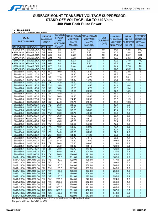
DEVICES FOR BIPOLAR APPLICATION For Bidirectional use C or CA Suffix for types SMAJ5.0 thru types SMAJ170 (e.g. SMAJ5.0C , SMAJ170CA)
Electrical characteristics apply in both directions
at terminals
Dimensions in inches and(millimeters)
◎ Plastic package has Underwriters Laboratory
Flammability 94V-O ◎ Pb-free plated MECHANICAL DATA Case: JEDEC DO-214AC. Molded plastic over glass passivated junction Terminal: Solderable per MIL-STD-750, Method 2026 Polarity: Color band denoted positive end (cathode) except Bidirectional Standard Packaging: 12mm tape (EIA STD RS-481) Weight: 0.002 ounce, 0.061 gram
0.012 (0.305) ◎ Repetition Rate (duty cycle):0.01% 0.006 (0.152) ◎ Fast response time: typically less than 1.0ps from
0 Volts to V(BR) for unidirectional types
- 1、下载文档前请自行甄别文档内容的完整性,平台不提供额外的编辑、内容补充、找答案等附加服务。
- 2、"仅部分预览"的文档,不可在线预览部分如存在完整性等问题,可反馈申请退款(可完整预览的文档不适用该条件!)。
- 3、如文档侵犯您的权益,请联系客服反馈,我们会尽快为您处理(人工客服工作时间:9:00-18:30)。
10
1
10
100
1000
VWM, STANDOFF VOLTAGE (V) Fig. 2 Typical Junction Capacitance
IP, PEAK PULSE CURRENT (%Ipp)
Pd, PEAK PULSE POWER (kW)
Tj = 25°C
Non Repetitive Pulse Waveform Shown in Fig. 4
Mechanical Data
· · · ··
A
C
A B C D E G H J
D
J
H
G E
All Dimensions in mm
Maximum Ratings
Characteristic Peak Pulse Power Dissipation (Non repetitive current pulse derated above T = 25°C) A (Note 1) Peak Forward Surge Current, 8.3ms Single Half Sine Wave Superimposed on Rated Load (JEDEC Method) (Notes 1, 2, & 3) Instantaneous Forward Voltage @ IPP = 35A (Notes 1, 2, & 3) Operating and Storage Temperature Range Notes:
100
tr = 10ms Peak Value Ipp
10
Half Value Ipp/2
50
1.0
tp
0.1 0.1 1.0 10 100 1000 10000
0
10 X 1000 Waveform as defined by R.E.A.
0
1
2
3
tp PULSE WIDTH (ms) Fig. 3 Pulse Rating Curve
DS19005 Rev. 9 - 2
1 of 3
SMAJ5.0(C)A - SMAJ170(C)A
元器件交易网
Part Number Add C For Bi-Directional (Note 4) SMAJ5.0(C)A SMAJ6.0(C)A SMAJ6.5(C)A SMAJ7.0(C)A SMAJ7.5(C)A SMAJ8.0(C)A SMAJ8.5(C)A SMAJ9.0(C)A SMAJ10(C)A SMAJ11(C)A SMAJ12(C)A SMAJ13(C)A SMAJ14(C)A SMAJ15(C)A SMAJ16(C)A SMAJ17(C)A SMAJ18(C)A SMAJ20(C)A SMAJ22(C)A SMAJ24(C)A SMAJ26(C)A SMAJ28(C)A SMAJ30(C)A SMAJ33(C)A SMAJ36(C)A SMAJ40(C)A SMAJ43(C)A SMAJ45(C)A SMAJ48(C)A SMAJ51(C)A SMAJ54(C)A SMAJ58(C)A SMAJ60(C)A SMAJ64(C)A SMAJ70(C)A SMAJ75(C)A SMAJ78(C)A SMAJ85(C)A SMAJ90(C)A SMAJ100(C)A SMAJ110(C)A SMAJ120(C)A SMAJ130(C)A SMAJ150(C)A SMAJ160(C)A SMAJ170(C)A Reverse Standoff Voltage VRWM (V) 5.0 6.0 6.5 7.0 7.5 8.0 8.5 9.0 10 11 12 13 14 15 16 17 18 20 22 24 26 28 30 33 36 40 43 45 48 51 54 58 60 64 70 75 78 85 90 100 110 120 130 150 160 170 Breakdown Voltage VBR @ IT (Note 5) Min (V) 6.40 6.67 7.22 7.78 8.33 8.89 9.44 10.0 11.1 12.2 13.3 14.4 15.6 16.7 17.8 18.9 20.0 22.2 24.4 26.7 28.9 31.1 33.3 36.7 40.0 44.4 47.8 50.0 53.3 56.7 60.0 64.4 66.7 71.1 77.8 83.3 86.7 94.4 100 111 122 133 144 167 178 189 Max (V) 7.25 7.37 7.98 8.60 9.21 9.83 10.4 11.1 12.3 13.5 14.7 15.9 17.2 18.5 19.7 20.9 22.1 24.5 26.9 29.5 31.9 34.4 36.8 40.6 44.2 49.1 52.8 55.3 58.9 62.7 66.3 71.2 73.7 78.6 86.0 92.1 95.8 104 111 123 135 147 159 185 197 209 Test Current IT(mA) 10 10 10 10 1.0 1.0 1.0 1.0 1.0 1.0 1.0 1.0 1.0 1.0 1.0 1.0 1.0 1.0 1.0 1.0 1.0 1.0 1.0 1.0 1.0 1.0 1.0 1.0 1.0 1.0 1.0 1.0 1.0 1.0 1.0 1.0 1.0 1.0 1.0 1.0 1.0 1.0 1.0 1.0 1.0 1.0 Max. Reverse Leakage @ VRWM (Note 6) IR (mA) 800 800 500 200 100 50 10 5.0 5.0 5.0 5.0 5.0 5.0 5.0 5.0 5.0 5.0 5.0 5.0 5.0 5.0 5.0 5.0 5.0 5.0 5.0 5.0 5.0 5.0 5.0 5.0 5.0 5.0 5.0 5.0 5.0 5.0 5.0 5.0 5.0 5.0 5.0 5.0 5.0 5.0 5.0 Max. Clamping Max. Peak Pulse Current Voltage @ Ipp I
pp
Marking Code BITE TG TK TM TP TR TT TV TX TZ UE UG UK UM UP UR UT UV UX UZ VE VG VK VM VP VR VT VV VX VZ WE WG WK WM WP WR WT WV WX WZ XE XG XK XM XP XR UNIHE HG HK HM HP HR HT HV HX HZ IE IG IK IM IP IR IT IV IX IZ JE JG JK JM JP JR JT JV JX JZ RE RG RK RM RP RR RT RV RX RZ SE SG SK SM SP SR
元器件交易网
SMAJ5.0(C)A - SMAJ170(C)A
400W SURFACE MOUNT TRANSIENT VOLTAGE SUPPRESSOR Features
· · · · · · · 400W Peak Pulse Power Dissipation 5.0V - 170V Standoff Voltages Glass Passivated Die Construction Uni- and Bi-Directional Versions Available Excellent Clamping Capability Fast Response Time Plastic Material: UL Flammability Classification Rating 94V-0 Case: SMA, Transfer Molded Epoxy Terminals: Solderable per MIL-STD-202, Method 208 Polarity Indicator: Cathode Band (Note: Bi-directional devices have no polarity indicator.) Marking: Date Code and Marking Code See Page 3 Weight: 0.064 grams (approx.)
t, TIME (ms) Fig. 4 Pulse Waveform
Ordering Information
Device
(Note 4) Packaging SMA Shipping 5000/Tape & Reel
SMAJXXX(C)A-13 Notes:
4. For Packaging Details, go to our website at /datasheets/ap02007.pdf.
VC (V) 9.2 10.3 11.2 12.0 12.9 13.6 14.4 15.4 17.0 18.2 19.9 21.5 23.2 24.4 26.0 27.6 29.2 32.4 35.5 38.9 42.1 45.4 48.4 53.3 58.1 64.5 69.4 72.7 77.4 82.4 87.1 93.6 96.8 103 113 121 126 137 146 162 177 193 209 243 259 275
@ TA = 25°C unless otherwise specified Symbol PPK IFSM VF Tj, TSTG Value 400 40 3.5 -55 to +150 Unit W A V °C
B
Dim
SMA Min 2.29 4.00 1.27 0.15 4.80 0.10 0.76 2.01 Max 2.92 4.60 1.63 0.31 5.59 0.20 1.52 2.62
1000
Unidirectional
50
Bidirectional