CANopen教程
CANopen用户手册:线性传感器说明书

Content1CANopen 2 1.1EDS Files 2 1.2Support 2 1.3Features 2 1.3.1Basic information 2 1.3.2Basics based on CiA DS-301, V4.2.0 2 1.3.3Basics based on CiA DSP-406, V3.2 3 1.3.4Basics SDO communication 3 1.3.5Basics PDO communication based on CiA 301, V4.2.0 3 1.4Object Library 4 1.4.1Communication Profile Area based on DS 301 V4.2.0 4 1.4.2Device Profile Area 6 1.4.3Manufacturer specific Area 8 1.5Explanations to Object Library 9 1.5.1Object 0x6300 Encoder Cams 9 1.5.2Cam state registers 9 1.5.3Object 0x6400 Work Area 9 1.5.3.1Work Area Supervision 9 1.5.3.2Work Area State 9 1.6LSS / Layer Setting Service 9 1.6.1Configuration of Node-ID 10 1.6.2Configuration of Bit Rate 10 1.6.3Store Configuration Data 11 1.7SDO Services 11 1.7.1SDO Download 11 1.7.2SDO Upload 12 1.7.3SDO Abort 12 1.8Process Data PDO 12 1.8.1PDO Default Setting 12 1.8.2PDO Parameter Setting 12 1.9Error Handling 14 1.9.1Emergency Messages 14 1.10Error Objects 15 1.10.1Manufacturer-specific Status 15 1.11Non-Volatile Storage and Data Restoration 16 1.12Abbreviations 17 1.13Document Changes 171 CANopenThis document reflects the Novotechnik sensor protocol implementation of the standard CANopen protocol.A basic knowledge of the CAN Bus is required for a proper understanding of this document.Most of the definitions made are according to the following CiA Standard specifications.For making use of all the features that these specifications offer, a knowledge about them is absolutely necessary. The sensor supports the CANopen Communication profile DS-301, V4.2.0, Encoder profile DSP-406, V3.2 and Layer Setting Services (LSS) DSP-305, V1.1.2.1.1 EDS FilesFor integration in a common CANopen projecting tool, electronic data sheet (*.eds) files are provided.These files can be downloaded from the Novotechnik Web Site, see Downloads/Operating manualswhere also this document can be found.Electric data sheet see file Product series_CANopen.1.2 SupportIfyouhaveanyquestions,******************************************************.Electronic data sheets or user manuals for previous software versions are available on request.1.3 Features1.3.1 Basic informationVendor ID: 386 = 0x0182 (Novotechnik)Product code: TP1: 04035 = 0x0FC3, TH1: 04042 = 0x0FCA, TM1: 04228 = 0x1084, TF1: 04052 = 0x0FD4 Rev.-No.: f.e 196613 = 0x30005Serial No.: see product label, “YYMMxxxx”1.3.2 Basics based on CiA DS-301, V4.2.01.3.3 Basics based on CiA DSP-406, V3.21.3.4 Basics SDO communication1.3.5 Basics PDO communication based on CiA 301, V4.2.01.4 Object Library1.4.1 Communication Profile Area based on DS 301 V4.2.01) for 1 position marker2) for 2 position markers1.4.2 Device Profile Area* for 1 position marker: default value 0x01** for 1 position marker and product series TM1 / TF1: not available 1.4.3 Manufacturer specific Area1.5 Explanations to Object Library1.5.1 Object 0x6300 Encoder CamsEncoder cams are used to indicate if a position falls below or exceeds a defined value.1.5.2 Cam state registersCam active: the current position value is between the higher and lower cam-limitCam inactive: the current position value is not between the higher and lower cam-limit.The values for low limit (0x631x) and high limit (0x632x) regard the values for preset (0x6010) and measuring steps (0x6005). The value of hysteresis (0x633x) is added in direction of motion.Note: the cam high limit value can have a lower value than the cam low limitA change in cam state causes an EMCY message.The cam state objects (0x6300) are able to be mapped to the TPDOs.1.5.3 Object 0x6400 Work AreaIt is possible for encoders to define a so-called user defined working area.The main purpose for a work area is to get a high-priority information (via EMCY message) when the transducer’s p o-sition leaves its predefined working area.The actual work area information with work area low limit and work area high limit may be stored in object 0x6401 and 0x6402. This way, the area state object (0x6400) may also be used as software limit switches.1.5.3.1 Work Area SupervisionEach work area channel is fixedly linked to a position channel:1.5.3.2 Work Area StateThe values for low limit (0x6401) and high limit (0x6402) regard the values for preset (0x6010) and scaling (0x6501, 0x6502).A change in work area state causes an EMCY message.The work area state objects (0x6400) are able to be mapped to the TPDOs.1.6 LSS / Layer Setting ServiceTo configure the encoder via the LSS(according CiA DS 305) the encoder is handled as a slave, thePLC must have a LSS master functionality.A LSS-message is composed as follows:This applies to the COB-ID:• LSS-Master ⇒ LSS-Slave: 2021 (0x7E5)• LSS-Slave ⇒ LSS-Master: 2020 (0x7E4)LSS can only be used when the encoder is in the stopped status or pre-operational status.The NMT command for setting the encoder in stopped status is:To program via LSS the sensor has to be switched to LSS configuration state.There are two possible ways to do so:• Switch Mode Selective:only the addressed CANopen device is switched to the LSS configuration stateLSS requires data content in the following objects:Example:Vendor-ID (see index 1018/1) 0x0182 LSS-Command 0x40 Product code (see index 1018/2) 0x0BE0 LSS-Command 0x41 Rev.No. (see index 1018/3) 0x10003 LSS-Command 0x42 Serial-No. (see index 1018/4) 0x12345678 LSS-Command 0x43 After receiving the identification objects, the encoder answers with LSS-Command 0x44.• Switch Mode Global: all CANopen devices supporting LSS are switched to the LSS configuration stateWhen the CAN devices are in configuration state the Node-ID and/or the bit rate can be changed. 1.6.1 Configuration of Node-IDThe Node-ID can be programmed with the LSS-Command 0x11N ID: new Node-ID in the range of 1 (127)Err Code: 0: protocol successfully completed / 1: Node-ID out of rangeChange of Node-ID will cause:•Automatic alteration of COB-ID’s for SDO1, EMCY and Heartbeat and TPDOs.•Non-volatile Node-ID storage through …Store Configuration“ in the LSS mode configur ation.1.6.2 Configuration of Bit RateThe Bit Rate can be programmed with LSS-Command 0x13Table Index: 0x07: 20 kBaud0x06: 50 kBaud0x04: 125 kBaud0x03: 250 kBaud0x02: 500 kBaud0x01: 800 kBaud0x00: 1000 kBaudErr Code: 0: protocol successfully completed 1: Bit timing not supportedChange of Bit rate will cause:•The bit rate gets active•Non-volatile CAN bit rate storage through …Store Configuration“ in the LSS mode configuration1.6.3 Store Configuration DataThe LSS configuration data (Node-ID and Bit Rate) are stored to the non-volatile memory of the sen-sor using LSS-Command 0x17Err Code: 0: protocol successfully completed 2: storage media access error1.7 SDO ServicesService Data Objects SDO (according to CiA DS 301) manage the parameter data exchange, e.g. thenon-cyclical execution of the preset function.Parameters of device object library (object index/subindex see chapter 1.4 Object Library) can beread, written or stored by means of SDO.1.7.1 SDO DownloadThe SDO download service is used to configure the parameters.Command 0x2_: 0x22 write command, parameter to encoder0x23 write command, 4 Byte parameter to encoder0x27 write command, 3 Byte parameter to encoder0x2B write command, 2 Byte parameter to encoder0x2F write command, 1 Byte parameter to encoderCommand 0x60: confirmation: parameter receivedNODE-IDUsing writing to object 0x2000, non-volatile storage has to be done by w riting the“save”- signature (0x65766173) on object 0x1010/1 (TP1/TH1) or 0x1010/4 (TF1). These changes will become effective after a communication restart or a power up.Changing the Node-ID will affect all COB-IDs according to the “predefined co nnection s et”.Example: COB-ID TPDO1 = 0x180 + (Node-ID)BIT-RATEUsing writing to object 0x2001; non-volatile storage has to be done by writing the“save”- signature (0x65766173) on ob-ject 0x1010/1 (TP1/TH1) or 0x1010/4 (TF1). These changes will become effective after a communication restart or a power up.1.7.2 SDO UploadThe SDO upload service is used to read the parameters.Command 0x40: read command, parameters from encoderCommand 0x4_: 0x42 read command, parameter to encoder0x43 read command, 4 Byte parameter to encoder0x47 read command, 3 Byte parameter to encoder0x4B read command, 2 Byte parameter to encoder0x4F read command, 1 Byte parameter to encoder1.7.3 SDO AbortIf the SDO download or SDO upload service fails for any reason, the sensor responds with a SDO abort protocol. Abort Code: 0x06090011 subindex does not exist0x06090030 value exceeded0x06020000 object does not exist0x06010001 object is write only0x06010002 object is read only0x06060000 access error0x08000020 data transport error0x08000000 general error0x08000022 wrong state1.8 Process Data PDOProcess Data Objects (according CiA DS 301)manage the process data exchange, f.e the cyclical transmission of the position value. The process data exchange with the CANopen PDOs is a very slim process without protocol overhead.1.8.1 PDO Default Setting2 Transmit PDOs (TPDO) with each max. 8 bytes are provided:0x1800 TPDO1: default: Event-driven with event timer switched off (changeable to synchronous)0x1801 TPDO2: default: synchronous1.8.2 PDO Parameter SettingThe contents of the encoder-specific TPDOs can be configured by variable mapping according to cus-tomer´s requirements. This mapping has to be performed for the encoder as well as for the receiver.The PDO is limited to a maximum size of 8 bytes and 5 mappings per each PDO.Step 1: For changing of mapping, the sensor must be in properational mode and the MSB of PDOCOB-ID has to be set to 1 to deactivate it.Step 2: Clearing entries in mapping table of PDO1 (PDO2) => subindex 0x0 of object 1A00 (1A01)has to be set to 0x00.Step 3: Mapping of objects into PDOExample:A PDO shall be mapped in a way that the "current position", the "current speed" and the "current chiptemperature" are transmitted in one PDO .Mapping #1 “current position”:Mapping #2 “current speed”:Mapping #3: “current chip temperature”.Step 4: Setting entries in mapping table => subindex 0x0 of object 1A00 has to be set to the numbers of mapping en-tries (e.g. 0x03)Step 5: For re-activating the PDO, the MSB of PDO COB-ID has to be set to 0.Note:TPDO1 value for Event Timer must always be higher than the value for Inhibit Time (except for value 0).Failed sending of TPDOs can occur if:•more TPDOs shall be sent than the CANbus may accept due to insufficient CAN bit rate compared to TPDO/Event Timer •excessive bus load or unfavourable setting of COB-ID in the CANopen network prevents TPDOsending•Object 0x1800/5- event timer- is set to 0.1.9 Error HandlingDepending on the type of error occured, the sensor will react accordingly:* according to DS-301, see chapter 1.7 SDO Services** details see chapter 1.9.1 Emergency Messages1.9.1 Emergency MessagesCOB-ID EMCY in object 0x1014.Error-Register in object 0x1001.0x50xx Device Hardware 0x60xx Device Software 0x80xx Monitoring 0x90xx External Error1.10 Error Objects1.10.1 Manufacturer-specific StatusThe object 0x1002 shows the sensor status bit code and is used for internal process control purposes. For servicing this information can be requested via SDO (see chapter 1.7 SDO Services).Bit Definition (if bit value = 1)2 CAN Bus-Off Timer started0-1 NMT Condition of Sensor%11 stopped%10 operational%01 pro-operational%00 initialisation1.11 Non-Volatile Storage and Data RestorationDefault values for all data objects are stored in the non-volatile program memory.Data encryption to the non-volatile memory is only admitted in the pre-operational status.• Storage via LSS:Data must be stored through the LSS Service Configuration/Store while in LSS Configuration Mode (see chapter 1.6 LSS / Layer Setting Service)• Storage via SDO:Object 0x1010:Data is stored in the non-volatile memory during encryption of object 0x1010 with …save“ signature (0x65766173).Object 0x1011:Encryption of object 0x1011 with the sig nature …load“ (0x64616F6C) will upload data from the non-volatile memory. Default settings are being restored (see chapter 1.7 SDO Services).CAUTION: In case of custom programmed parameters like node-ID, averaging, bit rate etc. these will be reset to default in case of the corresponding reset command below (default values see chapter 1.4 Object Library).Object 0x1010 Object 0x1011 Subindex /1AllSubindex /2CommunicationSubindex /3ApplicationSubindex /4ManufacturerCOB-ID SyncGuard Time X XLife Time Factor X XHeartbeat Timer X XTPDO COB-ID D XTPDO Trans Typ X XTPDA Inhibit Time X XTPDO Event Timer X XTPDO Mapping X XNMT Startup X XNode-ID X (TP1/TH1) X (TF1) BitRate X (TP1/TH1) X (TF1) Number of position markers (only TP1 / TH1) XCustom (only TP1 / TH1) X Operating Parameters X XLinear Encoder Measuring Step Settings X XPreset Value X XCAM Enable X XCAM Polarity X XCAM Low Limit X XCAM High Limit X XCAM Hysterese XWork Area Low Limit XWork Area High Limit XX: data saved or restoredD: data set to default value• Delete via SDO Object 0x1010:Additionally to the functionality defined in CiA standard DS-301, CANopen library offers the possibility to delete data inthe non-volatile memory. Del ete process is initiated by sending the signature “kill” (0x6C6C696B) to object 0x1010.• Manufacturing Mode Object 0x1010▪Only TM1 series:If the sensor is out of function and the signature “boot” 0x746F6F62 in object 0x1000 (device type) is active, the sensor is in manufacturing mode. This mode can be left by power off-on or via the operationalcommand.1.12 AbbreviationsCAN Controller Area Networkch channelCOB-ID Communication Object Identifierconst constant parameter, only readableDLC Data Length CodeDS Draft StandardEMCY Emergency ServiceNMT Network-ManagementPDO Process Data ObjectPos Position (value)ro read only, parameter can changerw read/writeRx Novotechnik sensor is consumer of the CAN data frameRTR Remote Transmission RequestSDO Service Data ObjectSYNC Synchronisation messageTPDO Transmit Process Data ObjectTx Novotechnik sensor is producer of the CAN data frame1.13 Document ChangesRevision Changes Date WhoV00 First edition 16.07.14 VM/mm V07 1.2.5 / 1.3.1 object 1801x2: event driven transmission deleted for TPDO2. 1.3.1 objects:TPDO1 and TPDO2: name modified. 1.3.object 1800/2 and 1801/2 comment: synchronous1...240 instead 1...239, TPDO off: 0 added01.04.20 VM/mmV08 1.3.1 object 1010/4 user parameter data instead of manufacturer defined parameters.1.3.1 1010/5 added (Manufacturer data parameter). 1.10. signature kill 6C6C696B insteadof 6B696C6C, comment regarding manufacturing mode added21.01.21 VM/mmV09 1.2 Support added, all further chapter numbers changed1.8.3 Textual modifications 07.09.2117.11.22VM/mm。
L6C系列CANopen技术指导手册

L6C系列CANopen技术指导手册目录1 端口连接及设置 (3)1.1CAN总线连接器 (3)1.2L6C系列通讯参数设置 (3)2 CANOPEN通讯 (4)2.1CAN OPEN协议概述 (4)2.2L6C系列CAN OPEN通讯服务 (4)2.3CAN OPEN预定义连接集 (5)2.4对象字典(OD) (6)2.4.1 对象字典概述 (6)2.4.2 对象字典结构 (7)2.4.3 对象类型 (7)2.4.4 访问属性 (7)2.4.5 通讯对象字典 (7)2.5网络管理(NMT) (15)2.5.1 NMT模块控制 (15)2.5.2 NMT节点保护 (16)2.5.3 NMT Boot-up (17)2.5.4 NMT通讯状态机 (17)2.6过程数据对象(PDO) (18)2.7服务数据对象(SDO) (20)2.8应急指示对象(E MERGENCY O BJECT) (21)3 CANOPEN设备控制 (21)3.1设备控制框图 (21)3.1.1 操作模式 (22)3.1.2 状态机 (22)3.2对象字典 (23)3.2.1 对象类型 (23)3.2.2 设备控制对象字典 (23)4 L6C系列 CANOPEN操作模式 (30)4.1协议位置模式 (30)4.1.1 脉冲当量 (30)4.1.2 运动设置 (30)4.1.3 查询设置 (30)4.2协议速度模式 (30)4.2.1 运动设置 (30)4.2.2 查询设置 (31)4.3原点模式 (31)4.3.1 运动设置 (31)4.3.2 查询设置 (31)附录 A (32)附录 B (33)附录C (34)参考文献 (35)1 端口连接及设置本章主要介绍雷赛L6C系列伺服驱动器CAN总线连接器的定义及通讯设置。
1.1 CAN总线连接器雷赛L6C系列驱动器CAN总线端口采用的是标准RJ45规范,其端口定义如下:每个引脚定义如下表:提示:在L6C系列驱动器内部硬件电路已经有120欧姆的终端电阻接入,用户不必再附加终端电阻。
关于CANopen通讯模块的使用方法
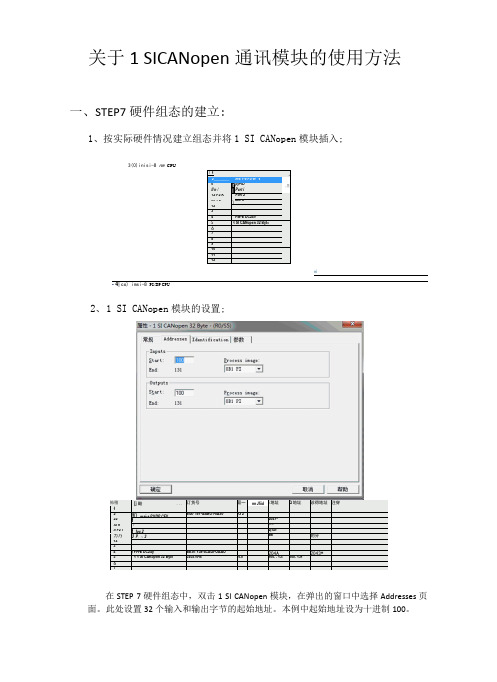
关于1 SICANopen通讯模块的使用方法一、STEP7硬件组态的建立:1、按实际硬件情况建立组态并将1 SI CANopen模块插入;3(0)inisi-8 nm CPU「1A2 ________ ms 1-8 P9/W "VIl n /irIFpjr-iDPert i,三12 P2 K Fort 2X1 P3\Are 31234PM-E DC24V5| 1 SI CANopen 32 Byt<6789101112ni- 4| co) imsi-8 PS/DP CPU怖稽[j 酸...订货号固一nn Jfiid i地址Q地址诊得地址注穿12即msi-s P9/DP CFV6IS7 151-GABO1-0A90Y3 22212047^Xi n *I*/冢如Il P2 l 1 foe 22(X5/力乃J P。
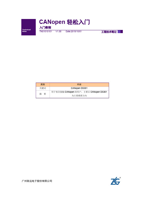
八3aw*的分1234y PH-E DC24y BEST 138-4CAOI-OAAO204A2043*5 1 1 SI CAKopon 32 Byte020570-B VI.0100. . 13!100. 13167在STEP 7硬件组态中,双击1 SI CANopen模块,在弹出的窗口中选择Addresses页面。
此处设置32个输入和输出字节的起始地址。
本例中起始地址设为十进制100。
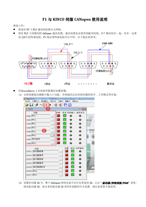
2、1 SI CANopen模块的设置;在性-1 SI CANopen 32 Byte - (R0/S5)常规Addresses | Identification确定选择“参数”页面,设置“Baudrate”以及input/output data size,如上图所示。
PS:理论上Process data mode因为本次传输数据在32 Byte内,可选择Standard模式,但不知道为什么会报错,所以选择Fragmented模式。
双击STEP 7硬件组态中的CPU,选择“周期/时钟存储器”,修改过程映像输入/输出区的大小。
CANopen轻松入门
广州致远电子股份有限公司入门教程 CANopen 轻松入门类别内容 关键词CANopen DS301 摘 要 用于初次接触CANopen 的用户,主要以CANopen DS301为主要教授方向修订历史目录1. 前言 (1)2. CANopen在ISO层级中的位置 (2)3. CANopen协议诞生和发展 (3)4. CANopen的预定义报文ID分类 (5)4.1网络管理(NMT)与特殊协议(Special protocols)报文ID分类 (5)4.2过程数据对象(PDO)和服务数据对象(SDO)的报文ID分类 (7)5. 对象字典OD(Object dictionary) (9)5.1对象字典概述 (10)5.2通讯对象子协议区(Communication profile area) (10)5.3通用通讯对象(General communication objects) (10)5.4制造商特定子协议(Manufacturer-specific Profile) (11)5.5标准化设备子协议(Standardized profile area) (12)5.6对象字典和EDS文件实例 (12)6. 网络管理NMT(Network management) 与CANopen主站 (16)6.1NMT节点状态 (16)6.2NMT节点上线报文 (17)6.3NMT节点状态与心跳报文 (18)6.4NMT节点守护 (18)6.5NMT节点状态切换命令 (19)6.6CANopen主站设备 (20)7. 过程数据对象PDO(Process data object) (22)7.1PDO的CAN-ID定义 (22)7.2PDO的传输形式 (23)7.3PDO的通信参数 (24)7.4PDO的映射参数 (24)8. 服务数据对象SDO(Service data object) (26)8.1通讯原则(communication principle) (26)8.2快速SDO协议(Expedited SDO protocol) (27)8.3普通SDO协议(Normal SDO protocol) (27)9. 特殊协议(Special protocols) (30)9.1同步协议(Sync protocol) (30)9.2时间戳协议(Time-stamp protocol) (31)9.3紧急报文协议(Emergency protocol) (33)10. 免责声明 (35)1. 前言本教程适用于CIA CANopen协议DS301又名CIA301标准。
CANopen教程全解 共36页

请求)
(2)SDO服务数据对象
功能:主要用于主节点对从节点的参数配置。 用来在设备之间传输大的低优先级数据,典型 的是来配置CANopen网络上的设备。
通讯方式:客户机/服务器 它用于访问对象字典的入口。对CANopen对象
表示命令会被广播至所有从节点 任何NMT从设备在上电时都必须主动报告自己上电信
息,便于NMT主设备进行管理。
(4)特殊功能对象
①同步对象 ②紧急对象 ③时间标记对象
①同步对象
功能:由同步生产者向网络进行周期性 的广播,该对象提供基本的网络时钟
通信方式:生产者/消费者模式
②紧急对象
CANopen网络通信和管理是通过不同的通信对象来完 成的。
CANopen协议定义了四种通信对象,分别为过程数据 对象PDO(Process Data Object)、服务数据对象 SDO(Service Data Object)、网络管理对象 NMT(NetWork Management Object)、预定义报文或 者特殊功能对象。
二、通信方式
根据通信对象功能,通信关系可分为以下3类: 主/从关系可以对应NMT SYNC 节点保护等 一
对多,一唯一,可以有应答,也可以没有。 客户机/服务器可以对应SDO 一对一,带应答。 生产者/消费者可以对应PDO Heartbeat等,一
对多,一不唯一,没有应答。
二、通信方式
对于开发主节点和从节点设备来说有着较大的区别, 主节点主要负责整个网络的管理并且能加载所有节点
的EDS(Electronic Data Sheet)文件,例如主节点可
F1与Kinco伺服CANopen异步通讯使用说明
F1与KINCO伺服CANopen使用说明准备工作:●准备好PC与PLC通讯的标准以太网线。
●焊好PLC与伺服间的CANopen通讯电缆,通讯电缆务必使用屏蔽双绞线,2-7脚双绞在一起。
首末一定要加120Ω的终端电阻,F1端自带终端电阻可以不焊。
以下做法供参考:●用KincoServo上位机软件配置好伺服参数:(1)去掉伺服驱动器数字输入口功能,否则通讯无法控制伺服控制字、工作模式等对象。
(2)设置好伺服ID号。
整个CANopen网络里面不允许有重复的ID,点击“驱动器/控制面板/F005”查看/修改驱动器ID。
部分系列驱动器ID采用外部拨码开关设置,请注意查看手册说明。
(3)设置好伺服CANopen通讯波特率。
点击“驱动器/ECAN/其他”菜单,设置伺服驱动器CANopen通讯波特率,如下图所示。
完成准备工作我们就可以开始PLC编程工作了。
CANopen通讯要点:通讯电缆是否正确,终端电阻是否正确,站号是否正确,波特率是否正确,PDO配置是否正确,PDO传输类型是否正确。
1.打开软件新建工程,选择F1,点击OK。
2.根据自己的喜好选择PLC主程序的编程语言,然后点击OK。
3.开始进行CANopen通讯配置前,我们先需要添加伺服从站的EDS文件到Codesys里面来。
点击主菜单栏里的“Extras/add configuration file”选项。
找Kinco伺服的EDS文件,选中文件点击OK。
4.添加CANopen从站,设置通讯参数。
(1)F1有两路CANopen主站,选中其中一个口右键添加伺服从站。
(2)从站添加成功后,设置主站通讯参数。
下图中PLC主站波特率500K,波特率最高可设成1M,主从站波特率要一样;主站Node_ID可以设成0,不能和伺服从站ID重复。
(3)设置伺服从站的通讯参数。
下图中伺服从站的Node_ID设为1,从站Node_ID设置范围1-127,伺服驱动器ID要和这里设置的值一样为1;多个从站时ID要设置的都不一样。
canopen华茂教程
华茂技术部CANopen实现1.简介从OSI网络模型的角度来看,现场总线网络一般只实现了物理层、数据链路层和应用层,CAN现场总线仅仅定义了物理层和数据链路层,实际设计中,这两层完全有硬件来实现。
但是CAN没有规定应用层协议,无法定义CAN报文中11/29位标示符和8字节数据的使用。
因此需要一个开放的、标准化的高层协议,使得协议支持各种CAN厂商设备。
CANopen是基于CAN的一个应用广泛的应用层协议,它提供了网络管理服务和报文传送协议,在保证网络节点互用性的同时允许节点的功能随意扩展。
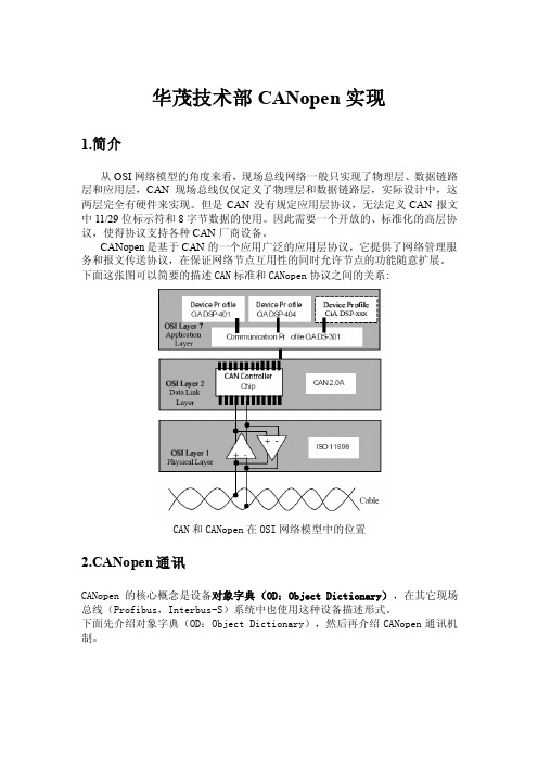
下面这张图可以简要的描述CAN标准和CANopen协议之间的关系:CAN和CANopen在OSI网络模型中的位置2.CANopen通讯CANopen的核心概念是设备对象字典(OD:Object Dictionary),在其它现场总线(Profibus,Interbus-S)系统中也使用这种设备描述形式。
下面先介绍对象字典(OD:Object Dictionary),然后再介绍CANopen通讯机制。
2.1对象字典OD对象字典包含了描述一个设备和它的网络行为的所有参数。
对象字典是一个有序的对象组,每个对象采用一个16位的索引值来寻址,为了允许访问数据结构中的单个元素,还定义了一个8位的子索引,下图为对象字典的索引表:CANopen协议定义的通用对象字典结构表在表中可以看出,索引值从0x0000至0xFFFF,其中0x0000-0x0FFF区域和0x2000-0x5FFF区域是定义好的区域,不能用来开发,可以用来建立设备对象字典的区域为通讯子协议区域和标准的设备子协议区域,例如用于描述运动控制的设备子协议DS402中定义了索引项0x6072为max_torque, 索引项0x6073为max_current, 索引项0x60F8为max_slippage,等等。
CANopen网络中每个节点都有一个对象字典,用来描述当前节点的设备信息、网络行为和参数,在主从网络结构中,主站通过从站的对象字典来查询修改从站的参数或者对从站的网络行为进行指示。
canopen 字典 使用方法

canopen 字典使用方法(原创实用版5篇)《canopen 字典使用方法》篇1CanOpen 字典是一种用于描述CanOpen 设备及其属性的数据结构。
以下是一个CanOpen 字典的使用示例:```pythonimport can# 创建一个CanOpen 字典canopen_dict = {"device_id": "0x1234","mode": "OPMODE1","master_clock": 10000,"driver_reset": 1,"enable": 1,"select": "slot 0","secondary_reset": 0,"power_supply": "6V","output_status": 0,"load_status": 0,"command": "TEST_PATTERN","command_value": 0x5A,"master_clear": 0,"position": 0,"limit": [0, 0, 0],"home": [0, 0, 0],"target": [0, 0, 0],"run_state": 0,"tacho_count": 0,"temperature": -45,"velocity": 0,"actual_velocity": 0,"distance": 0,"actual_distance": 0,}# 发送CanOpen 数据帧data = can.Message(canopen_dict)data.arbitration_id = 0x55data.dlc = len(canopen_dict) - 1data.data = canopen_dict.values()send_can(data)```在上面的示例中,我们首先创建了一个名为`canopen_dict` 的CanOpen 字典,其中包含了设备的属性信息。
- 1、下载文档前请自行甄别文档内容的完整性,平台不提供额外的编辑、内容补充、找答案等附加服务。
- 2、"仅部分预览"的文档,不可在线预览部分如存在完整性等问题,可反馈申请退款(可完整预览的文档不适用该条件!)。
- 3、如文档侵犯您的权益,请联系客服反馈,我们会尽快为您处理(人工客服工作时间:9:00-18:30)。
一、地址编码方式
为了减小简单网络的组态工作量,CANopen定义了强 制性的缺省标识符(CAN-ID)分配表。这些标志符在 预操作状态下可用,通过动态分配还可修改他们。 缺省ID分配表是基于11位CAN-ID,包含一个4位的功 能码部分和一个7位的节点ID(Node-ID)部分。其中的7 位部分即为网络中设备的节点地址。
CANopen网络中两种组网方式
(1)CANopen网络中,需要一个CANopen主节点设备和 至少一个CANopen从节点设备; (2)CANopen网络中,至少需要两个CANopen从节点, 由于CANopen可以支持点对点的工作方式,即对 CANopen从节点配置正确的情况下,CANopen网络中 没有主节点,从节点与从节点之间也能够建立通信并 完成实时数据的交换过程。 对于第一种组网方式需要一个CANopen主站,现阶段 能提供的CANopen主站有很多种可以选择,例如工业 电脑、PLC、工控主机等。主站的开发方式可以选择带 CANopen API函数的主站卡、带OPC服务器的主站卡或 者带CANopen主节点的PLC。
七、 CANopen与DeviceNet区别
/cgibin/forum/topic.cgi?forum=2&topic=767&show=250
(3楼)总结一下: 主结点定时每隔2毫秒访问一个结点,假如:主结点上挂接 有4个结点,分别为DI、DO、AI、AO,则再次访问一个结点需要 8毫秒的时间。 (2)、AO 主结点定时每隔8毫秒给AO结点发送输出数据 (3)、DO 主结点定时每隔8毫秒给DO结点发送输出数据 (4)、DI 主结点定时每隔8毫秒读取DI结点的数据 同时DI结点自身发生变化时,会定时每隔1毫秒给主结点 “主动”的发送数据。 (4楼) 你没有利用到CAN总线的冲突检测机制,主节点定时查询是 可以广播的,每个从节点收到查询广播就可以上传数据,而不会 引起冲突,这个和485是有区别的。你这种做法只是把CAN当成了 高速485. DI的1ms主动发送数据也是不科学的,除非是高速DI,一般 PLC的DI都有1ms的防抖滤波。
CANBUS网络有关“主结点”和“从结点”之间 通讯的问题(DND网站)
(1楼)一个CANBUS网络,有一个“主结点”负责和上 位机交换其下的8个“从结点”的数据。8个“从结点” 包括:DI结点,DO结点,AI结点,AO结点。 我认为: 1、DI结点和AI结点,只要结点自身检测到数据 发生变化,就主动向“主结点”发送报文,无需主结 点定时发送。但是他们认为,DI和AI不仅可以主动向 “主结点”发送报文,同时“主结点”还需要定时向 DI、AI结点申请数据。 2.AO和DO结点需要“主结点”定时发送数据, 用于更新DO和AO结点的数据。
一、地址编码方式
一个网段上最多支持127个节点 Node-ID范围是1~127(0不允许被使用)。 如过要使用网络配置工具通过通讯的方式来设定 CANopen设备的NODE-ID,就要使用LSS协议。 大多数的终端设备(非gateway等)都使用自己的参数 群或是的拨码开关来设定NODE-ID。
七、CANopen与DeviceNet区别
3.初始化组态不同
七、CANopen与DeviceNet区别
4.应用领域 CANopen不仅可以用在远距离的通 信系统中,还可以用在像咖啡机、电子 直线加速器、大型超市自动化、安全系 统、注压机等系统中。 DeviceNET比较适合应用在传感器设 备、微型执行器设备等设备上。
(2)SDO服务数据对象
功能:主要用于主节点对从节点的参数配置。 用来在设备之间传输大的低优先级数据,典型 的是来配置CANopen网络上的设备。 通讯方式:客户机/服务器 它用于访问对象字典的入口。对CANopen对象 进行读写。 读/写操作一般由客户端初始化,由服务器服 务。
(3)NMT网络管理对象
CANopen概述
CANopen协议中包含了标准的应用层规范和通信规范。 在CANopen的应用层,设备间通过相互交换通信对象 进行通信。 CANopen规范的核心是CANopen的设备模型和各类型 的通信对象。一个CANopen设备模块可分为3部分,如 图:
问题
一、地址编码方式 二、通信方式 三、主/从节点通信机制 四、状态机 五、仲裁机制 六、差分传输 七、CANopen与DeviceNet区别
CANopen网络通信和管理是通过不同的通信对象来完 成的。 CANopen协议定义了四种通信对象,分别为过程数据 对象PDO(Process Data Object)、服务数据对象 SDO(Service Data Object)、网络管理对象 NMT(NetWork Management Object)、预定义报文或 者特殊功能对象。 一个CANopen设备必须支持一定数量的网络管理服务, 需要至少一个SDO,每个生产或消费过程数据的设备 需要至少一个PDO,所有其它的通信对象是可选的。
(4)特殊功能对象
①同步对象 ②紧急对象 ③时间标记对象
①同步对象
功能:由同步生产者向网络进行周期性 的广播,该对象提供基本的网络时钟 通信方式:生产者/消费者模式
②紧急对象
通信方式:生产者n/消费者1 功能:网络中的节点检测到硬件或软件的错误可以将 其通过紧急对象通知其他节点。 CANopen错误包含两类错误: 通信错误和应用错误
(2楼)1.要结合网络节点数据吞吐量来看,DI、AI变化 发送(触发)方式实时性好,而且比主节点定时查询 方式占用网络资源少,缺点是万一触发发送失败,没 有第二次机会让主节点知道变化,只能等到下一次变 化,而且触发发送还有个变化多大幅度才触发发送的 问题,幅度小了可能是场数据灾难,大了可能灵敏度 有下降。定时申请数据的查询方式优点就是触发的缺 点,缺点也就是触发的优点。两种方式结合着来,一 般AI采用查询方式,DI就要综合考虑了。 2.AO和DO一般采用触发方式
提供网络管理(如初始化、启动和停止节点,侦测失 效节点)服务。 网络管理中,同一个网络中只允许有一个主节点、一 个或多个从节点,并遵循主从模式。 有一个节点专门作为NMT管理者(NMT主节点) 主节点向从节点发送的NMT命令结构。如果节点ID是0 表示命令会被广播至所有从节点 任何NMT从设备在上电时都必须主动报告自己上电信 息,便于NMT主设备进行管理。
/chanpin/cpjjjfa/2009-06-30/24342.shtml
对于一个现有的CANopen网络,由于功能上的需求, 需要把不具有CANopen协议的串行设备(如 RS232/RS485等设备)添加到CANopen网络,这种情况 下就需要用到网关设备(不同协议的转换设备)
四、状态机
网络的启动过程一般是 系统初始化-》辨识设备-》网络配置-》 切换到运行态
四、状态机
(2)紧急对象的状态机如图: 0:上电后自动进入无错误状态 1:紧急对象产生后进入有错误状态 2:一个错误被更正,但非全部错误 3:产生新的错误 4:所有的错误被改正
五、仲裁机制
(1)只要总线空闲,任何单元都可以开始发送报文,如 果两个或两个以上的单元同时开始传送报文,那么就 会有总线访问冲突。通过使用了标识符的逐位仲裁可 以解决这个冲突。仲裁的机制确保了报文和时间均不 损失。当具有相同标识符的数据帧和远程帧同时发送 时,数据帧优先与远程帧。在仲裁期间,每一个发送 器都对发送位的电平与被监控的总线电平进行比较。 如果电平相同,则这个单元可以继续发送。如果发送 的是一“隐性”电平而监视到的是一“显性”电平, 那么这个单元就失去了仲裁,必须退出发送状态。
2.标识符分配 CANopen支持CAN2.0 A 11位和CAN2.0 B 29位标 识符,而且报文的优先级只能通过它的大小来区分, 通常节点地址比较小的COB-ID报文的优先级最高。如 果要传送需要快速响应的事件,则要通过预定义和特 殊功能对象,如同步(SYNC),时间标记对象(time stamp),紧急事件(emergency),PDO 用来传输实时 数据,优先级大于SDO,因为SDO的数据量大,通常 用于设备初始化组态。 而DeviceNET只用了CAN2.0 A的11位标识符去分 组定义报文的优先级,这种信息组设计方法使总线优 先级可任意分布,而不仅和节点地址有关,还取决于 它是I/O还是显示报文,报文的组号等。
二、通信方式
根据通信对象功能,通信关系可分为以下3类: 主/从关系可以对应NMT SYNC 节点保护等 一 对多,一唯一,可以有应答,也可以没有。 客户机/服务器可以对应SDO 一对一,带应答。 生产者/消费者可以对应PDO Heartbeat等,一 对多,一不唯一,没有应答。
二、通信方式
③时间标记对象
通信方式:生产者/消费者模式 功能:为应用设备提供公共的时间帧参 考。
三、主/从节点通信机制
主节点与从节之间的主要区别在于主节点具有管理报 文(NMT)以及服务数据客户端(client)等功能,有了这 些功能,主节点就可以管理CANopen网络。 对于开发主节点和从节点设备来说有着较大的区别, 主节点主要负责整个网络的管理并且能加载所有节点 的EDS(Electronic Data Sheet)文件,例如主节点可 以管理任意一个从节点进入特定的工作状态、配置从 节点的参数、完成与从节点的数据交换等功能。 从网络结构来说从节点属于被动设备,受主站管理, 从节点只需要支持PDO、SDO服务器、预定义或特殊 功能对象。 关于COB-ID,不论是主发给从,还是从发给主的消息, COB-ID都是从站的NODE_ID号
(1)、AI 主结点定时每隔8毫秒读取AI结点的数据