5300安装指导文件_软单缆天线
Linksys Velop AX5300 模型 MX5300 用户指南说明书

zModel MX5300Table of ContentsProduct Overview___________________________________________________________________________________________ 3 Front/top ___________________________________________________________________________________________________ 3 Back _________________________________________________________________________________________________________ 4 Bottom ______________________________________________________________________________________________________ 5 Where to find more help __________________________________________________________________________________ 6 Set Up _________________________________________________________________________________________________________ 7 Velop System Settings______________________________________________________________________________________ 9 Log in to the Linksys app _________________________________________________________________________________ 9 Dashboard ________________________________________________________________________________________________ 10 Devices ____________________________________________________________________________________________________ 11To view or change device details_______________________________________________________________________________________ 12 Wi-Fi Settings ____________________________________________________________________________________________ 13 Advanced Settings _______________________________________________________________________________________________________ 14 Connect a Device with WPS _____________________________________________________________________________________________ 15 Guest Access ______________________________________________________________________________________________ 16 External Storage _________________________________________________________________________________________ 17 Speed Check ______________________________________________________________________________________________ 18 Parental Controls ________________________________________________________________________________________ 19 Device Prioritization ____________________________________________________________________________________ 20 Notifications ______________________________________________________________________________________________ 21 Velop Administration ___________________________________________________________________________________ 22 Advanced Settings _______________________________________________________________________________________ 24 Internet Settings _________________________________________________________________________________________________________ 24 Port Settings ______________________________________________________________________________________________________________ 25 Wi-Fi MAC Filters ________________________________________________________________________________________________________ 26 My Account _______________________________________________________________________________________________ 27 Feedback__________________________________________________________________________________________________ 28 Help _______________________________________________________________________________________________________ 29 Connect Directly To Velop _______________________________________________________________________________ 30 Velop admin password __________________________________________________________________________________________________ 31 How to restore factory defaults ________________________________________________________________________ 32 Specifications ______________________________________________________________________________________________ 33 Linksys Velop ____________________________________________________________________________________________ 33 Environmental ___________________________________________________________________________________________ 33Product OverviewFront/topThe light on the top of your node gives you Array information about the node’s operation.StatusLightdescriptionBlinking blue Starting upSolid blue ConnectedBlinking purple Setup in progressSolid purple Ready for setupBlinking red Disconnected•Child node: too far•Parent node:unplugged frommodemSolid red No internet from themodemSolid yellow Weak connection•Child node onlyBackUSB 3.0 port— Connect and share USB drives on your network. For local file sharing only (no FTP, media server or virtualUSB support). Also, not intended for sharing peripherals such as printers, scanners or cameras.Ethernet ports—Connect ethernet cables to these Gigabit ethernet (10/100/1000) ports and to other wired devices on your network. If you have more than one node in your Velop system, use one of these ports to connect to your modem or modem-router.Note—For best performance, use a CAT5e or higher rated cable on the Ethernet port. Internet port—Connect an ethernet cable to the yellow gigabit (10/100/1000) port, and to a broadband internet cable/DSL or fiber modem. If you are using this router as a child node in a mesh Wi-Fi system, you can use this port to create a wired connection to another node.Power port—Connect the included AC power adapter to this port.BottomReset button—Press and hold until the light on top of the node turns red, fades and flashes bright red again to reset the node to its factory defaults.Wi-Fi Protected Setup button—Press to connect WPS-enabled network devices.P ower switch—Slide to | (on) to power on the node.HelpWhere to find more help•/support/Velop•Linksys app help (launch the app and click Help in the main navigation menu)Note—Licenses and notices for third party software used in this product may be viewed on /en-us/license. Please contact /en-us/gplcodecenter for questions or GPL source code requests.Set UpIMPORTANT—Velop nodes can be set up as primary nodes or child nodes. A primary node must be connected with an ethernet cable to your modem or modem router. Once set up wirelessly, secondary nodes can be connected to another node wirelessly or with ethernet cables.If you are adding this new node as parent node to an existing Velop whole home mesh Wi-Fi system, factory reset all nodes and add them to the system after the new node is setup and working. Download the Linksys app. You need this app to set up Velop.Go to the app store for your device and search for Linksys.Install the app, open it and follow the instructions.Note—The app works with iOS 11.4 and later, and Android 6 and later.You will create a Linksys Smart Wi-Fi account so you can use the app to view or change your Velop system settings from anywhere you have an internet connection.Among the many things you can do with Linksys Smart Wi-Fi:•Change your Wi-Fi name and password•Set up guest access•Connect devices to Wi-Fi with WPS•Block internet with parental controls•Test your internet connection speedNote—During setup we’ll send a verification email. From your home network, click the link in the email.Other than plugging in the power and the ethernet cable, the app-based setup process does the work for you. Once connected, use the app to personalize your Wi-Fi by giving it a name and password. You also can give nodes names based on where they are so you can identify them in the rare case where things need attention.Print this page, then record your Wi-Fi and account settings in the table as a reference. Store your notes in a safe place.Velop System SettingsUsing your Linksys app, you can view or change Velop system settings to make your Wi-Fi more secure or to work better with a device or game. You can access settings from anywhere in the world if you have an internet connection. You can also access settings using your router password when connected to your home network even if you do not have an internet connection.Log in to the Linksys app1.Open the Linksys app.2.Enter the email address you used when creating your account.3.Enter your account password.4.Tap Log in.DashboardDashboard is a snapshot of your Wi-Fi. See how many devices are connected to your Velop system. Share Wi-Fi password and allow guest access to your Wi-Fi. Dashboard also shows you if any devices have parental controls on them or have been prioritized for Wi-Fi access.DevicesView and change details for all devices connected to your Wi-Fi. You can view devices on your main network and your guest network, or display information about each device.To view or change device detailsFrom the Devices screen you can edit device names and change the device icons. You also can prioritize devices, set parental controls, and see Wi-Fi details. Tap on any device to see details.Wi-Fi SettingsView or change your Wi-Fi name and password and connect devices using Wi-Fi Protected Setup™.Advanced SettingsAdvanced users can change the default security type and Wi-Fi mode. Do not change these unless you have a lot of experience with Wi-Fi networks. Channel Finder will search for the most-open Wi-Fi channels in your area to ensure you get the best performance from your Velop system. If you have more than one node in your Velop system, Channel Finder will find the best channel for each node.Connect a Device with WPSWi-Fi Protected Setup allows you to easily connect wireless devices to your Wi-Fi without manually entering security settings.Guest AccessUse your Guest Access to allow guests to get online while restricting their access to other resources connected to your Wi-Fi. Send the password by text message or email.External StorageSee which node an external drive is connected to, check the amount of free space left, and enable authentication by setting a username and password. (Only when a drive is plugged in to a node’s USBport.) Be sure to tap Eject before removing a drive to avoid losing data.Speed CheckRun a speed check to make sure you are getting the speeds you are paying for. Speed check also helps in Device Prioritization because results determine how Wi-Fi is distributed to the prioritized devices.•Download speed is the rate at which internet content is transferred to your Velop system.•Upload speed is the rate at which you can upload content to the internet.Note—Internet connection speeds are determined by a variety of factors, including ISP account type, local and worldwide internet traffic, and number of devices in your home that are sharing the internet connection.Parental ControlsParental controls allow you to control when your kids are online and what they’re doing there. Pause internet to specific devices, or block specific websites.Device PrioritizationChoose up to three devices for priority usage of your internet connection. Those devices – wired and/or wireless – always will have the best access when connected. Velop runs a speed check to determine how to best distribute Wi-Fi to prioritized devices. Other devices will share the leftover capacity. Prioritized devices appear on Dashboard.NotificationsIf you have more than one node, Velop can notify you when secondary nodes in your system go offline. Secondary nodes are any that are not wired to your modem. You have to turn on notifications in your mobile device settings to allow Velop to notify you.Velop AdministrationUse the Velop Administration screen to change the admin password and hint, and check various identifiers (model number, serial number, and IP details) for all nodes in your Wi-Fi.Opt in to automatically report crashes to Linksys and contribute to improving the Wi-Fi experience. You also can manually report specific issues to Linksys.The following information will be sent with your description of the issue:•App version •Login Type (cloud: show email address associated,local: display "Velop admin")•Device model •WAN Connection type (display Wi-Fi or ethernet) •Device OS version •Time: date (mo/day/year, time, time zone)Advanced SettingsInternet SettingsYou can choose how your Velop system connects to the internet. The default is Automatic Configuration – DHCP. Other connection types depend on your internet service provider or how you plan to use your Velop system.Advanced users can use Additional Settings to clone MAC addresses and set MTU (maximum transmission unit).Port SettingsPort forwarding—for a single port, multiple ports or a range of ports—sends traffic inbound on a specific port or ports to a specific device or port on your Wi-Fi. In port range triggering, Velop watches outgoing data for specific port numbers. Velop remembers the IP address of the device that requests the data so that when the requested data returns, it is routed back to the proper device.Wi-Fi MAC FiltersEvery network device has a unique 12-digit MAC (media access control) address. You can create a list of MAC addresses and regulate how devices use your Wi-Fi.My AccountChange your Linksys app password and opt in to receive the latest news and deals from Linksys.FeedbackHere’s your chance to tell us what you think. Rate the app at your app store, send us a suggestion, or report an issue that’s keeping you from a great experience.HelpHaving trouble with the app? Just need a little more information about a feature? Tap Help for an explanation.Connect Directly To VelopIf you are not connected to the internet you still can access your Velop system. Connect to your Wi-Fi name, launch the Linksys app and tap Log in with Router Password toward the bottom of the screen. You will not be able to access your Linksys Wi-Fi account when not online.Velop admin passwordWe created a secure admin password during setup. To change it, tap Velop Administration and Change Velop Password and Hint.To keep your Velop system secure, we'll send you an email if someone changes the admin password.How to restore factory defaultsYou should never need to factory reset your Velop—a very disruptive process. A factory reset restores your Velop system to the state it was when you took it out of its box, requiring you to go through the setup process again. All settings you have customized in setup and since – things such as Wi-Fi name, passwords, security type – will be erased. All wireless devices will disconnect from your Wi-Fi.To reset Velop:•With your node connected to power and turned on, press and hold the Reset button on the bottom. The light on top of the node will turn red and fade in pulses. Do not release the button until the light goes out and then turns bright red.SpecificationsLinksys VelopModel Name Velop (Tri-Band)Model Number MX5300Switch Port Speed 10/100/1000 MbpsRadio Frequency 2.4 GHz and 5 GHz# of Antennas 13 (internal)Ports USB 3.0, ethernet, internet, powerButtons Power switch, WPS, resetLight One, multicolored light for power andstatusSecurity Features WPA2-Personal, WPA3-PersonalSecurity Key Bits Up to 128-bit encryptionEnvironmentalDimensions 4.45 inches x 4.45 inches x 9.57 inchesUnit Weight 1.58 kg (3.48 lb)Power 12V, 4ACertifications FCC, IC, CE, Wi-Fi (IEEE 802.11a/b/g/n/ac, draft 802.11ax ) Operating Temp. 32° to 104° F (0 to 40° C)Storage Temp. -4° to 140° F (-20 to 60° C)Operating Humidity 10% to 80% relative humidity, non-condensingStorage Humidity 5% to 90% non-condensingNotes:For regulatory, warranty, and safety information, go to /support/Velop. Specifications are subject to change without notice.Maximum performance derived from IEEE Standard 802.11 specifications. Actual performance can vary, including lower wireless network capacity, data throughput rate, range and coverage. Performance depends on many factors, conditions and variables, including distance from the access point, volume of network traffic, building materials and construction, operating system used, mix of wireless products used, interference and other adverse conditions.Visit /support/Velop for award-winning technical support.BELKIN, LINKSYS and many product names and logos are trademarks of the Belkin group of companies. Third-party trademarks mentioned are the property of their respective owners.© 2019 Belkin International, Inc. and/or its affiliates. All rights reserved.。
通信工程光缆、天线及交换机施工方案
通信工程光缆、天线及交换机施工方案一、引言本文档旨在提供通信工程光缆、天线及交换机的施工方案,以确保施工过程顺利进行,并达到预期的通信效果。
二、施工流程1. 光缆施工流程:- 前期准备:确定光缆敷设路径和长度,清理敷设区域。
- 光缆敷设:根据路径规划,使用专用工具将光缆敷设到预定位置。
- 固定和保护:使用光缆夹等固定设备固定光缆,并进行必要的保护工作。
2. 天线施工流程:- 前期准备:确定天线安装位置和类型,检查安装环境。
- 天线安装:按照规范和要求安装天线设备。
- 定位和调试:调整天线方向和倾角,确保信号接收和发送的最佳效果。
3. 交换机施工流程:- 前期准备:确定交换机的安装位置和布局,准备安装所需的设备和材料。
- 交换机安装:按照要求进行交换机的安装和连接。
- 配置和测试:对交换机进行相应的配置,并进行必要的测试和调试工作。
三、安全措施1. 工人安全:工人在施工过程中必须佩戴安全帽、防滑鞋等个人防护装备,并遵守相关安全操作规程。
2. 材料安全:施工过程中的材料必须符合相关安全标准,避免使用过期或损坏材料。
3. 环境安全:施工现场必须保持整洁,严禁乱堆乱放材料,确保通行道路畅通。
四、质量控制1. 施工人员应具备相关资质和经验,按照工程设计要求施工。
2. 施工过程中应严格按照相关质量标准进行验收和检测。
3. 对施工过程中出现的问题,及时采取措施予以解决,确保施工质量。
五、工期安排1. 根据工程规模和施工难度,合理制定工期计划。
2. 根据实际施工进展情况,及时调整工期安排,确保工程按时完成。
六、总结本文档介绍了通信工程光缆、天线及交换机的施工方案,包括施工流程、安全措施、质量控制和工期安排等内容。
通过严格按照方案执行,可保证通信工程的顺利施工和高质量完成。
VNX5300存储安装文档.doc

EMC VNX5300存储项目实施技术文档V E RS I O N1.0客户名称:文档编号:完成日期:2020年2月1日目录完成日期:2014年6月30日 (1)第一章客户信息 (4)1.1客户联系信息 (4)1.2产品清单 (4)第二章存储系统总体概述 (5)2.1存储系统拓扑图 (5)2.2管理信息 (5)2.3存储配置信息 (5)第三章VNX5300安装 (7)3.1磁盘阵列的初始化安装 (7)3.2配置磁盘阵列 (7)3.2.1 登陆到存储 (7)3.2.2 创建RAID group (8)3.2.3 创建hot spare (11)3.2.4 创建LUN (12)3.2.5 创建storage group (14)3.2.6 分配LUN (15)3.2.7 分配host (17)3.3配置NAS (20)3.3.1 扫描存储系统 (20)3.3.2 网络配置 (21)3.3.3 文件系统配置 (25)3.3.4 CIFS共享配置 (28)3.3.5 启动CIFS服务 (31)3.4使用NAS (33)3.4.1 非域下NAS共享的第一次访问 (33)3.4.2 非域下使用usrmgr创建用户 (35)3.4.3 设置文件夹访问权限 (37)3.5主机软件安装及存储分配 (42)3.5.1 Navesphere Agent和CLI的安装配置 (42)3.5.2 PowerPath的安装配置 (44)3.5.3 分配存储到主机 (46)3.6主机磁盘配置 (48)第四章日常管理和维护 (53)4.1开关机注意事项及详细步骤 (53)4.1.1 开机前注意事项 (53)4.1.2 关机前注意事项 (54)。
5G考试题库
网上大学5G题库1、()属于5GC的基本功能模块答案:ABC A、AMF B、SMF C、UPFD、RFS2、“满足商用要求”网管指标有答案:ABCD A、1)接入类B、2)保持类C、3)移动性D、4)运维类3、360度全景VR直播演示方案中需要以下哪个设备答案:ABCD A、1)5GNR B、2)360全景摄像头C、3)显示屏D、4)TUE4、3GPP R16 5G语音业务会支持哪些技术?答案:ABD A、EPSFBB、VoNRC、CSFBD、SRVCC5、4/5G链路预算的主要差异答案:ACD A、1)最大带宽不同B、2)所处频段不同C、3)基站天线端口数不同D、4)终端天线端口数不同6、4G双锚点方案需要考虑的因素有?答案:CD A、4GRRU容量评估B、CPRI接口光模块容量评估C、到核心网路由的互联互通D、基站IP 地址是否新增7、5GNR版本包包含哪些版本文件答案:BC A、产品tar文件B、产品平台版本包C、基础包pkg文件D、RRU版本包8、5GNR覆盖能力提升主要依靠:答案:ABC A、MassiveMIMO B、终端能力加强C、大带宽D、30k的子载波间隔9、5GNR可以采用哪些方式来增强上行覆盖()答案:BC A、增加SDL频段B、载波聚合C、增加SUL频段D、以上均可10、5GNR目前支持的BWP带宽包括()答案:BD A、30MHz B、60MHz C、70MHz D、100MHz11、5GQcellR8139F1821T35机型的哪些通道支持5G?答案:AB A、7&8B、5&6C、3&4D、1&212、5GQCell安装时,PB与pRRU之间可以使用哪些物理介质连接?答案:ABC A、光电复合缆缆B、CAT6A网线C、CAT6网线D、CAT5E网线13、5GTUE支持的下行流数是答案:ABCD A、3 B、1 C、4 D、214、5GSA组网方式下BBU使用单板有答案:ABDE A、vPD B、vFC C、vbpc1 D、vBPc5 E、VSWc215、5G大容量保障启动前,为提高效率且保证保障顺利进行,哪些准备工作需要外场提前完成?答案:ABCD A、站点建设或改造B、单站基础性能优化C、覆盖摸底测试D、大话务参数部署16、5G大容量保障时,PM实时查询的粒度为?答案:BCD A、1s B、10sC、30sD、1分钟17、5G大容量保障时,档位分为几档?答案:BD A、20UE B、50UE C、100UE D、200UE18、5G大容量保障时,高话务档位参数按照哪些维度进行分类?答案:BCD A、1)站型B、2)带宽C、3)档位D、4)帧结构19、5G大容量保障时,高话务档位参数按照那些维度进行分类?答案:BCD A、站型B、带宽C、档位D、帧结构20、5G大容量保障时,基线参数按照哪些维度进行分类?答案:BCDA、档位B、站型C、带宽D、帧结构21、5G大容量保障时,使用的用户容量档位有哪几档?答案:ACA、200UEB、100UEC、50UED、20UE22、5G单验前,需要提前准备的工具有哪列?答案:ABCD A、带倾角功能的罗盘 B、数字万用表 C、测试笔记本 D、电子地图23、5G单验时,BBU侧验收包括哪些项?答案:ABCD A、机柜测硬件布放顺序 B、BBU单板安装验收C、光纤安装验收D、GPS安装验收24、5G单验时,站点状态核查包括哪些项目?答案:ABCD A、告警确认B、单板运行状态检查C、时钟状态检查D、小区状态检查25、5G的三大业务场景包括()答案:ABC A、URLLC B、eMMBC、mMTCD、BOB26、5G的上行物理信号包括()答案:ACD A、DM-RS B、CSI-RSC、PT-RSD、SRS27、5G定义的三个应用场景()答案:ACD A、eMBB B、eMTCC、mMTCD、uRLLC28、5G定义哪几种RRC状态答案:ABC A、RRC_CONNECTED B、RRC_IDLE C、RRC_INACTIVE D、RRC_ACTIVE29、5G独立组网的优势有答案:ABCD A、对现有2G/3G/4G网络无影响B、不影响现网2G/3G/4G用户C、可快速部署,直接引入5G新网元,不需要对现网改造D、引入5GC,提供5G新功能新业务30、5G规范定义了哪三种业务场景答案:BCD A、NB-IOT B、eMBBC、mMTCD、uRLLC31、5G核心网SMF的功能包括答案:BC A、移动性管理 B、IP地址分配C、会话管理与计费D、外部网关管理32、5G基础覆盖优化可通过哪些手段调整()答案:ABCD A、下倾角B、方位角C、pssSssPwr功率配置D、站高33、5G商用BBU—V9200交换板VSW的主要功能是:答案:BCD A、处理3GPP规定的物理层协议和帧协议B、控制管理基带单元C、提供传输接口D、提供系统时钟34、5G商用ITBBU—V9200的安装方式为答案:ABCD A、1)19英寸机柜安装B、2)挂墙安装 C、3)室外一体化机柜安装D、4)龙门架安装35、5G时隙类型中,上行自包含类型里存在()信道答案:ABCD A、PDCCH B、GP C、SRS D、PUSCH36、5G实验局组网总体原则下面哪些正确?答案:ABD A、先宏站后室分B、优先采用低频C、优先采用NSA D、CU/DU建议合设37、5G实验网阶段测试工作所需工具主要包含()答案:ACDE A、LMTB、TEMSC、DSPMonitorD、CRTE、CXT/CXA38、5G使用的主要编码方式是()答案:AC A、Polar B、TurboC、LDPCD、FMO39、5G试验网阶段测试优化工作所需工具主要包含答案:ABCDE A、LMT,B、罗德扫频仪,C、DSPMonitor,D、CRT,E、CXT40、5G室分的关键技术包括答案:ABCD A、1)超密组网 B、2)虚拟nTnR C、3)动态虚拟小区D、4)MEC增值服务方案41、5G室分建设的特征的数字化指答案:ABC A、网络结构数字化,B、运维数字化,C、业务数字化,D、建设数字化42、5G网管自定义方式配置权值时,涉及的参数包括答案:ABCD A、子波束索引B、水平及垂直波瓣宽度C、方位角D、下倾角43、5G网络建议使用4TRPAD或高频小站的用处是:答案:ABC A、热点覆盖 B、补盲覆盖C、建设难度大成本高解决方案 D、价格便宜44、5G小微站产品都有哪些类型答案:AB A、PAD B、iMacro C、Nanocell D、Qcell E、DAS45、5G站点开通,帧结构类型一般配置为答案:AD A、5ms单周期B、2.5ms单周期C、5ms双周期D、2.5ms双周期46、5G支持的参考信号有哪些答案:ABD A、SRS B、CSI-RS C、CRSD、DMRS47、5G支持的参考信号有哪些?答案:ABD A、DMRS B、SRS C、CRSD、CSI-RS48、5G支持的子载波间隔有()答案:ABCD A、15K B、30K C、60KD、120K49、5G智能网络规划需要依托的4G现网数据包括:答案:ABCD A、4G 网络数据统计B、4GMR数据C、4G现网站点数据库D、电子地图50、5NNR版本包包含那些版本文件?答案:AC A、产品tar文件B、平台版本包C、基础包pkg文件D、RRU版本包51、64TR产品推荐应用于以下哪些场景:答案:AB A、密集城区B、一般城区C、郊区D、农村52、8槽位VBPc5单板的三个MCS片的地址分别是答案:ACE A、192.254.8.16 B、192.254.8.32 C、192.254.8.48 D、192.254.8.64E、192.254.8.8053、A9611可以使用哪种电源线供电答案:CD A、2*4mm2 B、2*6mm2C、2*10mm2D、2*16mm254、A9631A有哪几款户外直流电源线缆规格可选?答案:BCD A、2*4mm2B、2*6mm2C、2*10mm2D、2*16mm255、AAPC现网当前的版本配置为SP03版本,下列哪些配置可能导致AAPC 的失败?答案:ABCD A、同一个任务内协同小区间缺少Xn配置B、协同小区间未配置邻区关系C、服务小区的初始权值的配置值未在权值库中 D、协同小区的初始权值配置值未在权值库中56、AAPC支持多种波束组合的权值寻优,支持下列哪几种波束个数组合的寻优。
光纤网络设备安装指南说明书
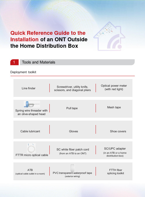
Quick Reference Guide to the Installation of an ONT Outside the Home Distribution Box1Tools and MaterialsDeployment toolkitFTTR micro optical cableSpring wire threader with an olive-shaped headATB(optical cable outlet in a room)PVC transparent waterproof tape(exterior wiring)SC white fiber patch cord(from an ATB to an ONT)Pull tapeCable lubricant Gloves Shoe coversMesh tapeFTTH fiber splicing toolkitSC/UPC adapter(in an ATB or a home distribution box)Line finderScrewdriver, utility knife, scissors, and diagonal pliersOptical power meter (with red light)2Solution SelectionPrinciple: Place the ONT in the TV cabinet in the living room. If the Wi-Fi signal in the bedroom or study is poor, add a router and connect it to the ONT in the living room through a network cable.Site survey and deployment are performed at the same time by one or two technicians upon a home visit.Note :●This mode is preferred when there are at least 3 cables inside the in-wall pipe.●Confirm the cables that can be pulled out with the proprietor. It is recommended that the cables be pulled out in the following priority: telephone cable > network cable > CATV cable.Reusing cables for installation3In-Wall Wiring Operation GuidanceNote :●The wire threader is made of metal. To avoid electric shocks, disconnect the general circuit breaker before the deployment. In addition, wear insulation slip-proof gloves throughout the deployment.●Before the deployment, check whether the RX optical power of the drop cable meets the requirement.●The blue rectangular shell must be removed from the SC connector that is routed through the pipe.1StartDetermine the ATB position at thedeployment point.Is there an in-wall pipe?NoCables ≥ 3Cables ≤ 2.YesUse a spring wire threader with an olive-shaped head toroute the cables.Route the optical cables, and check the optical power change which should bewithin 0.5 dB.Does the customer approve of the exterior wiring solution?NoCan the cables be routed through the pipe?Install a dual-band ONT.Test the Wi-Fi and network port speeds, and test IPTV andvoice services.Obtain confirmation with the customer.EndNoYesYesReplace the old ONT with adual-band one.A cable is found inside the pipe. Use a line finder to confirm the cable, and markboth ends of the pipe.No cable is found inside the pipe.◆User notification◆Label check : labels attached to cables inside the pipe◆Tool identification : line finder (if there are cables inside the pipe)Procedure:1.Verify that the reusable cable or embedded rope is not used and can be pulled.2.Wrap the cable head with the pull tape, and bind them using mesh tape as shown in figure 1.3.Pull out the cable from the other end to deploy the pull tape in the pipe.4.Select a micro optical cable of proper length (20 m or 50 m).5.Warp the optical cable using pull tape (by about 0.5 m) as shown in figure 2.6.Bind the remaining part evenly with mesh tape at 3 or 4 positions as shown in figure 3.7.Pull out the pull tape at an even speed to route the optical cable out of the pipe.8.Connect an ONT. Specifically, test the optical power, connect the optical cable to the optical port of the ONT, and power on and register the ONT.Figure 1Figure 2Figure 3NoteIf obstacles (such as gravel and residual cables) exist, tighten the butterfly nut. If the spring cannot move forward anymore, pull it backwards to pull the obstacles out of the pipe.If you encounter large resistance when pulling the spring backwards, tighten the butterfly nut. Then rotate the handle counterclockwise while pulling the spring backwards.Home distribution boxTV background wallIn-wall pipeSpring wire threader with an olive-shaped head Other cables Pull tape Mesh tape2 Using a spring wire threader with an olive-shaped headProcedure:1. Pass a spring wire threader with an olive-shaped head through the pipe.2. Wrap the head of the wire threader with the pull tape, and bind them using mesh tape.Home distribution boxTV background wall3. Pull out the spring from the other end to deploy the pull tape in the pipe.4. Perform steps 4 to 8 in the method by reusing cables for installation.Bind them using mesh tape.Step 1Hold the handle, loosen the butterfly nut counterclockwise, and pull out part of the spring into the pipe.Step 2Tighten the butterfly nutabout 10 cm away from the weak-current pipe opening.Step 3Step 4Hold the handle and press it down with force. Rotate the handle clockwise with the other hand until the the spring wire threader passes through the right angle.After the spring wire threader passes through the right angle, loosen the butterfly nut. Then continue to pass the spring wire threader through the weak-current pipe.If no pipe or duct is available, implement exterior wiring. It is recommended that you use double-fold waterproof tape and a micro optical cable for neat exterior and good protection.4Exterior Wiring Operation Guidance (Using PVC Transparent Waterproof Tape)Procedure:1.Measure and select a micro optical cable of proper length.2.Plan the route, and mark the installation position and bending reference line.3.Wipe the walls and baseboards to avoid water stain and dust.4.Tear off the release paper from the waterproof tape, stick the optical cable to the waterproof tape, andattach the optical cable and waterproof tape to the walls or baseboards.Layout effect picturesNoteDouble-fold waterproof tape needs to be inspected and maintained regularly. Users can purchase and replace them as desired.A user can also tear the PVC transparent waterproof tape into 2 to 3 folds as desired.Post-deployment cautions After the deployment is complete, take away the rubbish generated during the deployment.Notify users that optical fibers are made of glass, and therefore they cannot be folded for binding.5.Connect an ONT. Specifically, test the optical power, connect the optical cable to the optical port ofthe ONT, and power on and register the ONT.After the optical cable is secured, squeeze the air between the transparent waterproof tape and the wall or baseboard to ensure that they are securely attached.Cable routing around an exposed corner(turning of a flat surface)Cable routing around an internal corner(turning of a flat surface)Cable routing along a baseboardCable routing through a gap between a door and the floor(to pass through obstacles, bumps, and other objects)PVC transparent waterproof tape Specifications: 38 mmx 3.2 m。
广州博德科技(Broadcom)SA-S500设备安装和配置指南说明书
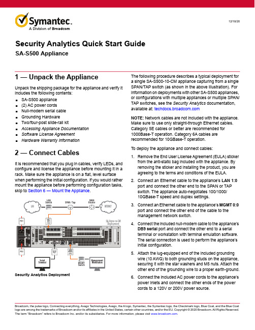
12/18/201 — Unpack the ApplianceU npack the shipping package for the appliance and verify it includes the following contents:⏹SA-S500 appliance ⏹(2) AC power cords⏹Null-modem serial cable ⏹Grounding Hardware⏹Two/four-post slide-rail kit⏹Accessing Appliance Documentation ⏹Software License Agreement ⏹Hardware Warranty Information2 — Connect CablesIt is recommended that you plug in cables, verify LEDs, and configure and license the appliance before mounting it in a rack. Make sure the appliance is on a flat, level surface when performing the initial configuration. If you would rather mount the appliance before performing configuration tasks, skip to Section 6 — Mount the Appliance .The following procedure describes a typical deployment for a single SA-S500-10-CM appliance capturing from a single SPAN/TAP switch (as shown in the above illustration). For information on deployments with other SA-S500 appliances, or configurations with multiple appliances or multiple SPAN/TAP switches, see the Security Analytics documentation, available at: NOTE: Network cables are not included with the appliance. Make sure to use only straight-through Ethernet cables. Category 5E cables or better are recommended for 1000Base-T operation. Category 6A cables are recommended for 10GBase-T operation.To deploy the appliance and connect cables:1.Remove the End User License Agreement (EULA) stickerfrom the anti-static bag included with the appliance. By removing the sticker and installing the product, you are agreeing to the terms and conditions of the EULA.2.Connect an Ethernet cable to the appliance’s LAN 1:0port and connect the other end to the SPAN or TAP switch. The appliance auto-negotiates 100/1000/10GBase-T speed and duplex settings.3.Connect an Ethernet cable to the appliance’s MGMT 0:0port and connect the other end of the cable to the management network switch.4.Connect the included null-modem cable to the appliance’sDB9 serial port and connect the other end to a serial terminal or workstation with terminal emulation software. The serial connection is used to perform the appliance’s initial configuration.5.Attach the lug-equipped end of the included groundingwire (10 AWG) to both grounding studs on the appliance, securing it with the star washers and M5 nuts. Attach the other end of the grounding wire to a proper earth-ground.6.Connect the included AC power cords to the appliance’spower inlets and connect the other ends of the power cords to a 120V or 200V power source.Security Analytics DeploymentSecurity Analytics Quick Start GuideSA-S500 ApplianceSA-S500 Appliance ConfigurationsThe SA-S500 is available in the following appliance configurations with the indicated port enumerations.3 — Power On the Appliance and Verify LEDsTo verify the appliance is operational:1.Confirm the appliance’s power cords are securelyconnected to a power source.2.If the appliance does not automatically power on, pressthe rear soft power switch.NOTE: The state of the appliance’s soft power switch (on or off) is retained when power is removed. This may necessitate pressing the power switch when reapplying power to the appliance.3.As the appliance boots, verify the following:⏹The power LED turns amber.⏹Near the end of the boot cycle, the Power LED alternates between amber and green, indicating an unconfigured state.⏹After the boot cycle has completed, the LCD panel displays information about the appliance, such as model, serial number, and IP address, which can be scrolled with the front-panel arrows.⏹Following the initial configuration and licensing, the Power LED turns green.During operation, the front-panel status LEDs indicate the following states:4 — Perform the Initial ConfigurationYou must have the following network information to initialize the appliance:To perform the initial configuration for the appliance:1.Confirm the appliance’s DB9 serial port is connected toa serial terminal or workstation with terminal software.2.Open a terminal emulation program, such as MicrosoftHyperTerminal®, PuTTY, Tera Term, or ProComm™,and configure it to use the following settings:LED Color DescriptionPower StatusOff Powered off or no power present Amber BootingAmber/green alternating Not yet initializedGreenPowered on and configured System StatusOff Powered off or no power present Green NormalAmber System fault or not yet licensed Amber blinkingCritical fault⏹Appliance IP address ⏹Subnet mask⏹Primary DNS server IP address⏹Link settings (speed and duplex)⏹Default Gateway IP address⏹Admin ID and password⏹Baud rate: 9600 bps ⏹Data bits: 8⏹Parity: none ⏹Stop bits: 1⏹Flow control: none3.Power on the appliance (if it is not already powered on)and log in to the command-line interface (CLI) withdefault credentials: admin | Solera4.Configure the management IP address, netmask, andgateway with the following CLI command, specifying the netmask in dotted-decimal format (255.255.255.0): sudo cfg _ bond _ interface.py -i eth0 -n<IP>/<netmask> -g <gateway>5.When prompted, enter the sudo password: Solera6.Open a browser, navigate to the address just specified,and log in with default credentials: admin | Solera7.When prompted, accept the EULA.8.On the Initial Configuration page, configure the following:hostname; IP address, mask, and default gateway; up to three DNS servers; date, time, and time zone; interface language; and root and admin passwords.NOTE: For more information, see the Initial Settings topic in the Security Analytics documentation, available at: 9.Click Save. If there are no errors, you are prompted tolicense the appliance.5 — License the ApplianceTo license the appliance:1.After completing the initial configuration, you areprompted with the License Details dialog.NOTE: You can also update or change an existinglicense. To do so, select Menu > Settings > About and then click License Details.2.Retrieve your license key from the Broadcom SupportPortal (/security), as instructed in the eFulfillment message from Broadcom.3.If your appliance has Internet access, do the following:⏹Under Retrieve License, enter the License Key andclick Send Request.⏹If applicable, select the license type.⏹The appliance sends the license key and license seedfile to the Symantec license server, which generates the license file (license.tgz) and returns it to the appliance, which automatically reboots.4.If your appliance does not have Internet access, do thefollowing:⏹Click Download DS Seed to download the seed file(dsseed.tgz) to your workstation.⏹On a workstation with Internet access, go to:⏹Type the appliance’s license key, upload dsseed.tgz,and click Submit.⏹If applicable, select the license type and click Submit.⏹Save the license file (license.tgz) to the workstation.⏹Return to the License Details dialog, click Browse, andselect license.tgz. The license is uploaded and theappliance automatically reboots.5.Once the appliance has rebooted, select About>License Details to verify the license.6.Click Download to save an archive copy of the licensefile (license.tgz). Store this file in a secure location that is not on the appliance.6 — Mount the ApplianceThe slide-rail kit included with the appliance allows it to be mounted in a 2- or 4-post equipment rack. The slide-rail kit includes the following parts:NOTE: Installation of the slide rails requires an M4 nut driver or adjustable wrench and a #2 Phillips head screwdriver. If you are working alone, a mechanical lift is also required. NOTE: The following procedure documents how to install the appliance in a 4-post equipment rack. For comprehensive information on rack-mounting the appliance, including other configurations, see the S-Series WebGuide, available at .Rack Warnings and Precautions CAUTION! Before mounting the appliance:⏹Power off the appliance and disconnect all cables.⏹Verify that the weight of the system does not exceed therack’s fully populated weight limit. For more information, refer to the manufacturer’s instructions included withthe rack.⏹For weight stability, load the rack from the bottom up.⏹Read the “Rack Mount Warnings” section of the Safety and Compliance Guide .⏹Take adequate safety and grounding measures to avoid creating an electrical shock hazard and to prevent bodily injury.⏹The appliance is heavy. A two-person lift or mechanical aid is recommended to lift the appliance from the carton and install it in the rack.⏹Do not place objects on the appliance or use it as a work surface. Its mounting hardware does not support additional weight.Attach the Chassis Rails to the ApplianceThe slide-rail assemblies come pre-assembled with the inner chassis rails inside the slide rails. The chassis rails attach to the appliance chassis. The slide rails are installed⏹Fully extend each slide rail by sliding out the chassis rails until they reach the stop.⏹Press the release tab on the chassis rails and slide them all the way out.⏹The chassis rails are symmetrical and can be attached to either side of the chassis.2.Attach the two chassis rails to the appliance:⏹Align each rail to the mounting posts on each side of thechassis.⏹Slide the rail toward the rear of the chassis until the mounting posts snap into place.⏹Secure each inner rail to the appliance with one M4x4L screw.3.Test the slide-rail release latches. They should movesmoothly in both directions with minimal effort.4.Set the appliance aside in a safe location.Install the Slide Rails in a 4-Post RackFor installation in 4-post equipment racks, the slide rails use the Bracket_A and Bracket_C assemblies.To install the slide rails in a 4-post equipment rack:1.Assemble the two slide rails:⏹Loosely attach Bracket_C to the Bracket_A assembly.⏹Secure the brackets with three M4x5L screws, insertedthrough the slot in Bracket_C and screwed into three holes in Bracket_A.⏹Make sure the screws are equidistant from each other so the load will be evenly distributed on the rail. Do notyet fully tighten the screws.⏹The precise attachment location of the side-mounting screws will depend on how far Bracket_C will extend or retract to fit the rack. It may be necessary to removeBracket_C from Bracket_A to determine the proper installation length.2.Install the assembled slide rails in the 4-post rack:⏹Secure Bracket_A to the outside front of the rack with two M6 rack screws. Do not yet fully tighten the screws. You will do so after the appliance is installed in the rack.⏹Extend or retract Bracket_C to align with the outside rear of the rack. Secure the bracket with two M6 rack screws. Do not yet fully tighten the screws. You will do so after the appliance is installed in the rack.⏹Tighten the three side-mounting M4x5L screws, securing Bracket_C to Bracket_A, for each slide rail.Bracket_CBracket_A3.Inspect the installed slide rails:⏹Verify the slide rails are even and installed at the same level in the equipment rack.⏹Make sure the slide rails are free of defect and damage. Make sure there is no debris in the slide rails.⏹Extend and retract the slide rails to verify smooth operation and slide-stop operation.Install the Appliance into the Equipment RackTo install the appliance in the equipment rack and verify slide-rail operation:1.Align the chassis rails attached to the appliance with theslide rails in the rack and slide the appliance half-way into the rack.2.Press the release tabs on the chassis rails to slide theappliance all the way into the rack.3.Slide the appliance out of the rack, far enough to accessthe rack screws. Fully tighten the M6 rack screws securing the slide rails to the rack.4.Verify the slide-rail operation:⏹Press the release tabs on the chassis rails to lock and unlock the appliance in place.⏹Push and pull the appliance to verify smooth movement across the entire slide range.⏹Carefully pull out the appliance all the way to verify the slide-stop functionality.5.Gently push the appliance all the way into the rack andtighten the captive thumbscrews on the rack ears to prevent the appliance from sliding out of the rack.6.Verify the appliance is securely installed in theequipment rack.7.Reconnect the cables as documented in Section 2 —Connect Cables and verify the appliance is functioning as in Section 3 — Power On the Appliance and Verify LEDs .7 — Next Steps⏹If your Security Analytics system includes externalstorage, install the storage arrays per the instructions in the SA-J5300 Quick Start Guide or SA-SM-48T Quick Start Guide , available at: ⏹For additional configuration instructions for SA-S500 appliances—including cabling to storage arrays, and RAID array settings for Capture and Indexing—see the SA-S500 Configuration Guide , available at:Symantec Technical Support⏹For Symantec technical support, case management,licenses, and product downloads, go to /security Security Analytics Help and Documentation⏹For Security Analytics help, in the web UI selectSettings > Help > [language].⏹For Security Analytics software documentation, go to and type “Security” in the search field, then click Security Analytics .Appliance Documentation⏹For Symantec appliance documentation, go to and type “Appliances” in the search field, then click Hardware Appliances .。
Optima5300DV标准安装维护FJW Part2(200809)

page #024
点等离子矩
➢ 点炬前先检查蠕动泵进样和排液,气体压力,通风,切割气压力,冷 却水循环器。
➢ 氩气质量会影响点炬,实验室留存一瓶99.999%高纯氩,在不能点炬 时使用。
page #026
page #027
手动设定气体流量功率和进样量
➢ 气体流量,射频功率和进样量都可以手动设定。设定后按APPLY生效。 ➢ 分析样品时这手动设定气体流量功率和进样量些参数自动转为方法里设定的
参数。 ➢ 当需要在分析时采用与方法设定不同的参数,可以使用Override Method 。
page #021
吹扫气(Purge Gas)
➢ 当使用低于190nm波长分析前, 必须提前用Purge gas(氮气) 吹扫光学室和光学通道。
➢ 吹扫速度分两种,快速8升/分, 常速1.5升/分。
➢ 初次吹扫可以快速吹扫几小时后 转入常速。
➢ 定期吹扫光学室可以保护光学镜 面,避免不良气体或水汽侵蚀。
page #031
光谱仪控制(二)
➢ Align View是校准入射光方向,使入射到狭缝的光强最大。在重装炬 管后校准用。
➢ 校准时要使用1ppm Mn溶液或其他指定溶液,不能在喷纯水条件下 做此项校准。
➢ 在径向和轴向分别做此项校准,仪器将自动保存校准结果。只有在重 新安装炬管后,才需要重新校准。
page #032
光谱仪控制(三)
Wavelength Calibration 用 于➢校。准波长,分UV和VIS两 部分。校准时必须用随机标 准溶液。UV使用N0582152 ,VIS使用N9302946。 当再次选此窗口时,显示上 次校准的时间和结果。 波长校准结果存在计算机里 ,重装软件后必须重做此校 准。
H3cRA5300安装手册

H3cRA5300安装手册
1、进入H3C路由器的管理地址。
192.168.55.1。
输入密码等信息进入页面。
2、先配置管理地址,接口设置,LAN设置。
根据自己的情况配置。
3、配置WAN设置。
配置这个信息之后,所有的电脑都可以通过这台路由器上网。
根据自己的通信连接商,选择对应的连接方式。
4、根据自己局域网的情况,是否设置DHCP,如果简单的一点就开启,下面的客户端自动获取IP。
5、安全专区设置,这里是有关设置那些电脑可以通过这台路由器上网的设置。
禁止客户端更改IP,我们可以绑定,IP及MAC地址。
同时也防ARP病毒。
6、接入控制,就是允许那台电脑可以上网的设置权限。
原理就是通过MAC地址进行的。
允许禁止都是双面的意思,靠大家自己理解了。
7、启用防火墙,开启防攻击。
8、Qos设置,是对局域网的单台电脑进行控制。
9、限制控制,我们可以控制电脑的下载速度,通常限制连接数也是其中的一种方法。
10、高级设置,路由设置,如果公司内部有vpn客户,则就需要设置静态路由了。
设置好后,就重启设备即可。
- 1、下载文档前请自行甄别文档内容的完整性,平台不提供额外的编辑、内容补充、找答案等附加服务。
- 2、"仅部分预览"的文档,不可在线预览部分如存在完整性等问题,可反馈申请退款(可完整预览的文档不适用该条件!)。
- 3、如文档侵犯您的权益,请联系客服反馈,我们会尽快为您处理(人工客服工作时间:9:00-18:30)。
5300安装指导软单缆天线
1N OZZLE安装:
软单缆的安装到6”(150mm)以上的nozzle;通过调整UNZ后,双缆可以安装到2”(50mm)
的nozzle,天线不能接触到Nozzle,Nozzle不允许使用使安装的Nozzle内径大变小的变径。
底部固定要求如下图,重锤的重锤下部螺栓孔为M8*14。
对于非金属罐的单缆(Single Lead)金属法兰安装时,法兰直接大于2”(50mm);金属薄板螺
纹安装,金属薄板直径大于8”(200mm)。
注意天线接地。
固体介质需要考虑应力计算,距离管壁500mm,下端固定,固定要求每米保留1cm的松弛,
防止揽断裂。
2S TILL PIPING安装:
2.1安装要求
2.2C HAMBER 或B RIDLE的制作要求:
连通管内径必须小于导波管内径,焊接处光滑;测量的range不能小于12”(300mm);引压
管内径小于导波管内径;
3定中盘安装如下:
在重锤底部安装定中盘,用螺栓和垫片固定。
距离导波管底25mm。
4天线切割
Flexible Single计算切割长度时要注意插入重锤1.6”(40mm);完成后精确测量剩下的缆长。