W7MG21M32SVT70BNC中文资料
V7操作说明书-3
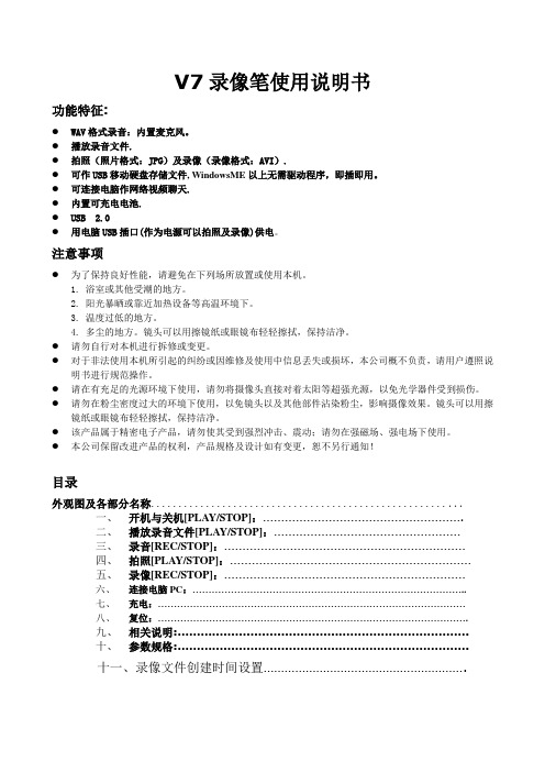
V7录像笔使用说明书功能特征:●WAV格式录音:内置麦克风。
●播放录音文件.●拍照(照片格式:JPG)及录像(录像格式:AVI).●可作USB移动硬盘存储文件, WindowsME以上无需驱动程序,即插即用。
●可连接电脑作网络视频聊天.●内置可充电电池.●USB 2.0●用电脑USB插口(作为电源可以拍照及录像)供电。
注意事项●为了保持良好性能,请避免在下列场所放置或使用本机。
1. 浴室或其他受潮的地方。
2. 阳光暴晒或靠近加热设备等高温环境下。
3. 温度过低的地方。
4. 多尘的地方。
镜头可以用擦镜纸或眼镜布轻轻擦拭,保持洁净。
●请勿自行对本机进行拆修或变更。
●对于非法使用本机所引起的纠纷或因维修及使用中信息丢失或损坏,本公司概不负责,请用户遵照说明书进行规范操作。
●请在有充足的光源环境下使用,请勿将摄像头直接对着太阳等超强光源,以免光学器件受到损伤。
●请勿在粉尘密度过大的环境下使用,以免镜头以及其他部件沾染粉尘,影响摄像效果。
镜头可以用擦镜纸或眼镜布轻轻擦拭,保持洁净。
●该产品属于精密电子产品,请勿使其受到强烈冲击、震动;请勿在强磁场、强电场下使用。
●本公司保留改进产品的权利,产品规格及设计如有变更,恕不另行通知!目录外观图及各部分名称.........................................................一、开机与关机[PLAY/STOP]:……………………………………………….二、播放录音文件[PLAY/STOP]:……………………………………………三、录音[REC/STOP]:…………………………………………………………四、拍照[PLAY/STOP]:…………………………………………………………五、录像[REC/STOP]:…………………………………………………………六、连接电脑PC:…………………………………………………………………………..七、充电:……………………………………………………………………………………八、复位:…………………………………………………………………………………….九、相关说明:………………………………………………………………….十、参数规格:………………………………………………………………….十一、录像文件创建时间设置………………………………………………….外观图及各部件名称1、MODE 模式开关2、LED 双色工作指示灯3、PLAY/STOP 播放/开关机/拍照4、REC/STOP 录音/录像5、RESET 复位键6、USB USB插头7、EARPHONE 耳机插孔按键及操作说明:一、开机与关机[PLAY/STOP]:开机:长按[PLAY/STOP]键约4秒开机,开机后“LED红灯”长亮进入待机状态。
Moog Inc. Series 72K 电液伺服阀手册说明书
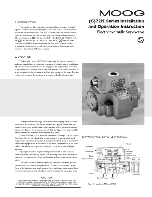
�(G)72K Series Installation ELECTROHYDRAULIC VALVE CUT-AWAYCoilArmature MagnetFlexure Tube Inlet OrificePolepiece ConnectorFilterFeedback WireSpoolFigure 1 Moog Series 72K and (G)72KSupply PressureBTankANozzle3. ELECTRICAL INFORMATION AND INTRINSICALLY SAFE CIRCUIT SAFETY PARAMETERSa. A wide choice of coils is available for a variety of rated currentrequirements. The torque motor coil leads are attached to the connector so external connections can provide series, parallel or single coiloperation. The valves are equipped either with an MS type connector or with pigtail leads for electrical wiring. Refer to installation drawings of the specific model for details. Servovalve coils should be driven with current to provide consistency throughout the temperature range.b. The (G)72K valves are approved for intrinsically safe protection per EN60079-11. The approved safety parameters are listed in the following table for all the coils used by (G)72K series. Coil number is marked on thevalve nameplate.Coil Configuration Marking U i (MAX) I i (MAX) G4220-031 (single, series, parallel) Ex ia IIB T4 12 V 120 mAG4220-051/098 (single, series, parallel) Ex ia IIB T4 12 V 240 mAG4221-001 G4220-042 (single) Ex ia IIC T4 16 V 160 mA G4221-001 G4220-042 (single) Ex ia IIC T4 24.4 V 85 mAG4220-031 (single, parallel) Ex ia IIC T4 30 V 26 mAG4220-031 (series) Ex ia IIC T4 30 V 18 mAG4220-051/098 (single, parallel) Ex ia IIC T4 30 V 19 mA G4220-051/098 (series) Ex ia IIC T4 30 V 12.7 mAG4220-042 (single) Ex ia IIC T4 30 V 37 mAG4220-042 (parallel) Ex ia IIC T4 30 V 20 mAG4220-042 (series) Ex ia IIC T4 30 V 10 mAG4221-001 (single) Ex ia IIC T4 30 V 28 mAc. The (G)72K valves are approved for non-incendive operation for supplycurrent not to exceed 50 mA dc.d. When making electric connections to the valve, appropriate measures mustbe taken to ensure that locally different earth potential do not result inexcessive ground currents. When barriers are required for the hazardous location, hazardous area (field) wiring must meet the requirements ofthe barrier manufacturer. All barriers must be mounted and installed incompliance with the barrier manufacturer’s requirements. Twisted pairs of 18-20 gage wire are recommended. If shielded wire is used, connect shield wire to earth ground only at the barrier strip.4. SPECIAL CONDITIONS FOR SAFE USEBecause the enclosure of the apparatus is made of aluminum, if it is mounted in an area where the use of category 1 G apparatus is required, it must be installed such that even in the event of rare incidents, ignition sources due to impact and friction sparks are excluded.When the electrohydraulic servovalve is used in an application for type of explosion protection intrinsic safety “i”, the appropriate box on the data label must be scored. When the electrohydraulic servovalve is used in an application for type of explosion protection “n”, the appropriate box on the data label must be scored.After use in an application for type of explosion protection “n”, the servovalve cannot abe safely used in a intrinsically safe application.The screwed cable connector may only be disconnected when the circuit is de-energized or when the location is known to be non-hazardous.When used at an ambient temperature ≥70°C, heat resistant cable must be used with a continuous operating temperature in accordance with the application.5. HYDRAULIC SYSTEM PREPARATIONTo prolong servovalve operational life and to reduce hydraulic system maintenance, it is recommended that the hydraulic fluid be kept at a cleanliness level of ISO DIS 4406 Code 16/13 maximum, 14/11 recommended. The most effective filtration scheme incorporates the use of a kidney loop or “off-line” filtration as one of the major filtration components. The filter for the “off-line” filtration scheme should be a ß3≥75 filter for maximum effectiveness.Upon system startup and prior to mounting the servovalve, the entire hydraulic system should be purged of built-in contaminating particles by an adequate flushing. The servovalve should be replaced by a flushing manifold and the hydraulic circuit powered up under conditions of fluid temperature and fluid velocity reasonably simulating normal operating conditions. New system filters are installed during the flushing process whenever the pressure drop across the filter element becomes excessive. The flushing processes should turn over the fluid in the reservoir between fifty to one hundred times.To maintain a clean hydraulic system, the filters must be replaced ona periodic basis. It is best to monitor the pressure drop across the filter assembly and replace the filter element when the pressure drop becomes excessive. In addition to other filters that are installed in the hydraulic circuit, it is recommended that a large capacity, low pressure ß3≥75 filter be installedin the return line. This filter will increase the interval between filter element replacements and greatly reduce the system contamination level.6. INSTALLATIONThe Moog (G)72K series industrial servovalve may be mounted in any position, provided the servovalve pressure, control, and tank ports match respective manifold ports. The mounting pattern and port location of the servovalve is shown on Figure 4. The servovalve should be mounted with 3/8-16 x 2.00 inch long, socket head cap screws. Apply a light film of oil to the screw threads and torque to 175 inch-pounds. Wire mating connector for desired coil configuration and polarity. Thread connector to valve.7. MECHANICAL NULL ADJUSTMENTIt is often desirable to adjust the flow null of a servovalve independent of other system parameters. The “mechanical null adjustment” on the Moog (G)72K Series servovalve allows at least ±20% adjustment of flow null. The “mechanical null adjustor” is an eccentric bushing retainer pin, located above the tank port designation on the valve body (see Figure 2) which, when rotated, provides control of the bushing position. Mechanical feedback elements position the spool relative to the valve body for a given input signal. Therefore, a movement of the bushing relative to the body changes the flow null. Mechanical Adjustment ProcedureUsing a 3/8 inch offset box wrench, loosen the self-locking fitting until thenull adjustor pin can be rotated. (This should usually be less than 1/2 turn). DO NOT remove self-locking fitting. Insert a 3/32 inch Allen wrench in null adjustor pin. Use the 3/32 Allen wrench to rotate the mechanical null adjustor pin to obtain desired flow null. Torque self-locking fitting to 57 inch lbs. Note:Clockwise rotation of null adjustor pin produces flow from port P to port B.Tools and Equipmenta. Blade screwdriverb. Allen wrench set (3/32, 7/64, 3/8, 3/16)c. No. 2-56 NC by 11/2 inch screwd. Torque wrenchese.3/8 inch offset box wrenchf. TweezersFigure 2Mechanical NullAdjustment10. FIELD REPLACEABLE FILTER ASSEMBLY REPLACEMENTa.Remove four socket head cap screws and lockwashers on filter cover using a 3/16 inch Allen wrench. Remove filter cover plate. Use to pull filter plug out.b. Remove o-rings and old filter from filter plug.c. Inspect filter for foreign material and discard.d. Install o-rings on filter plug and inside new filter.e.Install filter, filter plug and cover plate. Torque screws to 85 inch-pounds.11. FUNCTIONAL CHECKOUT AND CENTERINGa. Install servovalve on hydraulic system or test fixture, but do not connect electrical lead.b. Apply required system pressure to servovalve and visually examine for evidence of external leakage. If leakage is present and cannot be rectified by replacing o-rings, remove the discrepant component and return for repair or replacement.Note: If the system components are drifting or hardover, adjust the mechanical null of the servovalve.c. Connect electrical lead to servovalve and check phasing in accordancewith system requirements.Figure 3Filter Tube Inlet Orifice AssemblyFilter PlugFieldReplaceable FilterFilter HousingO-Rings8. GENERAL SERVICING RECOMMENDATIONSa. Disconnect electrical lead to servovalve.b. Relieve hydraulic system of residual pressure.(G)72K SERIES INSTALLATION AND OPERATION INSTRUCTIONCDS6754 RevD 500-448 0718Moog Inc., East Aurora, NY 14052-0018 Telephone: 716/652-2000Fax: 716/687-7910Toll Free: 1-800-272-MOOG TYPICAL WIRING SCHEMATICThe products described herein are subject to change at any time without notice, including, but not limited to, product features, specifications, and designs.3。
冠捷2271说明书
• 机壳后部和底部的槽和开口用于通风目的。为确保监视器可靠运行而不会过热,切勿阻塞或覆盖
这些开口。不要将监视器放置在床、沙发、地毯或类似的表面上。不要将监视器放置在暖气片或 热调节器上面或附近位置。不要将监视器放置在书柜或橱柜中,除非通风良好。
《废弃电器电子产品回收处理管理条例》提示性说明 ..............................4 标准配置......................................................................................................... 5 安装支架底座................................................................................................. 6 调整视角......................................................................................................... 6 连接电缆......................................................................................................... 7 安装墙壁装配架............................................................................................. 8 设置最佳分辨率............................................................................................. 9 外部控制....................................................................................................... 10 MENU 菜单说明.......................................................................................... 11 快捷键使用说明........................................................................................... 11 菜单图标说明............................................................................................... 12 LED 指示灯.................................................................................................. 16 I-MENU 软件............................................................................................... 16 安装驱动程序............................................................................................... 17 常见问题解答............................................................................................... 19 规格............................................................................................................... 20
西门子7KM2112资料(说明书)

Sinusoidal or distorted 45 65 RMS 185.8 P
1 TRMS
65 45 AC/DC CATIII
8 6 10
IP65 IP20 II
100
5
Installation in stationary control panels in closed rooms 10
Yes Yes Yes Yes Yes Yes
s s
kbit/s kbit/s
V V V
mA mA
LCD, graphical, monochrome 4 white ger, en, fr, spa, ita, por, tur, chi
128 96
0.33 1 Yes
MODBUS TCP SEAbus TCP / MODBUS TCP (switchable)
10 000 10 000
Acc. to IEC62053-22 and IEC62053-23
Class 2 according to IEC61557-12 and/or IEC6205323 +/- 0,5 % +/- 0,5 % +/- 0,3 % +/- 0,2 % Cl. 0.5 acc. to... IEC62053-22
Measuring category / for supply voltage
Apparent power consumption
● with expansion module / maximum
V·A
● without expansion module / typical
V·A
Relative symmetrical tolerance / of the supply voltage %
韩国优技因特UGINT钻攻中心

◆ 生产品 : 汽车、摩托车配件及小型发电机配件, 割草机配件等
09
PT 400S 620×390 X:520 24,000 Y : 400 [20,000] Z : 350{480}
2.1sec [2.3sec] {2.0sec}
14EA [20EA]
{20EA} 150kgs {24EA} [200kgs]
◆ 生产品 : IT相关部品,汽车配件及汽车美容产品等
UT360D2-650×400 X:520 12,000 Y : 360 [15,000] Z : 350{480} [24,000]
Before Clamping
After Clamping
$MBNQJOH
/PO$POUBDU
$POUBDU
适用双面约束主轴 (PT400S 标准)
通过采用同时接触主轴截面和锥度截面的双面约束的专用主轴 (BBT #30), 加强了稳固性能, 减少了振动, 可以进行高精度的高速切削。 通过增加基准直径,提高刚性及ATC重复精密度,而且通过避免高 速旋转时的Z轴的位移,增加了工具的寿命。
UT420 / UM450
14EA [20EA] {20, 24EA} BT30 [BT40] 3kg {2.8kg} 随机 1.2sec {1.1sec}
2.1sec {2.0sec}
PT400S
14EA [20EA] {20, 24EA} BBT30 3kg 随机
1.1sec {1.1sec} 2.1sec {2.0sec}
{20EA} 150kgs {24EA} [200kgs]
以更精巧的设计再次诞生的小型加工中心 - 最畅销产品
规格
CNC规格 工作台尺寸 (mm) 主轴功率 (kW) 主轴转速 (r/min) 最大行驶距离 (X/Y/Z) (mm) 快速进给速度 (X/Y/Z) (m/min) 刀库容量
WFM7120技术资料

视频监视 - 3G(3 Gb/s) - DL(双链路) - HD(高清晰度 SDI) - SD(标准清晰度 SDI) - CPS(复合模拟)
音频监视 - AD(AES、嵌入音频和模拟音频) - DDE(杜比数字和杜比 E 音频)
测量和分析 - JIT(3 Gb/s 抖动测量) - EYE、PHY(物理层分析) - DAT(数据分析) - SIM(同时输入监视) - AVD(A/V 延时测量)
WFM7020
WFM7020 为模拟、数字、高帧频数字视频和多种音频格式的 基本监视提供了一种理想的解决方案。
各种监视显示模式,例如波形、矢量、色域、定时、数据分析、 状态报告和音频监视等功能均可用于监视 3 Gb/s 和其它格式 信号。
泰克公司的独有选件 JIT 为 WFM7120 提供了 3G 视频格式的 抖动测量功能,此外还包括基本测试循环信号发生器(含彩条和 病理测试信号),这样,在验证3G信号格式时就更加方便快捷。
WFM6120
WFM6120 为 SD-SDI 和模拟复合视频格式提供了高性能的监 视和测量功能。
WFM6120 的 AD 音频选件可用于监视模拟音频和数字嵌入音 频或 AES/EBU 音频。
其它可用的选件包括眼图 / 抖动(EYE 或 PHY)、视频数据分析 (DAT)和 AV 延迟测量(AVD)等。
选件 DDE 能够显示 VANC 杜比元数据。SIM(同时输入)选件使 仪器能够同时显示两路输入信号,如同一台二合一的仪器。
6WMM7 系列主機板 中文安裝手冊
6WMM7 ¨t¦C¥D¾÷ªO¤¤¤å¦w¸Ë¤â¥U1. 6WMM7¨t¦C¥D¾÷ªO¥]§t6WMM7(¨Ï¥Î82810-DC100´¹¤ù²Õ),6WMM7-1 (¨Ï¥Î82810 ´¹¤ù²Õ) , 6WMM7-E (¨Ï¥Î82810E´¹¤ù²Õ).2. ¤ä´©Dual BIOS ¥\¯à (¿ïÁÊ°t³Æ).3. ¤ä´©ISA Bus Slot (¿ïÁÊ°t³Æ).4. ¤ä´©YAMAHA YMF744 -µ®Ä´¹¤ù (¿ïÁÊ°t³Æ).5. ¤ä´©Suspend to RAM ¥\¯à.6. ¤ä´©AMR ¥\¯à.7. PS/2·Æ¹«¶}¾÷¥\¯à:±z¥i¥H³z¹L«ö¨â¤U§AªºPS/2·Æ¹«¥kÁä©Î¥ªÁä¨Ó¶}±Ò§Aªº¨t²Î(½Ð¥ý¦b BIOS¤¤³]©w PS/2·Æ¹«¶}¾÷¥\¯à¦Ü¶}±Òª¬ºA) ¡C8. Áä½L¶}¾÷¥\¯à: ¦pªG±z¨Ï¥ÎªºATX¹q·½¨ÑÀ³¾¹¦³¤ä´©300²@¦w°ö¥H¤W5V Stand-By ¹q¬y(µøÁä½Lªº³W®æ¦Ó©w)¡A±z´N¥i¥H¨Ï¥ÎÁä½L¶}¾÷¡AÁä¤J¦Û³]ªº±K½X¨Ó¶}±Ò¹q¸£(½Ð¥ý³]©w¥D¾÷ªO¤WÁä½L¶}¾÷±µ¸}¤ÎBIOS¤¤ªºÁä½L¶}¾÷±K½X,¨Ã¦bÁä¤J±K½X«á½Ð«öENTER)(¿ïÁÊ°t³Æ)¡C9. ¤ä´©3¶¥¬qACPI «ü¥Ü¿O¡C10. ¤ä´©¥~±µ¼Æ¾Ú¾÷¶}¾÷¥\¯à(COM A,COM B),¤º±µ¦¡¼Æ¾Ú¾÷¶}¾÷¥\¯à¡C11. ¤ä´©ºô¸ô»·ºÝ¶}¾÷¥\¯à(ATX¹q·½¨ÑÀ³¾¹¦Ü¤Ö¤ä´©720²@¦w°ö¥H¤Wªº5V Stand-By¹q¬y) ¡C12. ¤ä´© TV/DFP(Digital Flat Panel)¥\¯à by TV/DFP daughter card(¿ïÁÊ°t³Æ).13. PCB 2.0¤Î¤§«áª©¥»¦³¤ä´©Intel Pentium®!!! L2 256KB Socket 370¨t¦C³B²z¾¹.INTEL ®Celeron TM/Pentium®!!! Socket 370 ³B²z¾¹¥D¾÷ªOREV. 2.0 Third EditionR-20-03-000331C6WMM7 ¨t¦C¥D¾÷ªO¥»¤â¥U©Ò¦³´£¤Î¤§°Ó¼Ð»P¦WºÙ¬ÒÄݸӤ½¥q©Ò¦³¡C ¥»¤â¥U-Y¦³¥ô¦ó¤º®e-קï¡A®¤¤£¥t¦æ³qª¾¡C2000¦~ 3¤ë31¤é ¥x¥_¡A¥xÆW1I. §Ö³t¦w¸Ë«ü«nCPU ³t«×³]©w¨t²Î³t«×¥iÂÇ¥ÑJP1&JP33½Õ¾ã66,100,133MHz, CPU ªº-¿ÀW¥i¦b BIOS¤¤½Õ¾ã. ³]©w¨t²Î¥~ÀW³t«×.¹Ï 2: 82810E chipset CPU ³t«×³]©w26WMM7 ¨t¦C¥D¾÷ªO 3M ½Ðª`·N¥D¾÷ªO¤W Jumper¥~ÀWªº³]©w¤ÎBIOS¤º-¿ÀW½Õ¾ã¡A»Ý-n©M C PUªº-¿ÀW ¤Î¥~ÀW¬Û²Å¦X¡A§_«h©ö³y¦¨¨t²Î·í¾÷¡CM½Ð¨Ì¾Ú±z CPU ªº³W®æ¨Ó³]©w CPU ªºÀW²v ,§Ú-̤£«Øij±z±N¨t²Î³t«×³]©w¶W¹L µwÅ餧¼Ð·Ç½d³ò,¦]¬°³o¨Ç³W®æ¹ï©ó©PÃä³]³Æ¦Ó¨¥¨Ã¤£ºâ¬O²Å¦X¼Ð·Ç³W®æ¡C ¡¹Note:·í¥D¾÷ª©¨Ï¥Î82810E´¹¤ù²Õ®É,JP33¤~¦³§@¥Î.JP17~JP20 (¿ïÁÊ°t³Æ) (See ¹Ï-2)(ICS 9248-73)CPUSDRAM PCI JP20 JP19 JP18 JP17 AUTO100 33 open open 2-3 2-3 150150 37.5 1-2 2-3 2-3 1-2 140140 35 2-3 2-3 2-3 1-2 133.3133.3 44.43 2-3 1-2 1-2 2-3 133.3133.3 33.32 1-2 1-2 1-2 2-3 124124 41.33 1-2 2-3 1-2 2-3 120120 40 2-3 2-3 1-2 2-3 114.99114.99 38.33 2-3 1-2 2-3 1-2 105105 35 2-3 1-2 2-3 2-3 100.9100.9 33.63 1-2 2-3 2-3 2-3 100.23100.23 33.41 2-3 2-3 2-3 2-3 9595 31.67 1-2 1-2 1-2 1-2 9090 30 2-3 1-2 1-2 1-2 83.31124.96 41.65 1-2 2-3 1-2 1-2 75112.5 37.5 2-3 2-3 1-2 1-2 70105 35 1-2 1-2 2-3 1-2 66.89 100.33 33.44 1-2 1-2 2-3 2-3JP17/ JP18 / JP19 / JP20 (¿ïÁÊ°t³Æ) :46WMM7 ¨t¦C¥D¾÷ªOII. Jumper³]©wªº§Ö³t¦w¸Ë«ü«n:GN : ¬Ù¹q¼Ò¦¡´«¶}Ãö(Green Function Switch)5HD : µwºÐ¦s¨ú«ü¥Ü¿O±µ¸}(IDE Hard Disk Active LED)66WMM7 ¨t¦C¥D¾÷ªO 7J16 : ¤º«Ø¸Á»ï¾¹¶}Ãö±µ¸} (¿ïÁÊ°t³Æ)PW LED : ¤T¶¥¬qACPI «ü¥Ü¿O³s±µ¸}86WMM7 ¨t¦C¥D¾÷ªOIR / CIR : ¬õ¥~½u´¡®y (Infrared Connector)9USB : USB³W®æ´¡®y106WMM7 ¨t¦C¥D¾÷ªOPWR FAN : ¹q·½´²¼ö-·®°¹q·½±µ¸}11IDE1 : ²Ä¤@²Õ IDE´¡®y126WMM7 ¨t¦C¥D¾÷ªOFLOPPY: ³nºÐ´¡®y13COM B / LPT Port : COM B ¦ê¦C°ð´¡®y/ LPT ¨Ã¦C°ð´¡®y146WMM7 ¨t¦C¥D¾÷ªOCOM A : COM A ¦ê¦C°ð´¡®y15JP13 : PS/2Áä½L¶}¾÷¥\¯à±µ¸}(Keyboard Power On Selection) (¿ïÁÊ°t³Æ)166WMM7 ¨t¦C¥D¾÷ªOJ9 : ¥úºÐ¾÷-µ·½½u±µ¸}(CD Audio Line In)17JP16 TEL : (¤º±µ¼Æ¾Ú¾÷-µ·½±µ¸})The connector is for Modem with internal voice connector.186WMM7 ¨t¦C¥D¾÷ªO19J6 : ¤º«Ø¼Æ¾Ú¾÷³ê¿ô¥\¯à±µ¸}(RING PWR ON)JP9 : STR LED ±µ¸}206WMM7 ¨t¦C¥D¾÷ªOJP2 : Top Block Lock21TV/DFP : TV-Out / Digital Flat Panel Daughter card connector.226WMM7 ¨t¦C¥D¾÷ªOJP24 : «e-±ªO USB³W®æ´¡®y(¿ïÁÊ°t³Æ)23JP4 : Timeout Reboot ¥\¯à246WMM7 ¨t¦C¥D¾÷ªOYMF 744 : YAHAHA YMF744 (¿ïÁÊ°t³Æ).25JP31 : AMR¿ï¾Ü±µ¸} (¿ïÁÊ°t³Æ)266WMM7 ¨t¦C¥D¾÷ªO27III. ¦p¦ó³]©w¤~¯à±o¨ì³Ì°ª®Ä¯q¦pªG±z§Æ±æÀò±o³Ì°ªªº¨t²Î®Ä¯q¡A½Ð«ö·Ó¥H¤U«Øij-Ȩӳ]©w¡C*·í¥D¾÷ªO¨Ï¥Î82810E´¹¤ù²Õ®É, ” Local Memory Frequency 133Mhz” ¤~¯à¨Ï¥Î.CMOS Setup Utility -Copyright( C ) 1984-1999 Award SoftwareAdvanced Chipset Features¥H¤U¬O6WMM7ªº´ú¸Õ¼Æ¾Ú¡A°ò¥»¤W³o¨Ç´ú¸Õ¼Æ-ȶȨѰѦҡA¦]¬°¤£¦Pªº³n¡Bµw Åé°t³Æ³£·|¼vÅT´ú¸Õµ²ªG¡A©Ò¥H§Ú-̵Lªk«OÃҨϥΪ̦ۦæ´ú¸Õªº¼Æ¾Ú·|»P¤U¦C¤½§G¼Æ-ȧ¹¥þ§k¦X¡C• CPU INTEL®Celeron TM 533MHz Socket 370 ³B²z¾¹• °O¾ÐÅé (128 x 1) MB SDRAM (Winbond 902WB W986408BH-8H))• §Ö¨ú°O¾ÐÅéCPU¤º«Ø128 KB§Ö¨ú°O¾ÐÅé• Åã¥Ü¤¶-±¥d ¤º«Ø-^¥Nº¸Corporation 810 Graphics Controller Hub)(4MB SDRAM)• Àx¦s¸Ë¸m¤º«Ø IDE ³s±µ°ð(µwºÐ IBM DTTA-371800)• §@·~¨t²ÎWindows NT™ 4.0 SPK5• ÅX°Êµ{¦¡ Åã¥Ü¥dÅX°Êµ{¦¡¨Ï¥Î1024 x 768 x 16bit x 75Hz ¸ÑªR«×Processor Intel® Celeron TM (Socket370)533MHz (66x8)Winbench99CPU mark9939.4FPU Winmark 99 2860 Business Disk Winmark 99 3450 Hi-End Disk Winmark 99 5470 Business Graphics Winmark 99 142 Hi-End Graphics Winmark 99 367 Winstone99Business Winstone9928.2Hi-End Winstone99 22.5286WMM7 ¨t¦C¥D¾÷ªO 29IV. ¦w¸Ë Suspend To RAM ¥\¯àA.1 STR ¥\¯à²¤¶STR¬O¤@ºØWindows 98 ACPI¤Uªº¼È°±¼Ò¦¡¥\¯à¡C·í«ì´_STR¼È°±¼Ò¦¡,¨t²Î¯à°÷¦b´X¬íÄÁ¤§¤º¦^´_¨ì¶i STR¤§«eªºª¬ºA,³oª¬ºA¬O¦b¨t²Î¶i¤J¼È°±¼Ò¦¡¤§«e´N¤w¸g³Q¦s¦b°O¾ÐÅ餺,·í¦b STR¼È°±¼Ò¦¡®É,¨t²Î±N·|¨Ï¥Î¤Ö¶qªº¯à·½¥hºû«ùSTR¥\¯à-«-nªº¸ê®Æ,¨Ã¤ä´©¦UºØ¤£¦P¼Ò¦¡ªº³ê¿ô¥\¯à¡C A.2 STR ¥\¯à¦w ¸Ë½Ð¨Ì·Ó¤U¦C¨BÆJ¨Ó§¹¦¨STR¦w¸ËSETP 1:¨Ï¥ÎWindows 98¥úºÐ¤ù¦w¸ËA. ±N Windows 98¥úºÐ¤ù©ñ¤J¥úºÐ¾÷¤¤, ¿ï¾Ü¶}©l , ¨Ã°õ¦æ¡CB. ¨ÌWindow³W©wÁä¤J “D:\setup /p j”, «ö¤U enter©ÎÂùÀ»·Æ¹«¨â¤U ¡C ¡y©Ò¦³¦b12/01/99¤§«áªºBIOSª©¥»,¬Ò¬°Windows98 ACPICompatible BIOS.¦¹®É¥u-nÁä¤J"D:\Setup", «K·|¦Û°Ê¦w¸Ë¨t²Î¬°ACPI mode.¡zC. ·í¦w¸Ë§¹¦¨«á,±q¥úºÐ¾÷¤¤²¾°£¥úºÐ¤ù,¨Ã-«·s±Ò°Ê±zªº¨t²Î¡C(§Ú-Ì°²³]¥úºÐ¾÷ªº¥N¸¹¬°D:)Suspend To RAM ¥\¯à 30STEP 2:·í¨Ï¥ÎSTR¥\¯à¤§«e ,±z»Ý-n³]©w¥D¾÷ªO¤WªºJ P11µu¸ô,¦p¤U¹Ï©Ò¥Ü:6WMM7 ¨t¦C¥D¾÷ªOA.3 ¦p¦óÅý±zªº¨t²Î¶i¤J STR¼Ò¦¡?¦³¨âºØ¤è¦¡¨Ó§¹¦¨:1.¿ï¾Ü”Ãö³¬Windows”¤¤ªº” ¼È°±” ¿ï¶µA. ¦bWindows98¥\¯à¦C¿ï¾Ü”¶}©l”¨Ã¿ï”Ãö¾÷”B. ¿ï¾Ü”¼È°±”¨Ã«ö¤U”½T©w”¡C31Suspend To RAM¥\¯à2. ©w¸q¨t²Î¶}¾÷®É¬O¦bSTR¼Ò¦¡¤¤:A. ¥Î·Æ¹«ÂùÀ»”§Úªº¹q¸£”¤¤ªº”±±¨î¥x” ¡CB. ¥Î·Æ¹«ÂùÀ»”¹q·½ºÞ²z”¿ï¶µ¡C326WMM7 ¨t¦C¥D¾÷ªO 33C. ¿ï¾Ü”¶i¶¥”¨Ã¿ï”µ¥-ԨϥΔ¼Ò¦¡.STEP 4 :¦b§¹¦¨³]©w«á-«·s±Ò°Ê§Aªº¨t²Î.·í±z·Q-n¶i¤J STR¬Ù¹q¼Ò¦¡®É,¥u-n«ö¤U ”¹q·½¶}Ãö”«ö¶s§Y¥i¡CA.4 ¦p¦ó«ì´_¨ìSTR¬Ù¹q¼Ò¦¡?¦³7ºØ¤è¦¡¥i ¥H ”³ê¿ô”¨t²Î:1. «ö¤U ”¹q·½¶}Ãö”«ö¶s¡C2. ¨Ï¥Î”PS/2Áä½L¶}¾÷”¥\¯à¡C3. ¨Ï¥Î”PS/2·Æ¹«¶}¾÷”¥\¯à¡C4. ¨Ï¥Î”©w®É¶}¾÷”¥\¯à¡C5. ¨Ï¥Î”¼Æ¾Ú¾÷¶}¾÷”¥\¯à¡C6. ¨Ï¥Î”ºô¸ô¥d¶}¾÷”¥\¯à¡C7. ¨Ï¥Î”USB³]³Æ³ê¿ô”¥\¯à¡CSuspend To RAM ¥\¯à 34A.5 ª`·N¨Æ¶µ:1.¬°¤F-n¨Ï¥Î¥¿½TªºSTR¥\¯à,¤@¨ÇµwÅé¤Î³nÅ骺»Ý¨D¬O¥²¶·²Å¦Xªº:A. ±zªºATX ¹q·½¨ÑÀ³¾¹¥²¶·-n¬O ATX 2.01ªº³W®æ(¨ÑÀ³¶W¹L 720²@¦w°ö5V Stand-By¹q¬y )C. SDRAM ¥²¶·¬O²Å¦X PC-100³W®æ.2. JP9 ¬O STR «ü¥Ü¿Oªº±µ¸}.·í¨t²Î¶i¤J STR ¬Ù¹q¼Ò¦¡®É,STR «ü¥Ü¿O±N·|«G°_.6WMM7 ¨t¦C¥D¾÷ªO 35V. ÂùBIOS(Dual BIOS)¥\¯à¤¶²Ð (¿ïÁÊ°t³Æ)A. ¦ó¿×ÂùBIOS (Dual BIOS)?¥D¾÷ªO¤W¦³¨âÁûBIOS,¤À§O¬°”¥D-n BIOS(Main BIOS)”¤Î”³Æ¥÷BIOS (Backup BIOS)”¡C¦b¤@¯ëªº¥¿±`ª¬ºA¤U ,¨t²Î¬O¥Ñ¥D-n BIOS¦b¹B§@,-Y ±zªº¨t²Î¥D-n BIOS ·lÃa®É,«h³Æ¥÷BIOS ±N·|±µºÞ¶}¾÷ªº°Ê§@¨Ã¦Û°Ê-×´_¥D-n BIOS,¦¹®É±zªº¨t²Î´N¥i¥H¹³¥H©¹¤@¼Ë¥¿±`ªº¤u§@¡CB. ÂùBIOS¥\¯à¤Î¨Ï¥Î¤èªka. ¶}¾÷µe-±BIOS ¥\¯à¤¶²Ðb. Dual BIOS µ{¦¡µe-±Dual BIOS Utility V6.60.g.01K(C) 1999, Gigabyte Technology Co., LTD.Wide Range Protection :DisabledHalt On BIOS Defects :DisabledAuto Recovery :EnabledBoot From :Main BIOSBIOS Recovery :Main to BackupF3: Load Default F5:Start BIOS RecoveryF7: Save And Restart F9:Exit Without SavingUse <Space> key to toggle setupC. Dual BIOS µ{¦¡¿ï¶µ»¡©úWide Range Protection: Disabled(¹w³]-È), Enabledª¬ªp1:·í¥D-nBIOS¦b¹q·½¶}±Ò¤§«á,§@·~¨t²Î¸ü¤J«e,-Y¦³Failureª¬ªp(¨Ò¦p:Update ESCD Failure, Checksum Error©ÎReset), ¦¹®ÉWide Range Protection-Y³]¬°Enabled,·|¦Û°Ê¤Á´«¨ì³Æ¥÷BIOS¨Ó§¹¦¨¶}¾÷°Ê§@¡Cª¬ªp2:©PÃä¥d(¨Ò¦p:SCSI¥d,ºô¸ô¥d…)¤W-Y¦³R OM BIOS,¨Ã¶i¨äBIOS¤º°µ¥ô¦óªº³]©w, ³]©w§¹²¦«á,¦¹®É-Y¥Ñ©PÃä¥dªºROM BIOSµo¥X°T¸¹-n¨D¨t²Î-«¶}¾÷,«h¤£·|¥Ñ³Æ¥÷BIOS¨Ó¶}¾÷¡C¦ý-Y¬O¨Ï¥ÎªÌ¦Û¦æ«ö¹q¸£¾÷´ß-±ª©-«¶}¾÷«ö¶s,«h·|¥Ñ³Æ¥÷BIOS¨Ó¶}¾÷¡C Halt On BIOS Defects : Disabled(¹w³]-È), Enabled·íHalt On BIOS Defects³]¬°Enabled®É,-Y CHECKSUM ERROR©ÎMAIN BIOS IS WIDE RANGE PROTECTION ERROR, «h¶}¾÷®É·|¥X²{¥H¤U°T®§;¨Ã¨Ï¨t²Î¼È°±,µ¥«Ý¨Ï¥ÎªÌ«öÁä°µ¶i¤@¨B³B²z:-Y Auto Recovery :Disabled·|Åã¥Ü<or the other key to continue.>-Y Auto Recovery :Enabled·|Åã¥Ü<or the other key to Auto Recover.>366WMM7 ¨t¦C¥D¾÷ªOAuto Recovery : Enabled(¹w³]-È) , Disabled¥D-n BIOS©Î³Æ¥÷BIOS¨ä¤¤¤@ÁûC hecksum Failure®É, ¥¿±`ªºBIOS·|¦Û°Ê-×´_Checksum FailureªºBIOS¡C{¦b BIOS ³]©w¤¤ªºPower Management Setup¤º, ACPI Suspend Type¿ï¶µ-Y ¿ïSuspend to RAM,¦¹®ÉAuto Recovery·|¦Û°Ê³]©w¬°Enabled¡C}Boot From : Main BIOS(¹w³]-È) , Backup BIOSª¬ªp1:¨Ï¥ÎªÌ¥i¦Û¦æ³]©w¶}¾÷-n¥Ñ¥D-n BIOS©Î¬O³Æ¥÷BIOS¨Ó¶}¾÷¡Cª¬ªp2:¥D-n BIOS©Î³Æ¥÷BIOS¨ä¤¤¤@ÁûB IOS·lÃa,¦¹¶µ³]©w·|ÅܦÇ,¨Ï¥ÎªÌ¤]µLªk§ó§ï³]©w¡CBIOS Recovery : Main to Backup¦Û°Ê-×´_°Ê§@´£¥Ü:BIOS Recovery :Main to Backupªí¥ÜMain BIOS¯à¥¿±`¶}¾÷¨Ã·|¦Û°Ê-×´_Backup BIOSBIOS Recovery :Backup to Mainªí¥ÜBackup BIOS¯à¥¿±`¶}¾÷¨Ã·|¦Û°Ê-×´_Main BIOS¦¹-×´_µ{¦¡¬°¨t²Î¦Û°Ê³]©w,¨Ï¥ÎªÌµLªkÅܧó¡CD. ¥\¯àÁ仡©úF3:Load Default (¸ü¤J¹w³]-È)F5:Start BIOS Recovery (¶}©l BIOS¦Û°Ê-×´_)F7:Save And Restart (Àx¦s³]©w¨Ã-«¶}¾÷)F9:Exit Without Saving (Â÷¶}Dual BIOSµ{¦¡¨Ã¥B¤£Àx¦s³]©w)Use <Space> Key to toggle setup (½Ð¨Ï¥ÎªÅ¶¡´Î¨Ó§ó§ï³]©w)37BIOS ¥\¯à¤¶²Ð38 DualBIOS TM §Þ³N°Ýµª¶°¥DªOªº·s-²©R-º³ÐÂùBIOS¥DªO·s¬ö¤¸±zªº¥DªO BIOS ¬O§_´¿¸g¦]ª@¯Å¥¢±Ñ©Î¤¤¬r¡A¦Ó¾É-P¾ã¥x¹q¸£¬G»Ù¡A°e-׫á¤S±o§Ô¨ü¨S¦³¹q¸£¥i¥Îªº·Î¼õ¡H§Þ¹Å¬ì§Þ¿W³Ð¥þ²y²Ä¤@¤ùDualBIOS TM (¥DªO¤º«ØÂùBIOS)ªº·s§Þ³N¡AÅý±z§K°£¤W-zªº·Ð´o¡C³o¶µ·s§Þ³N¦b²Ä¤@ÁûBIOSªº¸ê®Æ¿ò¥¢©Î·l·´®É¡A·|¦Û°Ê±Ò¥Î²Ä¤GÁûBIOSÄ~Äò§¹¦¨¶}¾÷ªº°Ê§@¡A¨Ã¥i¥H-×´_²Ä¤@ÁûB IOS¡C ¤â¾÷¥ÎÂùÀW¡B¨®¤l¶}ÂùB¤£µ}©_¡A¨Ï¥Î§Þ¹Å¬ì§ÞDualBIOS TM (ÂùBIOS)¥D ªO¤~¬O³Ì°ªÀɪº¿ï¾Ü¡I¦b¦¹§Þ¹Å¬ì§Þ¬°±z¶©-«¤¶²ÐDualBIOS TM (ÂùBIOS)§Þ³N ,¥¦¬O¤@-Ó¦b¨t²Î¤ºÀH®É¥i³Q¨Ï¥ÎªºBIOS¡C §Þ¹Å¬ì§Þ¯S§O¬°±z´£¨Ñ¤F³o¶µª«¶W©Ò-Ȫº¥\¯à,¨Ã¦b¥¼¨Ó±N·|¦b§Þ¹Å¬ì§Þªº©Ò¦³¥D¾÷ªO¤W´£¨Ñ¦¹¥\¯à¡C6WMM7 ¨t¦C¥D¾÷ªO 39°Ýµª¶°°Ý I.¤°»ò¬O DualBIOS TM ¬ì§Þ?µª: DualBIOS TM ¬O¥Ñ§Þ¹Å¬ì§Þ¤w¥Ó½Ð±M§Qªº¤@¶µ§Þ³N, ¥D¾÷ªO¤W¦³¨âÁûBIOS, ¤À§O¬°”¥D-n BIOS(Main BIOS)”¤Î”³Æ¥÷BIOS (Backup BIOS)”¡C-Y±zªº¥D-n BIOS·l·´,³Æ¥÷BIOS±N·|¦Û°Ê¨ú¥N¥D-nªºBIOS¨Ã¦b¤U¦¸±Ò°Ê¹q¸£®É±N·|±µºÞ¶}¾÷ªº°Ê§@¨Ã¦Û°Ê-×´_¥D-n BIOS ¡C³o-Ӱʧ@¥i»¡¬O¥þ¦Û°Êªº¨Ã¤£·|¦³¥ô¦ó¿ð½w ,¤£ºÞ°ÝÃD¬O¥Ñ©ó¿N¿ý BIOS®É¥¢±Ñ©Î¤¤¬r©Î¨ä¥L-ì¦]¾É-P±zªº¥D-n BIOS¬G»Ù,³Æ¥÷BIOS±N·|¥þ¦Û°Ê¬°±z³B²z¡C°ÝII. ¬°¤°»ò¥D¾÷ªO¤W»Ý-n DualBIOS TM ?µª:¦b¤µ¤Ñ¹q¸£¨t²Î·U¨Ó·U¦hªº°ÝÃD¬O¥Ñ©óBIOS¬G»Ù¦Ó¤Þ°_¹q¸£¤£¶}¾÷,¤@¯ë³Ì±`¨£¬O¤¤¬r ,©ÎBIOS¤É¯Å®É¥¢±Ñ,¤ÎBIOS¥»¨-´¹¤ù·l·´..µ¥°ÝÃD ¡C1.²{¤wµo²{·U¨Ó·U¦hªº¯f¬r·|§ðÀ»¨Ã·lÃa±zªº¨t²ÎBIOS,¥¦-Ì·|¾É-P±z ªº¨t²Î¤£Ã-©Î¬Æ¦Ü¤£¶}¾÷ªº±¡ªpµo¥Í¡C2 BIOS¤ºªº¸ê®Æ¥i¯à·l·´ªº±¡ªp¦³:¨t²Î¬ðµMÂ_¹q©Î¨Ï¥ÎªÌ±N¨t²Î¤£¥¿±`ªº-«·s¶}¾÷,©Î¬O¨Ï¥ÎªÌ¦b¤É¯Å·í¤¤¬ðµMÂ_¹q ¡C3.-Y¨Ï¥ÎªÌ¤É¯Å¨ì¿ù»~ªºBIOSª©¥»,¤]¥i¯à¾É-P¨t²ÎµLªk¥¿±`¶}¾÷©Î¶}¾÷«á¨t²Î·í¾÷¡C4.¤@-ÓB IOSªº¥Í©R¶g´Á®Ú¾Ú¹q¤l¯S©Ê-ì²z¬O¦³--ªº¡C²{¦b¤@¯ëªº¹q¸£´X¥G³£¬OÀH´¡§Y¥ÎªºBIOS, -Y¨Ï¥ÎªÌ¸g±`§ó´«©PÃä¸Ë¸m°t ³Æ,¥i¯à¤]·|·l·´BIOS,¤£¹L³o¾÷²v¸û¤p¡C·í±z¨Ï¥Î§Þ¹Å¬ì§Þ¥Ó½Ðªº±M§Q§Þ³N ,¥i´î¤Ö¥Ñ©ó¤W-z-ì¦]¦Ó¾É-PBIOS¸ê®Æ·l·´¤Î¨t²Î¶}¾÷®Éªº·í¾÷±¡§Î¡C¥t¥~, ¦¹¶µ±M§Q§Þ³N¤]¥i¬°±z¬Ù¤U¤@µ§¦]BIOS¦Ó¾É-Pªººû-׸g¶O¤Î®É¶¡¡C。
M7 1 用户手册说明书

USER MANUALM7Table of Contents1.GENERAL INFORMATION (2)1.1W ARNINGS AND RECOMMENDATIONS (2)1.2F UNCTION AND F EATURE (2)1.3F RONT VIEW (2)1.4R EAR VIEW (2)1.5D IMENSIONAL DATA AND INSTALLATION HEIGHTS (3)1.6W ALL-MOUNTED INSTALLATION (4)2.SYSTEM APPLICATION (5)2.1V ILLA OR SINGLE-FAMILY CONTEXT (5)2.2A PARTMENT BLOCK OR MULTI-FAMILY CONTEXT (5)3.OPERATION DESCRIPTION (7)3.1M AIN P AGE (7)3.2S HORTCUT PAGE (7)3.3A DJUSTING PAGE (8)3.4BASIC OPERATIONS (8)3.5SETUP INSTRUCTIONS (11)3.6U PLOAD PICTURE AS WALLPAPER (20)3.7U PLOAD MUSIC AS RINGTONE (20)4.SPECIFICATIONS (20)1. General information1.1 Warnings and recommendationsIt is important to read this manual carefully before proceeding with the installation. The guarantee automatically expires for negligence, misuse, tampering by unauthorizedpersonnel.The Video internal unit must only be installed indoors; it must not be exposed to water drops orsplashes.1.2 Function and Feature⚫ 7” capacitive touch screen monitor ⚫ Based on Android system ⚫ IP over 2-wire non-polarity ⚫ 1024(RGB)x600 pix resolution ⚫ Picture in Picture function⚫ Indicator: Power, mute, message, WIFI ⚫ Picture and video save⚫ Support the secondary door bell and ringer extension ⚫ Support WIFI for cloud intercom⚫Flexible power way: support remote and local power1.3 Front view+-1234567891. 7” touch screen display (16: 9)2. SD card slot3. 24v DC input4. Reset button5. Indicate lights for power, mute, message, WIFI6. Increase the volume7. Volume indicate lights8. Reduce the volume1.4 Rear view123456781. Mic2. Loudspeaker3. Interface for 2nd door bell and extension ring4. Interface for additional power supply, non-polarity5. Interface for 2-wire IP interface, non-polarity6. Configurator J1: remove for additional power supply7. Configurator J2: Master/Slave, remove for Slave8. SD card slot1.5 Dimensional data and installation heightshttps:///1201207-power_icon.html+-HOME232mm133m m15mmGround160 ~ 165m m135 ~ 140m mRecommended height, unless otherwise required by the law1.6 Wall-mounted installation12345671 - Mark the location of the bracket holes2 - Drill3 – Install expandable screw4 - Fix the wall bracket5 - Connect the wires with the interface according to the wiring diagrams.6 – Insert the connector into the monitor, using index finger, middle finger, ring finger and littlefinger is easy to insert7 - Put the monitor on its wall bracket2.System Application2.1Villa or single-family contextMonitor 3 PowerDoor StationSmartPhone APP INTERNETMonitor 2Monitor 1In villa(single-family) systems all of the unit can be connected with the power.2.2Apartment block or multi-family contextHome 1DistributorDoor StationSmartPhoneAPPINTERNETHome 2Home 3PowerIn multi-family systems (apartment blocks), you need the distributor to connect all of the monitor and door station.The distributor can be connected with each other via CAT-5 cable.Distributor1PowerPowerDistributor NPowerDistributor 2CAT-53.Operation Description3.1Main PageThe Main Page is your starting point for using all the applications on your monitor.Touch anywhere of the screen on monitor in standby mode, the Main Page will appear as follows:Icon description:System status icons: from left to right-Connection-Mute-Wi-FiDoor Connection to the outdoor panel to show imageCamera Connection to the IP cameraRecord Pictures and video reviewIntercom Call to other monitors in the house (if any).Setting Enter setting menuScreen off Shut the screen. The screen will automatically switch off after 30” if no activity is done.. Sliding the main page to the left will show shortcut page.. Sliding the main page to the right will show adjusting brightness and volume page 3.2Shortcut pageIcon description:WIFI Deactivate / activate WIFI (master monitor only)Silence Activate / deactivate do not disturb modeLeaving Deactivate / activate leaving mode,when leaving mode is active, the silence and transfer function will be onTransfer Deactivate / activate call transfer functionwhen transfer function is activate, the call from door panel will be transfer to APP.3.3Adjusting pageIcon description:Speaker Volume Adjust the volume from door stationRing Volume Adjust the ring/video volumeBrightness Adjust the screen brightness3.4BASIC OPERATIONSEnter Door ListP ush “Door” button Push door panel you want to see Then the monitor page will be shown as follows:1 23 4 5 6 7 8Icon description:1.The additional IP camera window2.Button for adjusting video quality3.Take picture4.Take video5.Open the first door6.Open the second door7.Start to talk with visitor8.Return home pageNote: The name of door panels can be set by user, Door1, Door2, Door3 and Door4 in default.The instruction to set name can be found from ‘Setting-Door’ in the Setting.Enter Camera ListP ush “Camera” button Push camera you want to seeThen the monitor page will be shown as follows:12 3Icon description:1.Button for adjusting video quality2.Take picture3.Return home pageNote: The name of camera can be set by user, Camera1, Camera2, Camera3 and Camera4 in default.The instruction to set name can be found from ‘Setting-Camera’ in the Setting.Enter Intercom ListP ush “Intercom” button Push the monitor you want to dial Then the dialing page will be shown as follows:12Icon description:1.Adjust volume2.Cancel the callThe called page is as follows:123Icon description:1.Adjusting volume2.Answer the call3.Hung up3.5SETUP INSTRUCTIONSAll settings should enter the setting page by touching the icon ’Setting’ from main page:Setting-Door Panel1From door list page above, choose the door you want to set, it will show the following page:123456Icon description:1.Set door panel name2.Set auto record mode. (None, Photo, Video)3.Set door panel ring tone4.Set door lock open time. (1s,2s,3s,4s,5s,6s,7s,8s,9s)5.Select IP camera for picture in picture function. To activate this function, please add IPcamera first. See “Setting-Camera”6.Turn on/off fish eye lensCloud intercomPress cloud menu, the following page will be shown:1Use App to scan the QR code, and add it to device list.The App link for smartphone:Android APP IOS APPNote: Users should turn on [Leaving] mode or [Transfer] mode to enable cloud intercom function Setting-Memory12345Parameter description:1.The usage of the memorya)Red means the volume of images storedb)Green means the volume of videos storedc)Grey means the available volume2.The number of pictures record3.The number of videos record4.The video time when take video5.Format MemorySetting-WIFI12Parameter description:1.WIFI switcher2.Select a WIFI network to joinSetting-Motion Detection1234Setting description:1.Turn on/off motion detection2.Set the lock to open when motion happen3.Set the time schedule for motion detection function4.Take picture when motion happenSetting-Mute123Setting description:1.Deactivate / activate “manual” for mute functionW hen activate “Manual” for mute function, there will no ring when visitor call from door panel.2.Deactivate / activate “schedule” for mute function3.Set schedule mute periodW hen setting “Schedule” mute function, there will no ring in the setting time. Setting-Time&Date12345Setting description:1.Turn on/off synchronization time automatedly2.Set time zone3.Set Date4.Set Time5.Deactivate / activate 12-hour or 24-hour formatSetting-Language1Setting description:1.Set languageSetting-Wallpaper12Setting description:1.Push to choose a new picture as wall paper2.The existing wallpaperSetting-SetupTo set monitor address, add RFID card, add IP camera, and upgrade system, user needs input password in the following page:1Note: default password: 12345Setting-Room-Address1234Parameter description:1.Set room number, the value can be 01 ~ 322.Set room name3.Set extension room number, the value can be 1-44.Confirm and restart the deviceSetting-RFID Card1234Setting description:1.Add new RFID card2.Delete all RFID card3.The number of existing RFID card4.The lock to open when swiping RFID cardSetting- Add RFID Card1For example: If apartment 01 wants to add RFID card, the procedure:1.P ush “Setting” →“RFID card” →“Add card”,2.Swipe the card on door station one by one, then push the 01 call button to finish it3.Sound prompt: add card - Beep 1 time, add card success: Beep 2 timesNote: When swipe card on the door station, the limited time is 90SThe indoor monitor can talk with door station when adding RFID card.Setting- swipe short time to open lock1, long time to open lock21Description:Time for short time swipe:1sTime for long time swipe: 3sSetting-Camera123Icon description:1.Modify IP camera setting2.Delete IP camera3.Add new IP cameraWhen push icon1 and icon 3, the following page will be shown:12345Parameter description:1.Type: Choose the brand of IP camera2.IP address name: set the name for IP camera.3.IPC address: Set IP address of IP cameraNote: the suggestion IP address for IP camera: from 192.168.137.134 to192.168.137.254ername: Fill in username of IP camera5.Password: Fill in password of IP cameraSetting-System12345678Setting description:1.Show hardware version2.Show software version3.Show model name4.Show Room number5.Show IP address6.Push to upgrade system7.Push to restore setting8.Push to change [setting] passwordAfter pushing upgrade button, the following page will be shown:1Setting description:1.Upgrade via SD carda.Create a new folder named “u pgrade”Note: please use lowercase lettersb.Put the system software in itc.P ush “Setting” →“System” →”System upgrade” →”SD upgrade” to start3.6Upload picture as wallpaperYou can use your own picture as the system wallpaper, the operation procedure:1.Prepare a Micro-SD card2.C reate a new folder named “w allpaper”, and copy your picture in itNote: please use lowercase letters3.P ush “Setting” →“Wallpaper” →”Choose a new wallpaper” to set3.7Upload music as ringtoneYou can use your own music as the ring tone, the operation procedure:1.Prepare a Micro-SD card2.Create a new folder named “ringtones”, and copy your music in itNote: please use lowercase letters3.P ush “Setting” →“Door” →”Ringtone” to set4.SpecificationsCategory SpecificationInput power DC: 24v, 50Hz/60HzPower Consumption Max: 6W, standby: 3WTFT LCD 7-inch digital TFT LCDLCD resolution 1024(RGB) x 600Connection with door station Support four 2-wire door stations (Maximum)Connection with CCTV Support 16 IP camera input (Maximum) Connection with extension monitor Support 3 extension monitorsMemory capacity TF card: 1024 pictures, 128 videos Dimensions (mm) 232mm*133mm*15mmWeight(kg) 0.43kg。
- 1、下载文档前请自行甄别文档内容的完整性,平台不提供额外的编辑、内容补充、找答案等附加服务。
- 2、"仅部分预览"的文档,不可在线预览部分如存在完整性等问题,可反馈申请退款(可完整预览的文档不适用该条件!)。
- 3、如文档侵犯您的权益,请联系客服反馈,我们会尽快为您处理(人工客服工作时间:9:00-18:30)。
White Electronic DesignsW7MG1M32SVx-BN W7MG21M32SVx-BNPRELIMINARY*DESCRIPTIONThe W7MG1M32SVx-BN and W7MG21M32SVx-BN are or g a n ized as one and two banks of 1Mx32 re s pec t ive l y. The modules are based on AMDs MirrorBit™ AM29LV160M - 1Mx16 or S29AL016M (optional) Flash device in TSOP packages which are mount e d on an FR4 sub s trate.Both modules offer access times between 70 and 120ns allowing for operation of high-speed mi c ro p ro c es s ors without wait states.FEATURES1Mx32 and 2x1Mx32 DensitiesBased on AMD - AM29LV160M Flash Device Spansion™ - S29AL016M (optional) High Performance• Access time as fast as 70ns • 0.7s typical sector erase time3V for read, erase, and program operations Flexible, Sector Architecture• One 16Kbyte, two 8Kbyte, one 32Kbyte and thirty-one 64Kbyte sectors.• Any combination of sectors can be erased • Also supports full chip erase8MB/4MB (2x1Mx32 / 1Mx32) MirrorBit™ 3.0V, Boot Sector Flash Memory ModuleFIG. 1 – BLOCK DIAGRAMSTop boot block confi gurations• Bottom boot block optional. Contact WEDC. Embedded Erase Algorithms• Automatically preprograms and erases the chip or any combination of sectors Embedded Program Algorithms• Automatically programs and verifi es data at specifi ed ad d ressData Polling and Toggle Bit feature for detection ofpro g ram or erase cycle completion Low Power Dissipation• 30mA per Device Active Current• 10µA per Device CMOS Standby Current Single 3.3V ±10% SupplyCMOS and TTL Compatible Inputs and Outputs Commercial and industrial operating temperaturerange• BNC = 0°C to 70°C Commercial • BNI = -40°C to 85°C Industrial Package• 80 Pin SIMM (JEDEC) Standard* T his product is under development, is not qualifi ed or characterized and is subject to change without notice.White Electronic Designs W7MG1M32SVx-BNW7MG21M32SVx-BNPRELIMINARY FIGURE 2 – DECOUPLING CAPACITORS ARE PROVIDED FOR IMPROVED NOISE IMMUNITY.White Electronic Designs W7MG1M32SVx-BNW7MG21M32SVx-BNPRELIMINARY FIGURE 3 – W7MG1M32SVxxxBNX & W7MG21M32SVxxxBNX PIN CONFIGURATIONPin Symbol Pin Symbol Pin Symbol Pin Symbol1GND21CE341A1161DQ92V CC22CE242A1062DQ83NC23CE143A963DQ74OE#24CE044A864DQ65WE0#25GND45A765DQ56NC26DQ2946A666DQ47NC*27DQ3047A567DQ38DQ1628DQ3148A468DQ29DQ1729WE2#49A369DQ110DQ1830NC50A270DQ011DQ1931NC51A171NC12DQ2032NC52A072V CC13DQ2133A1953NC73PD114DQ2234A1854GND74PD215DQ2335A1755DQ1575PD316DQ2436A1656DQ1476PD417DQ2537A1557DQ1377PD518DQ2638A1458DQ1278PD619DQ2739A1359DQ1179PD720DQ2840A1260DQ1080GND Notes:Unless otherwise specifi ed.1. P opulation Confi guration for 1M x 32 VersionPart Number Configuration Component W7MG1M32SVxxxBNX 1M x 32 1M x 82. P opulation Confi guration for 2 x 1M x 32 VersionPart Number Configuration Component W7MG21M32SVxxxBNX 2 x 1M x 32 1M x 8xx = Speed: 70, 90, 120nsX = Temerature RangePlease refer to part number matrix pg. 8 or 9NC* = P in 7 can offer custom module options. For optional "Reset" or "Ready Busy." Contact WEDC.PIN NAMESA0 - A19Address DQ0 - DQ31Data Input/Output CE1#, CE2#Chip Enable WE0#, WE2#Write Enable OE#Output EnableV CC Power SupplyNC No ConnectionPD Presence DetectGND GroundWhite Electronic Designs W7MG1M32SVx-BNW7MG21M32SVx-BNPRELIMINARYPRESENCE DETECT TRUTH TABLEModule Organization PD1PD2PD3PD4 1M x 3210102 x 1M x 320100MODULE SPEED IDENTIFICATION PRESENCE DETECT PINSpeed PD5PD6PD770 ns00190 ns110120 ns010LEGEND: 0 = Connected to GND1 = Open circuit (no connection)CAPACITANCEf = 1.0MH Z, V IN = V CC or V SSParameter Symbol 1Meg2x1MegUnit Max MaxAddress Lines CA3570pF Data lines CDQ1530pF Chip & Write Enable Lines CC1530pF Output Enable lines CG3570pFWhite Electronic Designs W7MG1M32SVx-BNW7MG21M32SVx-BNPRELIMINARYStorage TemperaturePlastic Packages .................................–65°C to +150°C Ambient Temperaturewith Power Applied ...............................–65°C to +125°C Voltage with Respect to GroundV CC (Note 1) ......................................–0.5 V to +4.0 V A9, OE#, and RESET# (Note 2) ......–0.5 V to +12.5 V All other pins (Note 1) ..................–0.5 V to V CC+0.5 V Output Short Circuit Current (Note 3) .................200 mA ABSOLUTE MAXIMUM RATINGSNotes:1. Minimum DC voltage on input or I/O pins is –0.5 V. During voltage transitions,input or I/O pins may overshoot VSS to –2.0 V for periods of up to 20 ns. SeeFigure 7. Maximum DC voltage on input or I/O pins is VCC +0.5 V. During voltage transitions, input or I/O pins may overshoot to VCC +2.0 V for periods up to 20ns. See Figure 8.2. Minimum DC input voltage on pins A9, OE#, and RESET# is -0.5 V. Duringvoltage transitions, A9, OE#, and RESET# may overshoot VSS to –2.0 V forperiods of up to 20 ns. See Figure 7. Maximum DC input voltage on pin A9 is+12.5 V which may overshoot to 14.0 V for periods up to 20 ns.3. No more than one output may be shorted to ground at a time. Duration of theshort circuit should not be greater than one second.Stresses above those listed under “Absolute Maximum Ratings” may cause permanent damage to the device. This is a stress rating only; functional operation of the device at these or any other conditions above those indicated in the operational sections of this data sheet is not implied. Exposure of the device to absolute maximum rating conditions for extended periods may affect device reliability.OPERATING RANGESCommercial (C) DevicesAmbient Temperature (TA) ........................0°C to +70°C Industrial (I) DevicesAmbient Temperature (TA) ....................–40°C to +85°C V CC Supply VoltagesV CC for all devices ....................................2.7 V to 3.6 V Operating ranges defi ne those limits between which the functionality of the device is guaranteed.White Electronic DesignsW7MG1M32SVx-BN W7MG21M32SVx-BNPRELIMINARYORDERING IN F OR M A T ION FOR W7MG1M32SVxPACKAGE NO. 346: 80 PIN SIMM (JEDEC)COMMERCIALPart Num berSpeed (ns)Pack age T A Commercial RangeHeight*W7MG1M32SVx70BNC 703460°C to +70°C 21.59 (0.850")W7MG1M32SVx90BNC 903460°C to +70°C 21.59 (0.850")W7MG1M32SVx120BNC1203460°C to +70°C21.59 (0.850")INDUSTRIALPart Num berSpeed (ns)Pack age T A Industrial Range Height*W7MG1M32SVx70BNI 70346-40°C to +85°C 21.59 (0.850")W7MG1M32SVx90BNI 90346-40°C to +85°C 21.59 (0.850")W7MG1M32SVx120BNI120346-40°C to +85°C21.59 (0.850")* ALL DIMENSIONS ARE IN MILLIMETERS AND (INCHES)White Electronic DesignsW7MG1M32SVx-BN W7MG21M32SVx-BNPRELIMINARYORDERING IN F OR M A T ION FOR W7MG21M32SVxPACKAGE NO. 361: 80 PIN SIMM (JEDEC)COMMERCIALPart Num berSpeed (ns)Pack age T A Commercial RangeHeight*W7MG21M32SVx70BNC 703610°C to +70°C 21.59 (0.850")W7MG21M32SVx90BNC 903610°C to +70°C 21.59 (0.850")W7MG21M32SVx120BNC1203610°C to +70°C21.59 (0.850")INDUSTRIALPart Num berSpeed (ns)Pack age T A Industrial Range Height*W7MG21M32SVx70BNI 70361-40°C to +85°C 21.59 (0.850")W7MG21M32SVx90BNI 90361-40°C to +85°C 21.59 (0.850")W7MG21M32SVx120BNI120361-40°C to +85°C21.59 (0.850")* ALL DIMENSIONS ARE IN MILLIMETERS AND (INCHES)White Electronic Designs W7MG1M32SVx-BNW7MG21M32SVx-BNPRELIMINARYFLASH PART NUMBER MATRIXW 7 M G 1M 32 S V X XX BN XWhite Electronics DesignFlashMirrorBit™FR4 with gold contactsModule Address depth: 1MModule Bus width: x32Component width: x16Voltage: 3.3VT = Top / B = Bottom Boot BlockSpeed: 70, 90, 120Package: 80 Pin SIMMTemperature range:C = 0˚C to 70˚C CommercialI = -40˚C to 85˚C IndustrialWhite Electronic Designs W7MG1M32SVx-BNW7MG21M32SVx-BNPRELIMINARYFLASH PART NUMBER MATRIXW 7 M G 2 1M 32 S V X XX BN XWhite Electronics DesignFlashMirrorBit™FR4 with gold contactsBankModule Address depth: 1MModule Bus width: x32Component width: x16Voltage: 3.3VT = Top / B = Bottom Boot BlockSpeed: 70, 90, 120Package: 80 Pin SIMMTemperature range:C = 0˚C to 70˚C CommercialI = -40˚C to 85˚C IndustrialWhite Electronic Designs W7MG1M32SVx-BNW7MG21M32SVx-BNPRELIMINARYDocument Title8MB/4MB (2x1Mx32 / 1Mx32) CMOS, MirrorBit™ 3.0V, Boot Sector Flash MemoryRevision HistoryRev #History Release Date StatusRev 0Created5-04Advanced Rev 1Added T/B (top or bottom boot block option)6-04Advanced Rev. 2Changed status from advanced to preliminary6-04Preliminary。