热水系统图-Model
简易热水器自动控制设计
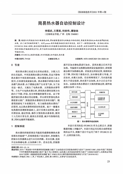
LCD1
LMO 16L
R1
10k
TemF:42.00°C 4?
■42.01 GND • •
Water 1evel!L H
DS18B20 温度传鏗器
目导辭]耳o目c 磅
XTAL1 XTAL2
p1 e
p1 p1
j
pp11.32
p1
p1.4
p1<5
<6
<7
PO.O/ADO PO.1/AD1 P0.2/AD2 PO.3/AD3 P0.4/AD4 P0.5/AD5 P0.6/AD6 FO.7/AD7
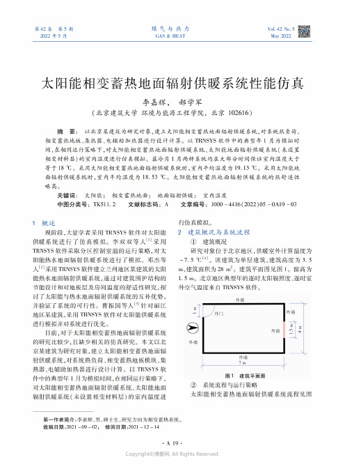
高
高 低
加極电器
关 关 开 关 开 关 关 开
加热继电器 加热指示灯
关 关 关 开 关 关 关 关
红外遥控控制热水器总开关,在此模拟设计中 用面包板电路进行红外遥控自动热水器开关测试。 通过实验红外遥控电路控制热水器总开关继电器的
通电,总电源指示灯亮(图7),反之断电时,总电源指 示灯灭。证明实验红外遥控器操作成功,便于达到用 户的安全操作目的。
中图分类号:TH122
文献标识码:A
文章编号:1672-545X( 2021 )04-0023-04
0引言
现在热水器已经成为生活的必需品,方便人们 的生活起居。中国发展热水器比外国晚,但这不影响 热水器在中国发展的速度。热水器最先是在工业上 使用,后来演变成家庭电器。热水器最早研制出来的 是燃气热水器,由于燃烧过程产生有害气体,为了改 变这一缺点,又诞生了电热水器、太阳能热水器等 等。自生产出电热水器以来,研究热水器的发展方向 趋向于节能、环保、安全和智能控制等方面。由于智 能控制在热水器应用比较晚,所以研究智能电热水 器前景比较广,智能使热水器拥有更多的功能叫随 着我国家电下乡政策发布,有力地推动热水器的广 泛使用,也让热水器得到更好的发展。基于一般蓄水 电热器的原理框架基础上,设计实现自动控制,减少 外围设备,稳定性强,操作方便的热水器系统,便利 于人们的日常生活,提高生活质量,减少污染物的危 害,同时也做到节能减排。
27002350_太阳能相变蓄热地面辐射供暖系统性能仿真
GANG Wenlong,CHEN Xihui,XIAO Ziwei
Abstract: A reverse decomposition method of cooling load based on random forest algorithm is pro-
大于40 ℃或房间室内温度大于18 ℃时,关闭集热
水泵、电辅助加热器。热源侧水泵、用户侧水泵始终
开启。
为9.0 W/(m2·K)。地板表面层为大理石,厚度为
20 mm,热导率为2.91 W/(m·K)。相变材料层厚
度为10 mm,Байду номын сангаас变材料采用石蜡,物性参数见表2。 埋管层回填混凝土厚度为25 mm,热导率为1.74
度恒定。忽略各相邻层的接触热阻。忽略埋管壁热
阻。
采用TRNSYS软件进行相变蓄热地板模块的设
置时,将相变蓄热地板分为3部分∶部分1为地板表
面层,部分2为相变材料层,部分3为埋管层。将地
板表面层下表面、埋管层上表面的热流量施加在相 变材料层上。基于以上思路,在 TRN-Build(用于 创建和编辑 TRNSYS 建筑模型所需的所有非几何信 息的界面)中由上至下设置3个模块∶最上面的为
posed. The steps of this method are introduced,and the
decomposition effect of this method is verified com- bined with an example of an office building. The de- composition model for cooling load based on random
Spears EverTUFF CTS CPVC 热水和冷水管道系统说明书

Special Pipe - Spears® CTSSpears®EverTUFF® Copper Tube Size (CTS) CPVC is a complete hot and cold water plumbing system consisting of pipe, fittings and solvent cement for plumbing applications. Spears®EverTUFF® CTS CPVC pipe is easily joined using solvent cement welding, is light weight, thermally efficient and code approved to provide cost-effective long-term system service.Product StandardsSpears®EverTUFF® CTS pipe and fittings are manufactured in strict compliance to ASTM D 2846, Standard Specification for Chlorinated Poly (Vinyl Chloride) (CPVC) Plastic Hot and Cold-Water Distribution Systems. This standard defines requirements for materials, workmanship, dimensions, tolerances, pressure-bearing capability, and thermocycling resistance. Spears®EverTUFF® CTS SDR 11 plumbing pipe and fittings are manufactured to specifications in accordance with this standard. SDR series pipe is based on an outside-diameter-to-wall thickness ratio. This is a constant regardless of pipe diameter, therefore all sizes of pipe carry the same pressure rating of 100 psi @ 180°F and is suitable for use with commercial hot water. Performance TestingSpears®EverTUFF® CTS CPVC pipe is tested and independently certified by NSF International to the requirements of ASTM D 2846 under NSF® Standard 14 and for use in potable (drinking) water service under NSF® Standard 61.Code ApprovalsMajor building codes have approved the use of CPVC piping as an acceptable material for plumbing systems, provided the piping conforms to applicable industry standard's and has been listed by a third party for conformance to NSF® Standard 14 and/or NSF®Standard 61 requirements. Code bodies that accept the use of CPVC include BOCA National Plumbing Code, National Standard Plumbing Code, SBCCI Standard Plumbing Code, International Plumbing Code, and the Uniform Plumbing Code to name a few. The user should determine approval and installation requirements according to local code having jurisdiction prior to use. DimensionsCPVC CTS Series pipe shall be manufactured in strict accordance to the requirements of ASTM D 2846 to SDR 11 dimensions and tolerances. Each production run of pipe manufactured in compliance to this standard, shall also meet or exceed the test requirements for materials, workmanship, burst pressure, flattening resistance, and extrusion quality and dimensions as defined in ASTM D 2846. This pipe shall be produced in CTS diameters (1/2" through 2" sizes) to SDR 11 specifications.NominalPipeSize (in.)AverageO.D.O.D.TOLAverageI.D.Min.WallRating @Wt./ft.PSI PressureRating @73°F180°F 1/20.625±.0030.4690.0680.0904001003/40.875±.0030.6950.0800.1494001001 1.125±.0030.9010.1020.2404001001-1/4 1.375±.003 1.1050.1250.3534001001-1/2 1.625±.004 1.3090.1480.4894001002 2.125±.004 1.7160.1930.829400100 PIPE SIZES SHOWN ARE MANUFACTURED IN STRICT COMPLIANCE WITH ASTM D 2846 ASTM STANDARD D 1784 MATERIAL EQUIVALENTS: Cell Classification 23447 = PVC Type IV Grade I CPVC = CPVC 4120Pressure RatingsThe Spears® CPVC system, including the joint, has a continuous rated working pressure of 100 psi at 180°F or 400 psi at 73°F. CPVC systems have the capability to withstand short term temperature/pressure increases above 100 psi at 180°F, as evidenced by their ability to consistently surpass the 48-hour, 150-psi Uniform Building Code test at 210°F. CPVC pipe should not be used where temperatures will consistently exceed 180°F.Pressure-Temperature De-Rating FactorsFor CTS CPVC 4120 SDR 11 Piping Systems°F Factor Rating, PSI73 1.0040080 1.00400900.913601000.823251200.652601400.502001600.401601800.25100The pressure de-rating factor is the same for all pipe sizes. Example: Determine the maximum allowable operating pressure for a CTS CPVC piping system with an operating temperature of 140°F. Using de-rating factor of 0.50 for 140° from the above chart, the maximum allowable operating pressure = 400 x 0.50 = 200 psi.InstallationInstallation shall be in accordance with the requirements of the local code having jurisdiction, the solvent cement manufacturer recommendations, and Spears® publication CTS-3, CPVC CTS Products Design and Installation Manual.Joining MethodsSpears®EverTUFF® CTS CPVC pipe is easily joined by standard solvent cementing process, threaded connections and flange assembly Solvent Cement Welding.Made in the U.S.A.Suitable for Oil-Free air handling to 25 psi, not for distribution of compressed air or gasSee Spears® Product Sourcebook for product offerings Page 68Hot & Cold Water Distribution SystemsSpecial Pipe - Spears® CTSSolvent Cement WeldingThis is the most common joining method used with CTS CPVC. See Installationsection for industrial pressure pipe for basic solvent cementing guidelines.CTS Solvent Cement SelectionCodes require use of solvent cement conforming ASTM F 493 and designatedspecifically for use with CTS CPVC products in accordance with ASTM D 2846.Spears®EverTUFF® CTS-5 CTS CPVC "One-step" (primerless) cements maybe used without primer if codes permit, or may be used with a primer whererequired by code. - Always CHECK LOCAL CODES.Set and Cure TimesPipe and fitting joint assembly must be allowed to set without any stress on thejoint for one to five minutes depending on the pipe size and temperature.Following the initial set period, the assembly can be handled carefully.FOLLOW THE CEMENT MANUFACTURER'S RECOMMENDED CURE TIMESPRIOR TO PRESSURE TESTING. - FAILURE TO DO SO WILL RESULT INJOINT FAILURE.Minimum Cure Time Prior to Testing at 150 psi with ColdWater (based on use of one-step CPVC cement or two-stepcement systems)Pipe Size (in.)Ambient Temperature During Cure Time>60°F40°F - 60°F<40°F3/8 1 hr 2 hrs 4 hrs1/2 1 hr 2 hrs 4 hrs3/4 1 hr 2 hrs 4 hrs1 1 hr2 hrs 4 hrs1-1/4 2 hrs 4 hrs8 hrs1-1/2 2 hrs 4 hrs8 hrs2 2 hrs 4 hrs8 hrs •NOTE Wait 24 hours prior to putting system into hot water service when installed at cure temperatures above 60°F; wait 48 hours prior to putting system into hot water service when installed at cure temperatures below 40°F Solvent Cement Joining.Wall PenetrationBuilding codes require that a fire-rated wall or floor must be sealed back to its original integrity when penetrated. Several sealants and materials are suitable for use with Spears®EverTUFF® CTS CPVC pipe to construct an appropriate UL Classified fire-rated penetration system. When installed properly, these systems will provide a two-hour fire rating. Consult local building code requirements.•NOTE Caution: Certain fire-stopping sealants and components contain stress cracking agents and other chemicals which may cause damage to CPVC piping; contact the appropriate manufacturer for compatibility with CPVC prior to use.•NOTE When installing CPVC in areas where the system must be drained to protect it from freezing, the lines must be sloped to drain.Underslab InstallationsSpears®EverTUFF® CTS CPVC products are approved for underslab installations (with joints) in all model-plumbing codes. When performing underslab installations, it is important to support the tube evenly on a smooth surface. The bedding and backfill should be sand or clean soil that is free from sharp rocks and other debris that could damage the pipe.Underslab installations that contain joints must be pressure tested before pouring the slab. NOTE: IAPMO IS 2098, "Installation Standard for CPVC Solvent Cemented Hot and Cold Water Distribution Systems," requires a test at 150 psi for 2 hours. The pipe should be sleeved where it penetrates the slab, along with construction joints within the slab. Spears®EverTUFF® CTS pipe is also manufactured in coils for underslab installations to eliminate joints. When turning coiled pipe up through a slab, into walls, etc., make sure the pipe does not kink. Sections of pipe that contain kinks must be cut out and replaced. Freeze Protection/Sunlight ExposureCPVC piping must be protected from freezing in all installation locations. Attention shall be paid to local insulating techniques and codes that require a particular method. Use only methods and materials suitable for use with CPVC piping. Where freezing is not an issue, CPVC shall not be installed so as to be subject to direct sunlight after installation and not installed on the surface of a building, unless protected by a covering or a chemically compatible paint, such as water based Latex.Hose Bibb InstallationHose bibbs are to be connected only to metal system components which are adequately anchored to the building structure. CPVC plastic systems must terminate in the wall.Water Heater ConnectionsBefore attempting to use Spears®EverTUFF® CTS CPVC in water heater connections, determine if local plumbing codes contain detailed requirements for connections to gas or electric storage-type heaters.DO NOT use Spears®EverTUFF® CTS CPVC products with commercial-type, non-storage water heaters.For areas where local plumbing codes do not have requirements, the following information can be used as a guide for water heater connections:• On electric water heaters, CPVC can be joined directly to the heater, using metal-to-CPVC transition fittings.• On high-efficiency gas water heaters that use plastic vent piping, CPVC can be joined directly to the heater in the same way as an electric water-heater connection.• On all other gas water heaters, there should be at least 6" of clearance between the exhaust flue and any CPVC tubing. A minimum of 6" metallic pipe should connect directly to the heater so that the CPVC tubing cannot be damaged by the buildup of excessive, radiant heat from the flue.• A temperature/pressure relief valve should be installed so that the sensing element contacts the water at the top of the heater.Page 69Suitable for Oil-Free air handling to 25 psi, not for distribution of compressed air or gas Spears® Manufacturing CompanySee Spears® Product Sourcebook for product offeringsSpecial Pipe - Spears ®CTS• Spears ®EverTUFF ® CTS CPVC products are approved by all model codes for use as relief-valve drain lines. A metal-to-CPVC transition fitting should be used to connect the tubing to the relief valve, with the tubing continued to the outlet. Both horizontal and vertical pressure relief drain should be supported every 3 feet. For horizontal runs, slope the tubing toward the outlet. Pipe must discharge to the atmosphere at an approved location.• Instantaneous water heaters (i.e., under sink units) require at least 6" of metallic pipe connected to heater inlet and no CVPC installed downstream.TRANSITION JOINTS AND FITTINGSSpears ®EverTUFF ® CTS CPVC pipe can be connected to copper, brass, valves, and other materials using a variety of transition fittings including unions, compression fittings, specially reinforced male and female adapters, flanged joints, grooved joints and other readily available transition fittings.Do not thread CPVC pipe and do not use regular CPVC female threaded fittings. Regular CPVC male threaded fittings shall only be used on cold waterapplications. Special reinforced male adapters, female adapters and otherfittings with brass threads are recommended for hot water applications andthreaded transitions to metal pipe. All approved threaded CPVC joints must beaccessible. (See also Water Heater Connections section for additional installation details).Standard compression fittings with brass ferrules can be used; however, PTFE tape must be applied over the brass ferrule to compensate for the dissimilarthermal expansion rates between the brass and CPVC. Caution must beexercised to prevent over tightening of compression fittings. Use extreme care when soldering any metal system to prevent flame contact with or heat distortion in CPVC pipe and fittings.Assembling Threaded Connections Threaded connections require the application of a thread sealant that is compatible with CPVC material. Spears ® recommends the use of Spears ®BLUE 75™ Thread Sealant. Apply sealant to the male threads only. Make sure all threads are covered. DO NOT clog the waterway with excess sealant. If PTFE tape is used, Spears ® recommends a thickness of at least .0035" that meets or exceeds military specification, MIL-T-27730A. DO NOT use a combination of tape and thread sealant on the same joint. Apply PTFE tape in the direction of the threads by starting with the first full thread and continuing over the entire thread length. Make sure all threads are covered. Generally, 2 - 3 wraps are sufficient to produce a watertight connection.DO NOT over-torque any threaded connections. Generally, one to two turns beyond finger-tight are required for a threaded connection. Factory testing hasindicated that 10 - 25 ft-lbs of torque is adequate to obtain a leak-free seal.Spears ® recommends the use of a strap wrench when installing threadedconnections.Hanger/Support SpacingSpears ®EverTUFF ® CTS CPVC pipe is rigid, it requires fewer supports than flexible, plastic systems. Vertical runs should be supported at each level so that the weight of the run is not placed on a fitting or a joint. Horizontal runs require support every 3 feet for 1/2" - 1" diameter pipe and every 4 feet for 1-1/4" and larger diameters. Support spacing should be in accordance with applicable local codes. Horizontal runs must be braced so that the stress loads (caused by bending or snaking) will not be placed on a fitting or a joint. Hanger support spacing information is shown in Table A.Spears ® recommends that hangers, designed for supporting CPVC, be used tosupport CPVC piping. However, some hangers, designed for steel pipe, may be used if their suitability is clearly established. These hangers must be selected toaccommodate the specific pipe size. In addition, they cannot contain rough orsharp edges that contact the pipe, and they must not bind the pipe from axial movement that is caused by expansion and contraction.Pipe Size (in.)Maximum Hanger Support Spacing 3/8 3 ft 1/2 3 ft 3/4 3 ft13 ft 1-1/4 4 ft 1-1/2 4 ft 24 ft Thermal Expansion All piping systems expand and contract with changes in temperature. This issue must be addressed with appropriate system design to prevent damage to thesystem. Spears ®EverTUFF ® CTS CPVC pipe will expand or contract approximately 3.8 inches per 100 feet of pipe with every 100°F of temperaturerise or fall. The effects of expansion/contraction are usually absorbed by the system at changes of direction in the piping. In other words, long, straight runs of piping are more susceptible to experiencing measurable movement with changes in temperature. As with other piping materials, the installation of an expansion loop or offset is required on long, straight runs which will allow the piping system to absorb the forces generated by expansion/contraction without damage. The rate of expansion does not vary with pipe size. The effects of expansion/contraction are more pronounced on hot water lines. See Thermal Expansion & Contraction section under Engineering and Design Data for Industrial Piping in this manual for information on calculating movement andexpansion loops.System TestingOnce the system has been installed and allowed to cure properly, the systemshall be tested in accordance with applicable code requirements. When testingwith water (hydrostatic testing), the system must be slowly filled with water andthe air bled from the highest and furthest points in the system before test pressure is applied. Air must be removed from piping systems to prevent it from being locked in the system when pressure is applied. Failure to do so could beharmful to job site personnel should a failure occur. If a leak is found, the affected product must be cut out and discarded. A new section can be installedusing couplings or other approved means.Made in the U.S.A.Suitable for Oil-Free air handling to 25 psi, not for distribution of compressed air or gasSee Spears ® Product Sourcebook for product offeringsPage 70。
欧洲电器Split System热水器系统产品数据说明书

Product DataSplit System Heat Pump4TWR4017N1000A Array 4TWR4018N1000A4TWR4024N1000A4TWR4030N1000A4TWR4036N1000A4TWR4042N1000A4TWR4048N1000A4TWR4060N1000AN o t e:“Graphics in this document are for representationonly.Actual model may differ in appearance.”January202322-1765-13L-E NProduct Specifications(a)Certified in accordance with the Unitary Air-conditioner equipment certification program which is based on AHRI standard210/240.(b)Calculated in accordance with N.E.C.Only use HACR circuit breakers or fuses.(c)Reference the outdoor unit ship-with literature for refrigerant piping length and lift guidelines.Reference the refrigerant piping software pub#32-3312-xx or refrigerant piping application guide SS-APG006-xx for long line sets or specialty applications(xx denotes latest revision).(d)The outdoor condensing units are factory charged with the system charge required for the outdoor condensing unit,ten(10)feet of tested connecting line,and the smallest rated indoor evaporative coil match.Always verify proper system charge via subcooling(TXV/EEV)or superheat(fixed orifice)per the unit nameplate.(e)25,30,35and50foot linesets available.For a complete listing of lineset options available from equipment or supply stores,refer to the Trane Residentialand Light Commercial Product Handbook.P r o d u c t S p e c i f i c a t i o n s(a)Certified in accordance with the Unitary Air-conditioner equipment certification program which is based on AHRI standard210/240.(b)Calculated in accordance with N.E.C.Only use HACR circuit breakers or fuses.(c)Reference the outdoor unit ship-with literature for refrigerant piping length and lift guidelines.Reference the refrigerant piping software pub#32-3312-xx or refrigerant piping application guide SS-APG006-xx for long line sets or specialty applications(xx denotes latest revision).(d)The outdoor condensing units are factory charged with the system charge required for the outdoor condensing unit,ten(10)feet of tested connecting line,and the smallest rated indoor evaporative coil match.Always verify proper system charge via subcooling(TXV/EEV)or superheat(fixed orifice)per the unit nameplate.(e)25,30,35and50foot linesets available.For a complete listing of lineset options available from equipment or supply stores,refer to the Trane Residentialand Light Commercial Product Handbook.P r o d u c t S p e c i f i c a t i o n sAccessory Description and UsageA n t i-S h o r t C y c l e T i m e r—Solid state timing device that prevents compressor recycling untilfive(5)minutes have elapsed after satisfying call or power e in area withquestionable power delivery,commercial applications,long lineset,etc.E v a p o r a t i o n D e f r o s t C o n t r o l—SPST Temperature actuated switch that cycles the condenseroff as indoor coil reaches freeze-up ed for low ambient cooling to30°F with TXV.R u b b e r I s o l a t o r s—Five(5)large rubber donuts to isolate condensing unit from transmittingenergy into mounting frame or e on any application where sound transmission needs tobe minimized.H a r d S t a r t K i t—Start capacitor and relay to assist compressor motor e in areas withmarginal power supply,on long linesets,low ambient conditions,etc.E x t r e m e C o n d i t i o n M o u n t K i t—Bracket kits to securely mount condensing unit to a frame orpad without removing any e in areas with high winds,or on commercial roof tops,etc.A H R I S t a n d a r d C a p a c i t y R a t i n g C o n d i t i o n sAHRI Standard210/240Rating Conditions1.Cooling80°F DB,67°F WB air entering indoor coil,95°F DB air entering outdoor coil.2.High Temperature Heating47°F DB,43°F WB air entering outdoor coil,70°F DB air enteringindoor coil.3.Low Temperature Heating17°F DB air entering indoor coil.4.Rated indoor airflow for heating is the same as for cooling.A H R I S t a n d a r d270R a t i n g C o n d i t i o n s—(Noise rating numbers are determiend with the unit incooling operations.)Standard Noise Rating number is at95°F outdoor air.Model NomenclatureTRANE3 = 134 = 145 = 15Schematic DiagramsFigure 1.017N,030N &036NModelsFigure 2.017N,030N &036NModelsS c h e m a t i c D i a g r a m sFigure 3.018N,024N,042N,048N &060NModelsS c h e m a t i c D i a g r a m sFigure 4.018N,024N,042N,048N &060NModelsS c h e m a t i c D i a g r a m sOutline DrawingMechanical Specification OptionsG e n e r a lThe outdoor condensing units are factory charged with the system charge required for theoutdoor condensing unit,ten(10)feet of tested connecting line,and the smallest rated indoorevaporative coil match.This unit is designed to operate at outdoor ambient temperatures as highas115°F.Cooling capacities are matched with a wide selection of air handlers and furnace coilsthat are AHRI certified.The unit is certified to UL1995.Exterior is designed for outdoorapplication.C a s i n gUnit casing is constructed of heavy gauge,galvanized steel and painted with a weather-resistantpowder paint finish.The corner panels are prepainted.All panels are subjected to our1,000hoursalt spray test.R e f r i g e r a n t C o n t r o l sRefrigeration system controls include condenser fan,compressor contactor and low and highpressure switches.A factory supplied,field installed liquid line drier is standard.C o m p r e s s o rThe compressor features internal over temperature and pressure protection.Other featuresinclude:Centrifugal oil pump and low vibration and noise.C o n d e n s e r C o i lThe outdoor coil provides low airflow resistance and efficient heat transfer.The coil is protectedon all four sides by louvered panels.L o w A m b i e n t C o o l i n gAs manufactured,this system has a cooling capacity to55°F.The addition of an evaporatordefrost control permits operation to40°F.The addition of an evaporator defrost control with TXVpermits low ambient cooling to30°F.The addition of the BAYLOAM107A low ambient kit permits ambient cooling to20°F.T h e r m o s t a t s–Cooling only and heat/cooling(manual and automatic change over).Sub-base tomatch thermostat and locking thermostat cover.22-1765-13L-EN11Trane-by Trane Technologies(NYSE:TT),a global innovator-creates comfortable,energy efficient indoor environments for commercial and residential applications.For more information,please visit or .The AHRI Certified mark indicates Trane U.S.Inc.participation in the AHRI Certification program.For verification of individual certified products,go to ahridirectory. org.Trane has a policy of continuous data improvement and it reserves the right to change design and specifications without notice.We are committed to using environmentally conscious print practices.22-1765-13L-EN12Jan2023Supersedes22-1765-13K-EN(August2022)©2023Trane。
海尔 JSQ22-12MODEL(12T)U1 12升变频恒温燃气热水器 使用说明书

·使用前请仔细阅读本说明书·本公司保留说明书解释权·产品外观请以实物为准·阅后请与发票一并妥善保存·如遇产品技术或软件升级,恕不另行通知·本产品只适合在中国大陆销售和使用·该系列家用燃气热水器执行国家标准:GB 6932-2015地址:山东省青岛市黄岛区海尔工业园青岛经济技术开发区海尔热水器有限公司版次:2023年 第1 版专用号:0040511316检验印章:产品合格证产品名称:见铭牌/条码产品型号:见铭牌/条码出厂编号:见铭牌/条码检验日期:见铭牌/条码检验结论: 检验合格准予出厂使用说明书家用燃气快速热水器JSQ25-13S1(12T)U1JSQ25-13DKS(12T)U1JSQ30-16DKS(12T)U1JSQ25-13WG3(12T)U1JSQ30-16WG3(12T)U1JSQ22-12WG3MWCU1JSQ22-12MODEL(12T)U1JSQ25-13MODEL(12T)U1JSQ30-16MODEL(12T)U1型号:智能家电操控智慧场景定制智家商城购物家电报装报修“1+5”成套服务尊敬的用户:感谢您选择和使用我们的产品。
我们承诺:您的产品需要安装或维修等服务时,我们将为您提供:“1+5″的成套服务:1:一次就好服务。
5:五项增值服务:(1)安全测电服务:为您提供安全测电并提醒讲解到位服务;(2)讲解指导服务:向您讲解产品使用、保养常识,指导用户正确使用服务;(3)一站通检服务:服务好本产品,对家中其他本企业产品进行通检服务;(4)全程无忧服务:为您提供设计、送货、安装、清洗、延保、以旧换新等服务;(5)现场清理服务:服务完成后将服务现场清理干净。
为体现真诚、贴心,我们友情提醒:产品的安装服务,因用户的安装环境、个性需求不同,安装过程中如需辅加材料或有特殊服务项目需要支付材料等费用,您可以通过“海尔智家”APP-“智家服务”-“收费标准”进行查看,并给予监督。
全自动软化水控制器操作说明

全自动软化水控制器操作说明产品概述Model2750迷你经济型投资最少占地最省安装简便管理集中适用于水质稳定,原水硬度较低或对水质要求不需很高的用户,如小型洗衣房、补水量较稳定的锅炉房,同时也是追求高品质生活的家庭、别墅用水的明智选择。
Model2850经济实用型投资适中水量充足节约占地便于管理适用于中等需水量的宾馆饭店、洗衣房、锅炉房等。
Model2900动力设备伴侣型特别加装了硬水止通阀,在还原期间自动关闭软化水进水口,保证没有硬水通过。
使锅炉运行更安全、更可靠。
适用于蒸汽锅炉和大型热水锅炉。
Model3900超量供水实力型设计优良的控制系统,庞大的树脂罐,保证了最大可达60立方米/小时的额定流量,也特别加装了硬水止通阀,既保证水量也保证水质。
适用于用水量大的集中供热锅炉房或热交换站。
电子式控制器操作说明流量型调整步骤一、调时钟:接通电源,显示器即显示现在时刻,如不是现在时刻,通过调整▲▼键,调到现在时刻。
二、设定周期制水量:首先按程序键,程序指示灯亮后再按程序键,按到周期制水量灯亮时,按▲▼键调整所需设定的周期制水量。
三、设定再生时间:1. 反洗时间设定:设定完周期制水量后,按程序键“反洗”指示灯亮,按▲▼键调整反洗时间;2. 吸盐/慢洗时间设定:反洗时间设定后,按程序键“吸盐/慢洗”指示灯亮,按▲▼键调整吸盐慢洗时间;3. 快洗时间设定:吸盐/慢洗时间设定后,按程序键“快洗”指示灯亮,按▲▼键调整快洗时间;4. 注水时间设定:快洗时间设定后,按程序键向盐罐“注水”指示灯亮,按▲▼键调整向盐罐注水时间。
四、调到工作状态:向盐罐注水时间设定后,按程序键回到时钟显示,控制器处于工作状态。
时间型调整步骤一、首先调到时间型设定状态:控制器在断电的情况下,先按住程序键然后接通控制器电源,10秒钟后停止按键,显示器显示数是1(1是流量型程序),按▲▼键让显示器显示数为2(2是时间型程序),然后按程序键程序指示灯亮,显示器显示字母D,按▲▼键调整1天或99天内再生一次;设定后按程序键显示器显示字母H,按▲▼键调整24小时内的任意一个再生时间(比如0点或23点)。
Series 490W 无线热水系统差压测量仪说明说明书
Series 490W Wireless Hydronic Differential Pressure Manometer is the most accurate and easy to operate manometer on the market. By using wireless transducers and a versatile handheld, a single operator can monitor and balance a hydronic system in less time than traditional hydronic balancers. The Series 490W utilizes mobile technology to communicate via a Bluetooth connection with the transducers to monitor differential pressure and flow on up to three different valves. Being wireless means there are no hoses to carry, snag on equipment or needing to be drained. The 490W includes the Dwyer Hydronic Application Software that contains valve charts for numerous manufacturers, which converts differential pressure to flow directly on the screen.• Rugged weatherproof handheld housing withstands 1.5 meter drop test • Wireless measurement of differential pressure, single pressure and air flow• Ergonomic design is much lighter and easier to work with, providing greater maneuverability and quick install setup• Refrigerant pressure testing • Hydronic valve balancing• Measure pressure drop across pumps• Measure pressure drop across chiller and coils for freeze protectionFEATURES/BENEFITSSPECIFICATIONSWireless DistanceUp to 65´ (19.8 m).ServiceCompatible gases and liquids.Wetted Materials316 SS, PTFE, brass.Accuracy2% of reading, ±1 pensated Temperature Range14 to 140°F (-10 to 60°C).Pressure Hysteresis±0.25% FS.Pressure Limits0-50 psi and 0-200 psi (see chart for more ranges).Process Temperature Limits-4 to 185°F (-20 to 85°C).Display 5˝ Gorrilla ® glass 3, touch screen, 1280x720.Resolution0.01 psi.Process Connections Two 1/4˝ male NPT.Power RequirementsCR2050 lithium battery, user replaceable.Weight2 lb (907 g).Agency ApprovalsCE, FCC.DESCRIPTIONAPPLICATIONSSERIES 490W | WIRELESS HYDRONIC DIFFERENTIAL PRESSURE MANOMETER®DIMENSIONSSERIES490W: Wireless hydronic differential pressure manometer RANGE-6: 0 to 50 and 0 to 200 psi OPTION-NIST: NIST calibration certificateKIT-HKIT: Hydronic balancing kit490W-6-HKIT-NISTHOW TO ORDERUse the bold characters from the chart below to construct a product code.ACCESSORIESModel DescriptionA-490W-1A-490W-2A-490W-3A-490W-4A-490W-5A-490W-6A-HKIT-500A-HKIT-500XL A-HKIT-5100 to 15 psid replacement sensors [2 paired sensors]0 to 30 psid replacement sensors [2 paired sensors]0 to 50 psid replacement sensors [2 paired sensors]0 to 100 psid replacement sensors [2 paired sensors]0 to 500 psid replacement sensors [2 paired sensors]0 to 200 psid replacement sensors [2 paired sensors]Piercing gage adapter, 1/8˝ dia x 1-1/2˝ length (2 per kit)Piercing gage adapter, 1/8˝ dia x 3˝ length (2 per kit)Piercing gage adapter, 1/16˝ dia x 1-1/2˝ length (2 per kit)3-17/64 [83]6-17/64[159]5/8[16]1.0002.940.944HEX©Copyright 2020 Dwyer Instruments, Inc.Printed in U.S.A. 12/20DS-490W Rev. 3ORDER ONLINE TOD DWYER INSTRUMENTS, INC.Important Notice: Dwyer Instruments, Inc. reserves the right to make changes to or discontinue any product or service identified in this publication without notice. Dwyer advises its customers to obtain the latest version of the relevant information to verify, before placing any orders, that the information being relied upon is current.Gorilla ® is a registered trademark of Corning, Incorporated。
nVent Raychem HWAT 混合热水系统规格指南说明书
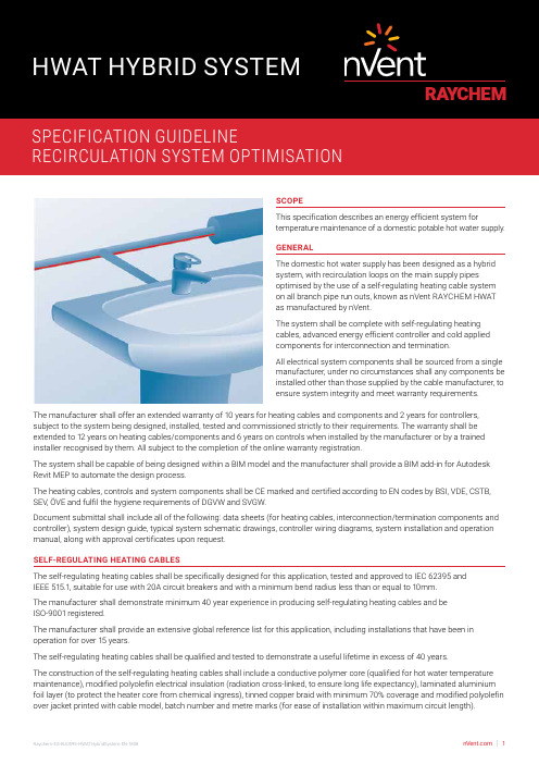
SCOPEThis specification describes an energy efficient system fortemperature maintenance of a domestic potable hot water supply.GENERALThe domestic hot water supply has been designed as a hybridsystem, with recirculation loops on the main supply pipesoptimised by the use of a self-regulating heating cable systemon all branch pipe run outs, known as nVent RAYCHEM HWATas manufactured by nVent.The system shall be complete with self-regulating heatingcables, advanced energy efficient controller and cold appliedcomponents for interconnection and termination.All electrical system components shall be sourced from a singlemanufacturer, under no circumstances shall any components beinstalled other than those supplied by the cable manufacturer, toensure system integrity and meet warranty requirements.The manufacturer shall offer an extended warranty of 10 years for heating cables and components and 2 years for controllers, subject to the system being designed, installed, tested and commissioned strictly to their requirements. The warranty shall be extended to 12 years on heating cables/components and 6 years on controls when installed by the manufacturer or by a trained installer recognised by them. All subject to the completion of the online warranty registration.The system shall be capable of being designed within a BIM model and the manufacturer shall provide a BIM add-in for Autodesk Revit MEP to automate the design process.The heating cables, controls and system components shall be CE marked and certified according to EN codes by BSI, VDE, CSTB, SEV, ÖVE and fulfil the hygiene requirements of DGVW and SVGW.Document submittal shall include all of the following: data sheets (for heating cables, interconnection/termination components and controller), system design guide, typical system schematic drawings, controller wiring diagrams, system installation and operation manual, along with approval certificates upon request.SELF-REGULATING HEATING CABLESThe self-regulating heating cables shall be specifically designed for this application, tested and approved to IEC 62395 andIEEE 515.1, suitable for use with 20A circuit breakers and with a minimum bend radius less than or equal to 10mm.The manufacturer shall demonstrate minimum 40 year experience in producing self-regulating heating cables and beISO-9001 registered.The manufacturer shall provide an extensive global reference list for this application, including installations that have been in operation for over 15 years.The self-regulating heating cables shall be qualified and tested to demonstrate a useful lifetime in excess of 40 years.The construction of the self-regulating heating cables shall include a conductive polymer core (qualified for hot water temperature maintenance), modified polyolefin electrical insulation (radiation cross-linked, to ensure long life expectancy), laminated aluminium foil layer (to protect the heater core from chemical ingress), tinned copper braid with minimum 70% coverage and modified polyolefin over jacket printed with cable model, batch number and metre marks (for ease of installation within maximum circuit length).[Select One Option][Option 1]The self-regulating heating cable shall be nVent RAYCHEM HWAT-R and provide pipe maintained temperatures in the range 50-65°C [Option 2]The self-regulating heating cable shall be nVent RAYCHEM HWAT-M and provide pipe maintained temperatures in the range 50-55°C INTERCONNECTION AND TERMINATION COMPONENTSInterconnection and termination shall be with cold applied insulation displacement connectors and gel type end seals, which are UV resistant, IP68 and 65°C rated, suitable for 2500Vdc insulation resistance test, with Torx head fittings for ease of installation and both audible & visual installation confirmation, known as RayClic, manufactured by nVent.THERMAL INSULATIONInsulation selection and thickness shall be strictly in accordance with the self-regulating heating cable system design guide,with variations in ambient temperature fully considered. Insulation sections shall be applied without delay after the heating cable installation, affixed with suitable warning labels less than 3 m apart on alternate sides and visible from all sections.ENERGY EFFICIENT, CONTROL SYSTEM[Select One Option](Option 1)Multi-Circuit, Multi-Application Distributed Digital Control SystemAll hot water temperature maintenance circuits shall be controlled and monitored using a centralised control system with distributed power and control modules, known as nVent RAYCHEM ACS-30, complete with integrated HWAT ECO, manufactured by nVent.The centralised control system shall provide pre-programmed parameters to provide concurrent control for heating cables used for hot water temperature maintenance, pipe freeze protection, flow maintenance, surface snow melting, roof and gutter de-icing and floor heating applications.The control & monitoring system shall be modular for easy design and include:[select some or all of the following product modules]User Interface Terminal (UIT): a colour touch-screen central user interface terminal for control and monitoring up to 260 heating cable circuits, known as ACS-30-EU-UIT2, manufactured by nVent [always included in the system]Power Connection Module (PCM): to provide distributed power connection, control and monitoring of heating cable circuits, and integrated electrical protection, known as ACS-30-EU-PCM2, manufactured by nVent [at least 1 PCM shall be included in the system, up to 52 PCMs may be connected to each UIT]Remote Monitoring Modules (RMM): to measure additional temperatures for control and monitoring of heating cable tracing circuits, known as ACS-30-EU-Moni-RMM2-E, manufactured by nVent [up to 16 RMM modules may be controlled via a single UIT, with up to 8 RTDs per RMM]The centralised control system shall have the following functions:Multiple circuit, multiple heating cable applicationsModular design and installation - to provide total flexibility, including any future building modificationsControl and monitoring of up to 260 heating cable circuits - through a single user interface terminal (UIT)Central programming through the UIT3 user programmable alarm relays for user specified communication of alarm conditionsProtoNode high performance protocol gateway connection to allow translation from native ModBus to BacNet protocols Distributed power control modules (PCMs) - for placement throughout the building or group of buildings, to provide power connection, circuit protection and integrated control & monitoring in proximity to all required heating cable applications and to limit the power cabling neededPCMs with 1 sensor input per circuit for individual circuit temperature monitoringRemote monitoring modules (RMMs) - to measure additional temperatures for control and monitoringRMMs with up to 8 additional resistance temperature detectors (RTDs)UIT communication with up to 52 PCMs and up to 16 RMMsPCMs shall additionally• Provide 5, 10 or 15 circuits with integrated electrical and circuit protection (either 20A or 32A)• Contain control logic circuitry to ensure continuity of heating cable operation in the event of power failure orcommunication failure with the UIT• Provide circuit by circuit monitoring of line or ambient temperature, energy consumption, energy usage pattern andground fault/earth fault detection• Enable circuit by circuit alarm function, with the UIT providing details of the alarm, the circuit(s) affected and capture automatically in the event log.• Connect to the UIT via RS-485 cable for communication, control & monitoring purposesThe control system shall be compliant with IEC61439 and be tested and CE approved to this standard.The integrated energy efficiency controller shall have the following functions:Adjustable maintenance temperatures in the range 50-65°CWater heater temperature sensor (HWS flow temp) and alarm systemIntegrated power off timer function with 7 day programmable temperature versus time function, 8 editable built-in building specific programs for temperature maintenance, thermal shock program (for use with HWAT R), automatic summer/winter time and leap year correctionVisible and audible alarm5" Colour touch screen user interfacePassword protectionIP54 rated(Option 2)Single Circuit, Single Application ControllerAll self-regulating heating cable circuits shall be controlled with an energy saving thermostat, known as HWAT-T55, manufactured by nVent.The controller shall have the following functions:Digital display for pipe temperature and alarmPipe sensing temperature control with preset temperatures (55°C or 50°C)Maximum circuit length 50m3 operation modes (ON/ECO/OFF)Built in timer for ECO modeDIN rail mountable (35mm)EXECUTIONDesign DeliverablesThe manufacturer shall be able to provide heat loss calculations and corresponding selection of self regulating heating cables with variations in ambient temperature and pipe size and thermal insulation fully considered, system layout and schematic drawings indicating power connections, tees and end seals, electrical schedules indicating cable length and circuit protection, controller configuration listing and wiring diagrams.Installation DeliverablesThe self-regulating heating cables shall be installed in accordance with the design plans, ‘straight traced’ (i.e. not spirally wound) within the manufacturers defined maximum circuit lengths, tested and commissioned strictly in accordance with the manufacturer’s instructions. Installation of thermal insulation shall be closely coordinated with the responsible sub-contractors.[Select One Option][Option 1]The system shall be installed, tested and commissioned by the manufacturer.[Option 2]The system shall be installed and tested by installers trained and recognised by the manufacturer and then commissioned by the manufacturer.[Option 3]The system shall be installed, tested and commissioned by installers trained and recognised by the manufacturer.[Option 4]The system shall be installed, tested and commissioned under periodical supervision by the manufacturer.Electrical ConnectionAll connections between the electrical supply, control panel and self-regulating heating cable circuits shall be installed by an approved electrical contractor. All self-regulating heating cable circuits shall be electrically protected by MCB (BS EN 60898 type C or D) and RCD (30 mA sensitivity, tripping within 100ms).ENGINEERING DRAWING NOTESThe domestic hot water supply has been designed as a hybrid system, with recirculation loops on the main supply pipes optimised by the use of a self-regulating heating cable system on all branch pipe run outs, known as nVent RAYCHEM HWAT as manufactured by nVent.Interconnection and termination shall be with cold applied insulation displacement connectors and gel type end seals, which are UV resistant, IP68 and 65°C rated, suitable for 2500Vdc insulation resistance test, with Torx head fittings for quality of closure and both audible & visual installation confirmation, known as RayClic, manufactured by nVent.The circuits shall be controlled via an energy saving, programmable controller[Select One](Option 1)ACS-30 as manufactured by nVent(Option 2)HWAT-T55 as manufactured by nVentThe self-regulating heating cables shall be installed in accordance with the design plans, ‘straight traced’ (i.e. not spirally wound) within the manufacturers defined maximum circuit lengths, tested and commissioned strictly in accordance with the manufacturer’s instructions. Installation of thermal insulation shall be closely coordinated with the responsible sub-contractors.Insulation selection and thickness shall be strictly in accordance with the self-regulating heating cable system design guide, with variations in ambient temperature fully. Insulation sections shall be applied without delay after the heating cable installation, affixed with suitable warning labels less than 3 m apart on alternate sides and visible from all sections.All connections between the electrical supply, control panel and self-regulating heating cable circuits shall be installed by an approved electrical contractor.©2018 nVent. All nVent marks and logos are owned or licensed by nVent Services GmbH or its affiliates. All other trademarks are the property of their respective owners. nVent reserves the right to change specifications without notice.AustraliaTel +61 2 97920250Fax +61 2 97745931United KingdomTel 0800 969 013Fax 0800 968 624************************India - NoidaTel +91 120 464 9500Fax +91 120 464 9548*******************IrelandTel 1800 654 241Fax 1800 654 240*****************India - MumbaiTel +91 22 6775 8800/01Fax +91 22 2556 1491*******************South East AsiaTel +65 67685800Fax +65 67322263UAETel +971 4 378 1700Fax +971 4 378 1777*******************。