S+B主令选型说明
固态继电器最全的选型说明书

固态继电器最全的选型说明书固态继电器(SSR)是一种电子设备,用于在高电流和高压的电路中实现电气控制。
与传统的机械继电器相比,固态继电器具有更高的可靠性、更长的寿命和更快的响应时间。
在广泛的应用领域中,选择合适的固态继电器非常重要。
本选型说明书将详细介绍固态继电器的各项选择标准、技术参数以及适用范围,以帮助用户在购买和使用固态继电器时做出明智的决策。
一、固态继电器的基本原理和工作方式固态继电器是由光学隔离器、半导体设备和直流驱动电路组成的。
当控制端施加电压时,固态继电器的光电耦合器将输入信号转换为电流信号,并通过驱动电路送入半导体开关器件。
这样就可以控制负载端是否通电,实现电路的开关控制。
固态继电器可以替代传统的机械继电器,在高速、高精度、高可靠性的电气控制中发挥重要作用。
二、固态继电器的选择标准1.控制电压范围:固态继电器的控制电压范围应与用户的实际需求一致。
通常情况下,控制电压应在继电器的额定电压范围内。
如果控制电压过高或过低,将导致固态继电器无法正常工作或出现损坏。
2.负载电流范围:固态继电器的负载电流范围应与实际负载电流需求相匹配。
对于大功率负载,应选择具有较高额定电流的固态继电器,以确保其能够承受负载电流并保持稳定工作。
3.负载电压范围:固态继电器的负载电压范围应与实际负载电压需求相匹配。
如果负载电压超出固态继电器的额定电压范围,将导致继电器无法正常工作或引发安全事故。
4.控制输入类型:固态继电器的控制输入类型分为交流输入和直流输入。
用户应根据具体电路需求选择适合的控制输入类型。
5.继电器类型:固态继电器分为常闭型(NC)和常开型(NO)。
常闭型在继电器未通电时负载端通电,常开型在继电器未通电时负载端断电。
用户应根据实际需求选择适合的继电器类型。
三、固态继电器的技术参数1.额定负载电流:表示固态继电器能够承受的最大负载电流,单位为安培(A)。
2.额定负载电压:表示固态继电器能够承受的最大负载电压,单位为伏特(V)。
压力表选型说明
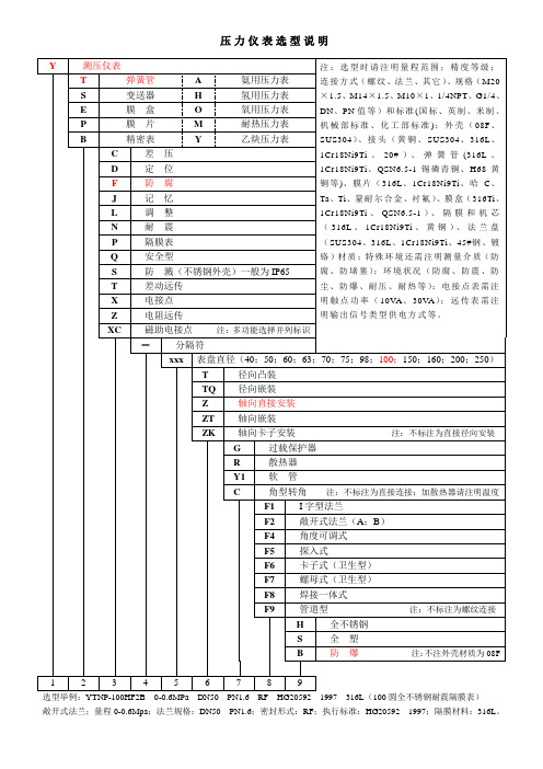
弹簧管
氨用压力表
S
变送器
H
氢用压力表
E
膜盒
O
氧用压力表
P
膜片
M
耐热压力表
B
精密表
Y
乙炔压力表
差压
D
定位
F
防腐
J
记忆
L
调整
N
耐震
P
隔膜表
Q
安全型
S
防溅(不锈钢外壳)一般为IP65
T
差动远传
X
电接点
Z
电阻远传
XC
磁助电接点注:多功能选择并列标识
-
分隔符
xxx
表盘直径(40;50;60;63;70;75;98;100;150;160;200;250)
径向凸装
TQ
径向嵌装
Z
轴向直接安装
ZT
轴向嵌装
ZK
轴向卡子安装注:不标注为直接径向安装
过载保护器
R
散热器
Y1
软管
C
角型转角注:不标注为直接连接;加散热器请注明温度
F1
I字型法兰
F2
敞开式法兰(A;B)
F4
角度可调式
F5
探入式
F6
卡子式(卫生型)
F7
螺母式(卫生型)
F8
焊接一体式
F9
管道型注:不标注为螺纹连接
全不锈钢
S
全塑
Bห้องสมุดไป่ตู้
防爆注:不注外壳材质为08F
1
2
3
4
5
6
7
8
9
选型举例:YTNP-100HF2B 0-0.6MPa DN50 PN1.6 RF HG20592 1997316L(100圆全不锈钢耐震隔膜表)
主要电气选型及参数说明

主要电气选型及参数说明
电气设备的选型是发电厂和变电所设计中的重要环节,需要确保供配电的安全可靠,同时追求技术的先进性和经济的合理性。
以下是电气设备选型及参数说明:
1. 高压电气设备选择的一般条件:
按正常工作条件选择:包括额定电压、最高工作电压、额定电流、频率、开断电流等。
按短路条件校验:包括动稳定和热稳定校验。
按环境工作条件选择:如温度、湿度、海拔等。
2. 三相交流电动机的额定电流计算:
经验公式:在380V电压下,额定电流=功率2。
理论公式:P=UI cosφ,其中cosφ为功率因数,一般取。
3. 交流接触器的选型:主触点额定电流一般为电动机额定电流的1到倍,通常选择倍的电动机额定电流。
4. 热继电器的选型:整定电流为倍的电动机额定电流。
5. 空气开关的选型:
额定电压必须大于等于线路额定电压。
额定电流和过电流脱扣器的额定电流(整定电流)大于等于线路计算负荷电流。
6. 其他注意事项:
根据装置地点、使用条件、检修和运行等要求,对电气设备进行种类和型式的选择。
当环境条件(如气温、风速、温度、污秽等级、海拔高度、地震烈度和覆冰厚度)超过一般电气设备使用条件时,应采取相应措施。
总的来说,电气设备的选型是一个复杂的过程,需要考虑多种因素,包括设备的工作条件、环境条件以及经济和技术要求等。
因此,在进行电气设备的选型时,建议咨询专业的电气工程师或相关专家进行评估和选择。
SVS PB-1000 SB-1000 有线发电机说明书

Thank you, and congratulations on purchasing your new SVS subwoofer!Prepare to be pleasantly shocked at what an SVS subwoofer will bring to your home music and theater system – we guarantee you a thrilling audio experience!SVSsubwoofers deliver bass so accurate, detailed, clean and dynamic - you'll hear andfeel things you never knew existed in your favorite movies and music.SVS audio products are designed to outperform competing consumer-direct and retail brands at every price point. By leveraging advanced technology, using the highestquality components, and applying rigorous engineering and design principles - theteam at SVS has created a line of premium audio products which bring music andmovies to life with stunning realism - all at truly affordable prices.SVS takes the guess work out of purchasing and setting up your new subwoofer. Our Sound Experts in customer service will help you select the best SVS subwoofer foryour specific application, and walk you through the entire set-up process to ensureyour new SVS and your entire system is performing optimally.With our unmatched customer service and the most comprehensive consumerprotection policies and warranty coverage in the industry (/bill-of-rights), you can rest easy knowing we're standing behind our products 100%. Yourcomplete satisfaction is our only goalIf you have any questions about your SVS product, please contact us directly.•***********************•(877)626-5623 owner’s manual v. 1.1_031820141IMPORTANT SAFETY INSTRUCTIONS 3 OPTIONS 4 PLACEMENTAMPLIFIER FEATURES & CONTROLS 5 AMPLIFIERDIAGRAM 5 FEATURES AND CONTROLS 6 POWER AND SIGNAL CONNECTIONS 8 A/V RECEIVER (AVR)/PROCESSOR (PRO) CONNECTION 8MULTI-CHANNEL/STEREO - LINE LEVEL CONNECTION 9-MULTI-CH ANNEL/STEREOHIGH LEVEL (SPEAKER LEVEL) CONNECTION 10 FEATURES & SPECIFICATIONS 11 CLEANING & CABINET CARE 12 WARRANTY 1221. Read these instructions.2. Keep these instructions.3. Heed all warnings.4. Follow all instructions.5. Do not use this apparatus near water.6. Clean only with dry cloth.7. Do not block any ventilation openings. Install in accordance with the manufacturer’s instructions.8. Do not install near any heat sources such as radiators, heat registers, stoves, or other apparatus (including amplifiers) that produce heat.9. Do not defeat the safety purpose of any polarized or grounding-type plug. A polarized plug has two blades with one wider than the other. A grounding type plug has two prongs and a third grounding point. The wide blade or the third prong are provided for your safety. If the provided plug does not fit into your outlet, consult an electrician for replacement of the obsolete outlet.10. Protect the power cord from being walked on or pinched particularly at plugs, convnience receptacles, and the point where they exit from the apparatus.11. Only use attachments/accessories specified by the manufacturer.12. Use only with the cart, stand, tripod, bracket, or table specified by the manufacturer, or sold with the apparatus. When a cart is used, use caution when moving the cart/apparatus combination to avoid injury from tip-over.13. Unplug this apparatus during lightning storms or when unused for long periods of time.14. Refer all servicing to qualified service personnel. Servicing is required when the apparatus has been damaged in any way, such as power-supply cord or plug is damaged, liquid has been spilled or objects have fallen into the apparatus, the apparatus has been exposed to rain or moisture, does not operate normally, or has been dropped.15. WARNING: To reduce the risk of fire or electric shock, this apparatus should not be exposed to rain or moisture and objects filled with liquids, such as vases, should not be placed on this apparatus.16. To completely disconnect this equipment from the mains, disconnect the power supply cord plug from the receptacle.17. The mains plug of the power supply cord shall remain readily operable.3The equipment is a Class II or double insulated electrical appliance. It has been designed in such a way that it does not require a safety connection to electrical earth.If possible, place the subwoofer near the front stage, for best blending with the front and center loudspeaker channels.Corner placement will excite all room modes and will reduce the chances for encountering a null (an acoustic cancellation in the bass response) at the listening position. If the A/V receiver (AVR) equalizes the subwoofer channel during auto-set-up, corner placement will often provide the best overall performance.If corner placement sound excessively boomy, then try moving the subwoofer to other available locations along the front stage, listening for the best balance of output and a smooth accurate response. Always re-run auto-set-up after moving the subwoofer to a different location to ensure the acoustic distance and calibration level are set correctly.Consult with our Sound Experts as needed for additional guidance and recommendations onsubwoofer placement.4The amplifier in your SVS subwoofer has simple and straightforward connec-tivity and control options that make integrating the subwoofer into the listening environment an easy task.5Volume Control This control affects how loud the subwoofer plays. For connection to an A/V receiver, it should normally be set to 10 o’clock to 12 o’clock before running auto-set-up. For 2-channel applications, it should be adjusted to match the output level of the loudspeakers.Phase Control This control delays the signal being processed through the amplifier. For connection to an A/V receiver, it should be set to 0 degrees. For 2-channel applications, it should be adjusted to obtain the most coherent and stable soundstage and transition between the loudspeakers and the subwoofer.Low Pass Filter This control affects the upper frequency limit of the subwoofer. The control range is 50-160 Hz, along with a disable (LFE) setting. The slope of the low pass filter is 12 dB/octave. For connection to an A/V receiver, the low pass should be set to LFE (i.e., disabled). For 2-channel applications, it should be adjusted to blend with the natural roll-off frequency of your loudspeakers. The manufacturer’s rated bass extension for your loudspeakers is a good starting point, but final blending is best done by ear.Auto/Standby and On Switch If this switch is set to Auto/Standby, it will automatically turn-on the subwoofer in the presence of a signal. If no signal is present for a period of several minutes, the amplifier will drop into Standby mode, where power consumption will be less than 0.5 watts. If this switch is set to On, the amplifier will remain on continuously and will not drop into Standby mode.3V-12V Trigger InputThis feature will automatically bring the subwoofer amplifier out of Standby mode if a signal is sent to this input from another component in the system (typically the pre/pro or A/V receiver). The other component in the system must be equipped with a trigger output feature. The required cable jack is a TS 1/8” mono (pictured below).6Line Level Inputs These inputs are used for line level connections to the subwoofer. For a single mono connection to an A/V receiver, use the R/LFE input. For 2-channel applications, use both the L and R inputs.Line Level Outputs These outputs are used in 2-channel applications to high pass the signal being sent to the loudspeaker amplifier. The line level outputs feature a fixed 80 Hz 12 dB/octave high pass filter.High Level (Speaker Level) Inputs This connection method is for 2-channel stereo applications where the integrated pre/pro/amplifier only has high level (i.e., speaker level) outputs.Main Power Switch This switch turns the amplifier on and off. During normal operation, the main power switch can be left on. It should be turned off during extended periods of non-use, or when making signal connections to the subwoofer.Power Cord ReceptacleThe receptacle accepts the AC power cord.7Before making any power connections or signal (line level or speaker level) connections, please make sure the subwoofer power switch is turned OFF.Connect the subwoofer power cord to the subwoofer amplifier and to an AC outlet. Using convenience outlets located on some AVR receivers or pre/pros is NOT recommended for your subwoofer as these outlets are not meant for high power devices.Signal Connection Options:A/V Receiver (AVR)/Processor (PRO) Connection This is the most common form of connection. The AVR/PRO will perform the upstream digital bass management and send the subwoofer a pre-filtered mono signal.• Using a high quality and shielded RCA cable, connect the AVR/PRO subwoofer output jack to the Line Level R/LFE input on the subwoofer amplifier. • Set the low pass filter to LFE. • Set the phase control to 0 degrees. • Set the gain to between 10 o’clock and 12 o’clock. • Turn-on the hard power switch. • Run the AVR/PRO auto-set-up routine.Occasionally AVR/PRO auto-set-up programs will make errors or select non-optimal settings. Consult with our Sound Experts as needed to double-check the speaker and subwoofer digital bass management settings in your AVR/PRO set-up menus to ensure optimal performance from your SVS subwoofer and the entire system. LINE LEVEL OUTPUTSTS UTS SUBWOOFERRECEIVER/PREAMPTYPICAL A/V RECEIVERAUTO EQ - STARTMIC INPUTA/V RECEIVER WITH AUTO CALIBRATION8Multi-Channel/Stereo Applications - Line Level Connection This connection method is for multi-channel/stereo applications where the pre/pro has L/R line level outputs.• Using high quality and shielded RCA cables, connect the L/R line level outputs from the pre/pro to the L/R line level inputs on the subwoofer. • If the pre/pro does not have a spare set of line level outputs, a 1M-2F Y-adapter may be used on each pre/pro output in order to split the signal and allow connection to both the loudspeaker amplifier and the subwoofer amplifier. • Adjust the low pass filter to blend with the natural roll-off frequency of your loudspeakers. The manufacturer’s rated bass extension for your loudspeakers is a good starting point, but final blending is best done by ear. • Adjust the gain to blend with the level of your loudspeakers. • Adjust the phase control to obtain the most coherent and stable soundstage and transition between the loudspeakers and the subwoofer.With this connection method, you do have the option of using the subwoofer to high pass the signal being sent to the loudspeaker amplifier. The line level outputs feature a fixed 80 Hz 12 dB/octave high pass filter. In order to high pass the loudspeakers, connect the pre/pro outputs to the subwoofer line level inputs. Then connect the subwoofer line level output to the loudspeaker amplifier inputs. Adjust the low pass filter on the subwoofer to 80 Hz and then do final low pass blending by ear. LINE LEVELOUTPUTS LINE LEVEL INPUTSSPEAKER LEVEL OUTPUTS REAR FRONTRL RL RECEIVER/PREAMPPOWER AMPLIFIERPRE/PRO - LINE LEVEL CONNECTION9Multi-Channel/Stereo Applications – High Level (Speaker Level) ConnectionThis connection method is for multi-channel/stereo applications where the integratedpre/pro/amplifier only has high level (i.e., speaker level) outputs.• Using high quality speaker wire, connect the L/R speaker level outputs from the integrated amplifier to both the loudspeakers and the subwoofer L/R speaker level inputs on the subwoofer. This will require running two sets of wires from the outputs of the integrated amplifier.• Adjust the low pass filter to blend with the natural roll-off frequency of your loudspeakers. The manufacturer’s rated bass extension for your loudspeakers is a good starting point, but final blending is best done by ear.• Adjust the gain to blend with the level of your loudspeakers.• Adjust the phase control to obtain the most coherent and stable soundstage and transition between the loudspeakers and the subwoofer.REAR FRONTLINE LEVELOUTPUTSLINE LEVELINPUTS SPEAKER LEVEL OUTPUTS R L R LRECEIVER/PREAMPPOWER AMPLIFIERPRE/PRO - SPEAKER LEVEL CONNECTION 10PB-1000• Frequency Response: 19-270 Hz ± 3 dB (2-meter ground plane, quasi-anechoic)• Dimensions (HxWxD): 18.9" x 15" x 19.4", 48 x 38.1 x 49.3 cm.• Dimensions with grille (HxWxD): 18.9" x 15" x 20", 46.7 x 38.1 x 50.8 cm.• Weight: 46 lbs., 20.9 kgs.• Premium black ash finish• Front-firing SVS 10" high-performance driver.• Front-firing 3.5" high-flow port with inner/outer port flaresSB-1000• Frequency Response: 24-260 Hz ± 3 dB (2-meter ground plane, quasi-anechoic)• Dimensions (HxWxD): 13.5" x 13" x 14", 34.3 x 33 x 35.6 cm.• Dimensions with grille (HxWxD): 13.5" x 13" x 14.6", 34.3 x 33 x 37.1 cm.• Weight: 27 lbs., 12.2 kgs.• Premium black ash finish.• Front-firing SVS 12" high-performance driver.AMPLIFIER (both PB-1000 & SB-1000)Sledge STA-300D:• 300 watts RMS continuous power (720 watts peak dynamic power).• Efficient and cool-running Class D topology.• Green standby mode with less than 0.5 watts consumption.• Detachable power cord with main power switch.• RoHS compliant, lead-free construction and world-wide safety certifications.• Auto-On / On switch.• DSP control for accurate response and refined behavior under all operating conditions.• Stereo line-level RCA Input & 80Hz High Pass Filtered Output connections.• Stereo speaker level 5-way binding post input connections.• Continuously variable low pass filter frequency with disable/LFE setting.• Continuously variable volume and phase controls.11Your SVS Subwoofer may be gently cleaned as follows:• Use a dry microfiber duster to remove any loose surface dust.• Use a water-damp microfiber cloth to remove fingerprints, smudges and other contaminants. Wipe in one direction only, with the grain.• Follow any damp cleaning immediately with a dry microfiber cloth. Again dry wipe in one direction only, with the grain.5-YEAR UNCONDITIONAL WARRANTYSVS offers the industry's most comprehensive warranty on all our products. SVS warrants this subwoofer and all of its products to be free from defects in the workmanship for 5 years from date of purchase.This, and all of the SVS customer Bill of Rights can be viewed online at /bill-of-rights.12SVS6420 Belmont Ave. Girard, Ohio 44420 United States (877) 626-5623 。
AS选型手册(圣玛特)
放油孔
液晶显示窗口 现场开/关旋钮 控制方式设置旋钮
1.产品描述
SDA 制造的 AS 电动阀门执行器适用于各种类型的电动阀门,如闸阀、球阀、蝶阀、风门、闸板等。 执行器与阀门通过联轴器实现传动,AS 执行器的输出接口符合国际标准。
在不安装第二级减速箱的情况下,AS00-AS35 电动阀门执行器最大可输出 2000N·m 的转矩,或 330kN 的推力。所有 AS 执行器都提供推力型或非推力型联轴器,提供顶部安装手轮,AS30、32、35 可 选带减速器的侧面安装的手轮。
注:1. 虚线表示执行器外盖的拆卸空间;
2. ○△ 表示将安装联轴器的面,执行器通过联轴器来驱动阀门,SDA 提供多种联轴器供用户选择。
AS 系列电动阀门执行器 选型手册
第3页
AS20/AS25 执行器
轴盖(阀门阀杆的行程空间)
端子室
电缆进线口
手动/电动切换手柄 电动机
放油孔
液晶显示窗口 现场开/关旋钮 控制方式设置旋钮
注:1. 虚线表示执行器外盖的拆卸空间;
2. ○△ 表示将安装联轴器的面,执行器通过联轴器来驱动阀门,SDA 提供多种联轴器供用户选择。
第2页
AS 系列电动阀门执行器 选型手册
AS10/AS15 执行器
电缆进线口
轴盖(阀门阀杆的行程空间)
端子室
手动/电动切换手柄 电动机
放油孔
液晶显示窗口 现场开/关旋钮 控制方式设置旋钮
B向
A向
关 开
电缆线进口
B向
W.15min
rpm
日
T 8529-1997
2001
IIBT6 (Iห้องสมุดไป่ตู้C)
月
西门子模块选型说明
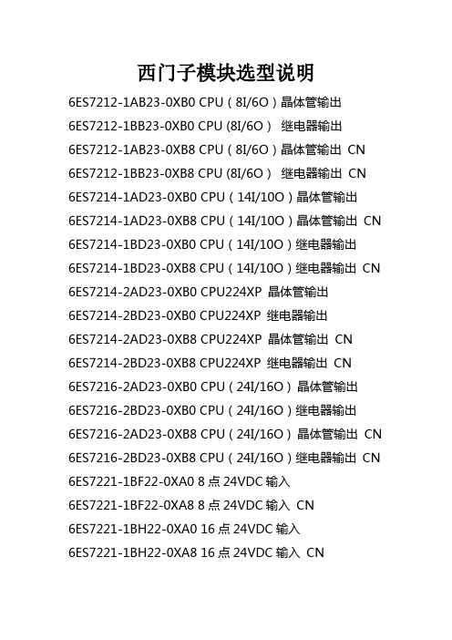
西门子模块选型说明6ES7212-1AB23-0XB0 CPU(8I/6O)晶体管输出6ES7212-1BB23-0XB0 CPU (8I/6O)继电器输出6ES7212-1AB23-0XB8 CPU(8I/6O)晶体管输出 CN6ES7212-1BB23-0XB8 CPU (8I/6O)继电器输出 CN6ES7214-1AD23-0XB0 CPU(14I/10O)晶体管输出6ES7214-1AD23-0XB8 CPU(14I/10O)晶体管输出 CN6ES7214-1BD23-0XB0 CPU(14I/10O)继电器输出6ES7214-1BD23-0XB8 CPU(14I/10O)继电器输出 CN 6ES7214-2AD23-0XB0 CPU224XP 晶体管输出6ES7214-2BD23-0XB0 CPU224XP 继电器输出6ES7214-2AD23-0XB8 CPU224XP 晶体管输出 CN6ES7214-2BD23-0XB8 CPU224XP 继电器输出 CN6ES7216-2AD23-0XB0 CPU ( 24I/16O ) 晶体管输出6ES7216-2BD23-0XB0 CPU(24I/16O)继电器输出6ES7216-2AD23-0XB8 CPU ( 24I/16O ) 晶体管输出 CN 6ES7216-2BD23-0XB8 CPU(24I/16O)继电器输出 CN 6ES7221-1BF22-0XA0 8点24VDC输入6ES7221-1BF22-0XA8 8点24VDC输入 CN6ES7221-1BH22-0XA0 16点24VDC输入6ES7221-1BH22-0XA8 16点24VDC输入 CN6ES7222-1HF22-0XA0 8点继电器输出6ES7222-1HF22-0XA8 8点继电器输出 CN6ES7222-1BF22-0XA0 8点24VDC输出6ES7222-1BF22-0XA8 8点24VDC输出 CN6ES7223-1PH22-0XA0 8入8出模块继电器输出6ES7223-1PH22-0XA8 8入8出模块继电器输出 CN 6ES7223-1PL22-0XA0 16入16出模块继电器输出6ES7223-1PL22-0XA8 16入16出模块继电器输出 CN 6ES7223-1HF22-0XA0 4入4出模块继电器输出6ES7223-1HF22-0XA8 4入4出模块继电器输出 CN6ES7223-1BF22-0XA0 4入4出24VDC6ES7223-1BF22-0XA8 4入4出24VDC CN6ES7223-1BH22-0XA0 8入8出24VDC6ES7223-1BH22-0XA8 8入8出24VDC CN6ES7223-1BL22-0XA0 16入16出24VDC6ES7223-1BL22-0XA8 16入16出24VDC CN6ES7231-0HC22-0XA0 4入模拟量模块6ES7231-0HC22-0XA8 4入模拟量模块 CN6ES7235-0KD22-0XA0 4入1出模拟量模块6ES7235-0KD22-0XA8 4入1出模拟量模块 CN6ES7232-0HB22-0XA0 2出模拟量模块6ES7232-0HB22-0XA8 2出模拟量模块 CN6ES7277-0AA22-0XA0 PROFIBUS-DP模块6ES7272-0AA30-0YA0 TD 200显示设定单元6ES7901-3CB30-0XA0 计算机编程电缆及软件6ES7291-8GF23-0XA0 EEPROM 64K6ES7291-8BA20-0XA0 电池6ES7290-6AA20-0XA0 扩展转接电缆 0.8米6ES7231-7PD22-0XA0 4路热电耦模块6ES7231-7PD22-0XA8 4路热电耦模块 CN 6ES7231-7PB22-0XA0 2路热电阻模块6ES7231-7PB22-0XA8 2路热电阻模块 CN6GK7243-1EX00-0XE0 以太网通讯卡。
西门子变送器选型说明

西门子变送器选型说明压力变送器(Hart )7MF4033-1AA10-2AC0-ZA02+Y01+Y15{Y01: }{Y15: }SITRANS P DS III ,HART, 4-20 MA 用于测量压力1 测量元件冲液:硅油测量元件清洗:标准A 量程: 0.83 (25)kPa (0.12 ... 3.6psi), 最大允许测量压力 4 BARB 量程:0,01 ... 1bar g (0.15 ...14.5psi),最大允许测量压力4barC 量程:0,04 ... 4 BARG(0.58 ... 58PSI G),最大允许测量压力 10BARD 量程:0,16 ... 16 barg(2.32 ... 232psi g),最大允许测量压力 32barE 量程:0,63 ... 63 barg(9.14 ... 914psi g),最大允许测量压力100 barF 量程:1,6 ...160 barg(23.2 ... 2320psi g),最大允许测量压力250 barG量程:4,0 ...400 barg(58.0 ... 5802psi g),最大允许测量压力600 barA 密封膜片不锈钢过程连接不锈钢1 过程连接: 阴螺纹1/2-14 NPT0 铸铝外壳2 默认英文名牌A 无防爆UnrestrictedC 电气连接/电缆入口: CABLE GLAND1/2-14 NPT0 无液晶数字显示A02不锈钢支架Y0 1 量程 (直行程特征 ) 文字说明:Y01:...TO ...MBAR,KPA,MP A,...Y1 5 不锈钢铭牌 (测量点描述) 最多16个字符, 文本说明绝压变送器(Hart )7MF4233-1FA10-2AC0-ZA02+Y01+Y15{Y01: }{Y15: }SITRANS P DS III ,HART, 4-20 MA 用于测量绝压1 测量元件冲液:硅油测量元件清洗:标准F 量程 : 43 TO 1300MBAR A (0.62 TO18.9 PSI A), 最大允许测量压力10BARH 量程 :30 bara (435psia), 最大允许测量压Unrestricted力 100bar A 密封膜片不锈钢过程连接不锈钢1 过程连接: 阴螺纹1/2-14 NPT0 铸铝外壳2 默认英文名牌A 无防爆C 电气连接/电缆入口: CABLE GLAND1/2-14 NPT0 无液晶数字显示A02不锈钢支架Y0 1 量程 (直行程特征 ) 文字说明:Y01:...TO ...MBAR,KPA,MP A,...Y1 5 不锈钢铭牌 (测量点描述) 最多16个字符, 文本说明差压变送器(Hart 7MF4433-1BA22-2AC0-ZA02+A40+Y01+Y15{Y01: }1 SITRANS P DS III,HART, 4-20 MA 用于测量差压和流量,Unrestricted){Y15: } PN 32/1601 测量元件冲液:硅油测量元件清洗:标准B 量程: PN 32 (MWP464 PSI): 20 MBAR(8.03 INH2O), 最大静压32 BAR C 量程:PN 160(MWP2320psi):60mbar(24.09inH2O), 最大静压160barD 量程:PN 160(MWP2320psi):250mbar(100.4inH2O),最大静压160barE 量程:PN 160(MWP2320psi):600mbar(240.9inH2O),最大静压160barG 量程:PN 160(MWP2320psi): 5bar(2008inH2O),最大静压 160barH 量程:PN 160(MWP2320psi):30 bar(435psi),最大静压160barA 密封膜片不锈钢过程连接不锈钢2 过程连接: : 1/4-18NPT 安装螺钉7/16-20 UNF2 铸铝外壳;过程法兰螺钉:不锈钢2 默认英文名牌A 无防爆C 电气连接/电缆入Unrestricted口: 1/2-14 NPT 0 无液晶数字显示表头A02不锈钢支架A4 0 排汽排液阀(1/4-18 NPT) WITH VALVE IN MATERIAL OF PROCESS FLANGEY0 1 量程 (直行程特征 ) 文字说明:, Y01:...TO ...MBAR,KPA,MP A,...Y1 5 不锈钢铭牌 (测量点描述) 最多16个字符, 文本说明差压变送器(Hart )7MF4533-1BA22-2AC0-ZA02+A40+Y01+Y15{Y01: }{Y15: }1 SITRANS P DS III,HART, 4-20 MA 用于测量差压和流量,PN 4201 测量元件冲液:硅油测量元件清洗:标准B 量程: PN 32 (MWP464 PSI): 20 MBAR(8.03 INH2O), 最C 量程:PN 160(MWPD 量程:PN 160(MWPE 量程:PN 160(MWPG 量程:PN 160(MWPH 量程:PN 160(MWPUnrestricted大静压32 BAR 2320psi):60mbar(24.09inH2O), 最大静压160bar 2320psi):250mbar(100.4inH2O),最大静压160bar2320psi):600mbar(240.9inH2O),最大静压160bar2320psi): 5bar(2008inH2O),最大静压 160bar2320psi):30 bar(435psi),最大静压160barA 密封膜片不锈钢过程连接不锈钢2 过程连接: : 1/4-18NPT 安装螺钉7/16-20 UNF2 铸铝外壳;过程法兰螺钉:不锈钢2 默认英文名牌A 无防爆C 电气连接/电缆入口: 1/2-14 NPT0 无液晶数字显示表头A02不锈钢支架UnrestrictedA4 0 排汽排液阀(1/4-18 NPT) WITH VALVE IN MATERIAL OF PROCESS FLANGEY0 1 量程 (直行程特征 ) 文字说明:, Y01:...TO ...MBAR,KPA,MP A,...Y1 5 不锈钢铭牌 (测量点描述) 最多16个字符, 文本说明UnrestrictedUnrestricted。
Haiwell(海为)PLC选型手册

创新的便利指令集:在分析吸收现有各种 PLC 指令的基础上,Haiwell PLC 推出许多功能强大的创新便利指令。如通讯指令 (COMM、MODR、MODW、HWRD、HWWR)、数据组合分散指令(BUNB、BUNW、WUNW、BDIB、WDIB、WDIW)、PID 控制(PID)、阀门控制(VC)、上下限报警(HAL、LAL)、范围变送(SC)、温度曲线(TTC)等,只需一条指令就能实现其他 PLC 需用多条指令来实现的功能,这些指令十分易于理解和使用,极大地提高了编程效率和程序运行速度。
强大的在线联机功能:可搜索出与 PC 上位机连接的所有 PLC,显示出所有在线 PLC 的运行状态、故障状态、RUN/STOP 开关
Haiwell
Haiwell PLC 选型手册
2 of 28
位置、硬件配置信息、通讯端口参数等详尽信息,可选择对任意一台 PLC 进行在线监控、程序上下载、固件升级、控制 PLC 运 行停止、调整 PLC 实时时钟、设置修改保护口令、修改通讯端口参数、修改看门狗时间和 PLC 站名称等。 在线监控调试功能:提供多达 10 页的元件监控表,可选择以十进制、十六进制、二进制、浮点数、字符方式显示数据,支持位 元件与寄存器元件混合监控并且同时显示元件注释。各种指令使用表格可导入到监控表中。 独有的实时曲线功能:可对任意寄存器元件进行实时曲线监控,方便过程控制调试。 人性化的输入方式:提供快捷键、拖放、点选等多种指令输入方式,对每个输入输出端子都提示其有效的元件或数值范围,可直 接输入,对一些组合数据(如通讯协议等)还可通过双击该指令以配置方式输入数据。 便利的注释功能:提供了元件注释、网络注释、指令注释、程序块注释、表格注释和项目注释功能,元件注释可通过在元件后跟 “//”直接输入(如:X0//电机启动),注释可选择下载到 PLC 中,方便日后上载程序的阅读或修改。 详尽的提示信息和在线帮助:提供 PLC 资源窗口、指令说明窗口等信息窗口,所有指令、硬件模块的详细说明均可在编程界面中 通过 F1 键打开在线帮助系统找到答案,即使首次使用 HaiwellHappy 编程软件也可轻松完成一个控制程序的编写工作。 方便的编辑功能:支持所有常规的编辑操作以及查找替换、指令上下移、网络上下移、程序项目之间的拷贝粘贴等。 硬件配置、子程序参数传递、局部元件、间接寻址、打印、预览、查错、CRC 计算、口令保护等
- 1、下载文档前请自行甄别文档内容的完整性,平台不提供额外的编辑、内容补充、找答案等附加服务。
- 2、"仅部分预览"的文档,不可在线预览部分如存在完整性等问题,可反馈申请退款(可完整预览的文档不适用该条件!)。
- 3、如文档侵犯您的权益,请联系客服反馈,我们会尽快为您处理(人工客服工作时间:9:00-18:30)。
S+B主令开关选型说明
S+B主令开关采用先进的模块化设计,可根据用户的不同使用要求将各个基本的功能模块相互叠加,即可组成一个完整的主令。
S+B主令开关型号的描述采用直接命名的方式将主令的各个功能模块按照先后的次序列出。
现在我们以一个常用的主令为例子介绍主令开关的命名方式和每个字母的含义:
例如:
VNSO 2 3 F N 14 KK V R Z 20.30+2×OGR8G
VNSO 代表主令开关的产品系列
S+B主令开关产品系列共计有4大类9种型号;MON, STO, ST1, CS1, NS3, VCSO,VNSO, NNSO, NS2。
划分主令型号主要依据主令的工作环境,触电电流和使用级别
2 3 两位数代表主令有前后左右2个工作方向,每位代表1个方向,其中前后有
2副触点组,左右有3副触点组,每副触点组包含有2个触点。
F 代表触点组的安装方式向下,向下安装便于接线,也可采用向上安装。
N 代表主令开关为左手使用,U为右手使用。
14 代表主令开关的手柄高度为14cm,常用的还有18cm和11cm。
KK 表示主令开关手柄的运动轨迹为十字,AK为万向(双向联动),SK是指一字型或其他特殊的手柄运动轨迹。
V 代表双向主令的触点呈水平V型90°布置,用户可根据联动台或控制柜的具体尺寸来灵活选择主令的布置方式。
常用的布置方式:单向:E,G,A型
双向:V,H,M,AA,EA,GG型
R 代表手柄自动回零,在作业频率高的设备上通常采用自动回零;如采用不会零的手柄,应该在主令中加装制动片(Friction disk)以避免手柄产生飘移。
Z 代表手柄的头部含有上提式机械联锁,也可以采用电气式浮点按钮和混合式。
常用的头部按钮方式:机械联锁式:Z, IZ
电气式浮点按钮:H, HD
混合式:HDSZ HDVSZ
20.30代表主令两个方向的触点闭合表,,S+B主令列出了
几十种常用的触点闭合表,用户也可以根据自己的需要制定出特别的闭合
表。
2×OGR8G 代表主令的两个方向各带有一个8位编码器,在直流和交流变频调速系统中,为使主令的输出更加平稳和线性,通常可在主令上加装编码器
OGR8G/B,电位计PQ或旋转变压器DGO。
在了解了主令开关的命名方式和每个字母的含义后,用户可以根据实际的需要选择所需的主令了。