数字音频矩阵 Audio Matrix 使用说明书
CME matrix x 音频矩阵系统x 说明书
Version 1.0Matrix X音頻矩陣系統 X用戶手冊 商標CME及Matrix X是中音公司的註冊商標。
其它的產品和品牌名稱是其各自公司的商標或註冊商標。
最終用戶保證中音公司對購買者的售後擔保聲明:當產品有缺陷,中音公司有責任維修或更換。
這個擔保不包括產品被誤用、濫用和修改而造成的缺陷。
除以上說明的,中音公司對產品不提供其它擔保。
該手冊不包含任何立場表達、購買誘導或其他暗示。
中音公司對由產品使用以外的原因造成的直接、間接、後繼或意外損壞不承擔責任。
在退回損壞的產品之前,您必須與中音公司或當地中音代理商聯繫獲取批准,將產品轉交給您所聯繫購買該產品時的中音代理商,委託該代理商來將產品返還給中音公司,產品必須帶有原始的或類似的保護包裝,並附上相應的產品購買憑證(收據、發票或其他)。
如果返還的產品被證明有缺陷,修好後或更換的產品將通過中音公司遞回給相應的代理商,並由該代理商轉交給您。
在購買後的十二個月內,中音公司對在正常的使用中出現的質量問題,提供免費保修,超過12個月,需要根據具體情況,付費維修。
FCC和CE規章警告這個設備符合FCC條例第15章的規定。
運行必須遵守以下兩個條件:(1)設備不能帶來有害的干擾;(2)設備必須接受任何收到的干擾,包括引起不理想運作的干擾。
警告:沒有經過承擔責任方的特別允許而對該設備的結構做出任何改變或修改將使使用者失去運行該設備的權利。
注意:設備已經經過檢測並符合FCC條款第15章的B級數字設備的限制。
這些限制是為了確保當設備在一個商業環境下運行時,對有害的干擾提供合理的保護。
設備會產生,使用和放射無線電波。
如果沒有按照使用說明書安裝和使用設備,它會發射出對無線通信有害的干擾。
在住宅中運行這個設備,將由可能帶來有害干擾,用戶需要負責消除這種干擾。
如果需要,可以向有經驗的無線電/電視技術員尋求更多的意見。
聯繫尋求技術支持,可以咨詢您所聯繫購買時的中音代理商或直接與中音公司聯繫。
音频矩阵说明
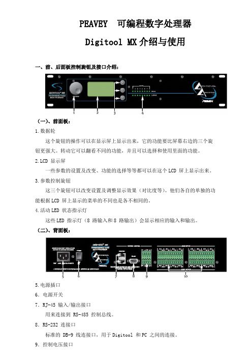
PEAVEY 可编程数字处理器Digitool MX介绍与使用一、前、后面板控制旋钮及接口介绍:(一)、前面板:1.数据轮这个旋钮的操作可以在显示屏上显示出来,它的功能要比屏幕右边的三个旋钮更强大。
转动它可以翻看不同的功能,并且可以选择和使用里面的功能。
2.LCD 显示屏一些参数的设置及改变、功能的选择等等都可以在这个LCD 屏上显示出来。
3.参数控制旋钮这三个旋钮可以改变设置及调整显示效果(对比度等)。
他们各自的单独的功能根据LCD 屏上显示的菜单的不同也是各不相同的。
4.活动LED 状态指示灯这些LED 指示灯(8 路输入和8 路输出)会显示相应的输入和输出。
(二)、背面板:5.电源插口6.电源开关7.RJ-45 输入/输出接口用来连接到 RS-485 控制总线。
8.RS-232 连接口标准的 DB-9 线连接口,用于Digitool 和PC 之间的连接。
9.控制电压接口用于连接外部 0 到10V 的直流电压控制信号。
10.输入和输出用于模拟信号的输入和输出。
二、导航显示屏:位于前面板显示屏可以显示导航菜单及内部的编辑操作等。
显示屏左边的大数据轮,控制显示屏上光标的移动。
(1)选择显示屏上的选项:数据轮除了可以移动光标外,还可以选择屏幕上的菜单。
(2)参数控制旋钮:在显示屏右边有 3 个参数控制旋钮。
它们转动的时候,显示屏右边的相对应的3 个小方框中的参数也会随之变化。
在Mix 菜单中他们控制的参数如图1 所示:(图1)(3)Mix(混合)菜单:从混合菜单中可以看到 8 个输出通道。
从图1 中可以看到混合菜单的组成以及可以调节的一些参数。
转动数据轮选择相应的输入或输出,其相应的数据也会在右边的小方框中显示出来。
屏幕上左边的8 个通道是输入通道,右面的是输出通道,图中箭头所指的是其中一个。
注意,图1 所示菜单中,每次只能显示一个输出混合。
(4)混合菜单控制旋钮:这三个旋钮在 Mix 菜单中分别控制的是输出电平、(输入到输出的)混合电平及主输出电平。
Meyer sound Matrix3 中文说明书
CueStation入门指导本文章将着重描写如何利用Matrix3多声道演出音频控制系统来制作一幕幕充满想像力的音频场景,简单的描述了Matrix3系统操作软件CueStation的基本操作。
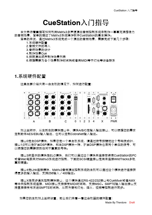
简单的来说,通过Matrix3系统完成一个演出的音频场景,需要完成下面几个步骤:1.系统硬件配置2.音频文件的导入3.音响场景的设计4.制作场景Cue5.按照演出顺序制作场景列表6.根据需要为各个场景制作时间码或者用MIDI等于灯光等设备联系1.系统硬件配置这里主要介绍只有一台主机的情况下,如何进行配置:如上图所示,从左到右的模块插口中,模块A/B/C是输入输出接口,可以根据您的需求定制数字AES/EBU输入输出,也可以定制CobraNet输入输出。
插口0是主DSP模块,如果您是一个单主机系统,请通过拨号按键把这个号码拨成01,插口1/2可以是扩展DSP模块,和主DSP模块一样,扩展DSP模块也有两个单位的拨号,可以根据您的需要拨到任何不重复的号码。
插口3所显示的模块是ELC模块,我们可以通过这个模块来连接安装有CueStation的PC 或者Mac电脑来对Matrix3系统进行控制,下面的SCSI硬盘接口是用来连接WildTracks多轨重放硬盘。
插口4是Link连接模块,Matrix3音频演出控制系统的主机可以通过这个模块进行连接获得更多的输入输出,支持256输入/400输出。
插口X是同步通讯控制模块接口,这个模块通过RS-422/232接口与CueMixer或者AMX 等中央控制系统连接,MIDI接口支持接受MIDI时间码,支持MSC。
SMPTE输入输出接口支持直接接受与发送SMPTE时间码,从而方便与灯光、烟火、视频等控制进行同步。
如果您的主机如上图所设置,那么我们来看一看这台机器的硬件配置:Slot A 话筒/线路模拟输入模块Slot B 模拟输出模块Slot C 模拟输出模块Slot 0 主DSP模块,号码为01Slot 1 扩展DSP模块,号码为11Slot 2 扩展DSP模块,号码为10Slot 3 ELC控制模块Slot 4 连接模块Slot X 同步通讯控制模块接着我们可以打开Matrix3主机,这时候我们需要注意主机的前面板,等待一段时间后,就会显示这个机器的MAC码和IP,我们需要把安装有CueStation的电脑设置到和Matrix3在同一个网段。
数字音频矩阵 Audio Matrix 使用说明书

序言本手册以全功能音频处理器矩阵的使用方法作为示例,并可作为其它型号处理器的使用参考。
本手册只作为用户操作指示,不作为维修服务用途。
本手册为本公司生产商版权所有,未经许可,任何单位或个人不得将本手册之部分或其全部内容作为商业用途。
目录安全操作指南 (2)一、产品概述 (3)1.1产品外观 (3)1.2功能介绍 (3)1.3产品参数 (3)二、前后面板接口说明 (5)2.1 前面板说明 (5)2.2 背板接口说明 (5)2.4 GPIO说明 (6)三、软件操作说明 (6)3.1网页控制和软件下载 (6)3.2 系统流程 (10)3.3 软件特色 (10)3.4 菜单栏和状态栏 (15)3.4.1文件 (15)3.4.2设备设置 (15)3.5 处理器模块 (22)3.5.1输入设置 (22)3.5.2扩展器 (23)3.5.3均衡器 (23)3.5.4压缩器 (25)3.5.5自动增益 (26)3.4.6自动混音器 (26)3.5.7反馈/回声/噪声消除 (28)3.5.8延时器 (30)3.5.9分频器 (30)3.5.10 限幅器 (31)3.5.11 输出设置 (32)附1:串口通信协议 (33)附2:GPIO说明 (34)安全操作指南为确保设备可靠使用及人员的安全,在安装、使用和维护时,请遵守以下事项:1.在设备安装时,应确保电源线中的地线接地良好,机箱接地点良好接地,请勿使用两芯插头。
确保设备的输入电源为100V-240V 、50/60Hz的交流电。
2.保持工作环境的良好通风,以便于设备在工作时所发的热量及时排出,以免温度过高而损坏设备。
3.在潮湿结露环境或长时间不使用时,应关闭设备总电源。
4.在下列操作之前一定要将设备的交流电源线从交流供电插座拔下:A.取下或重装设备的任何部件。
B.断开或重接设备的任何电器插头或连接。
5.设备内有交流高压部件,非专业人士未经许可,请勿擅自拆解设备,以免发生触电危险。
AVTRONSYS-矩阵使用手册

专业矩阵切换器该系列按键适用于8x8规模以下矩阵1) 指示灯COM: 串口通讯指示灯,当发送串口命令时该灯闪烁RUN: 运行指示灯,一直处于常亮状态说明设备运行正常2) 显示屏OUTPUT(输出通道号) 1 2 3 4 5 6 7 8INPUT(输入通道号) 1 2 3 4 5 6 7 83) 按键在前面板上的键盘::INPUT/OUTPUTINPUT/OUTPUT0 —9: 数字键,用于输出通道,设备地址和场景的选择。
ALL: 输入通道号+All,可将该输入切换到所有输出通道。
序号名称功能1 Audio 用于选择切换音频模式2 Video 用于选择切换视频模式3 AFV 用于选择切换音视频模式4 STO Store,用于存储场景5 REC Recall,用于恢复场景6 LOCK 锁定键盘或解除键盘锁定7 FUN 更换设备地址8 TAKE 确定操作4)设备地址的修改:“FUN”+“1-9”+TAKE5) 切换指令操作方法:“输出通道”+ “功能键”+“输入通道”+“TAKE”;6)“功能键”是指:AFV : 表示音视频信号同时切换,Video: 表示只切换视频信号或VGA信号,Audio: 表示只切换音频信号,* “输出通道”是指:要连接的下级设备当前所连接的通道,面板上的“0-9”号数字键。
* “输入通道”是指:要切换的信号源当前所连接的通道,面板上的“0-9”号数字键。
* “TAKE”是指:表示确认操作。
现在以8系列为例说明:例1:将第6路音视频输入信号切换到第8路通道输出,操作如下:“8” + A V + “6” + “TAKE”例2:将7路视频输入信号切换到第8路通道输出,操作如下:“8” + “Video” +“7” + “TAKE”例3:将第2路音视频输入信号切换到所有通道输出,操作如下:“ALL”+ “A V”+2”+ “TAKE”SA VE存储指令操作方法: 例如:将当前状态存储到4,操作如下:“STO” + “4” + “TAKE”RECALL调用指令操作方法:例如:将存储单元4的切换状态调用为当前状态,操作如下:“RECALL” + “4” + “TAKE”232串口接线说明矩阵上232串口使用的通用DB9接口,如下:2脚为TXD3脚为RXD5脚为GND与电脑直接用直通线连接即可。
音频矩阵说明

PEAVEY 可编程数字处理器Digitool MX介绍与使用一、前、后面板控制旋钮及接口介绍:(一)、前面板:1.数据轮这个旋钮的操作可以在显示屏上显示出来,它的功能要比屏幕右边的三个旋钮更强大。
转动它可以翻看不同的功能,并且可以选择和使用里面的功能。
显示屏一些参数的设置及改变、功能的选择等等都可以在这个LCD 屏上显示出来。
3.参数控制旋钮这三个旋钮可以改变设置及调整显示效果(对比度等)。
他们各自的单独的功能根据LCD 屏上显示的菜单的不同也是各不相同的。
4.活动LED 状态指示灯这些LED 指示灯(8 路输入和8 路输出)会显示相应的输入和输出。
(二)、背面板:5.电源插口6.电源开关7.RJ-45 输入/输出接口用来连接到RS-485 控制总线。
8.RS-232 连接口标准的DB-9 线连接口,用于Digitool 和PC 之间的连接。
9.控制电压接口用于连接外部0 到10V 的直流电压控制信号。
10.输入和输出用于模拟信号的输入和输出。
二、导航显示屏:位于前面板显示屏可以显示导航菜单及内部的编辑操作等。
显示屏左边的大数据轮,控制显示屏上光标的移动。
(1)选择显示屏上的选项:数据轮除了可以移动光标外,还可以选择屏幕上的菜单。
(2)参数控制旋钮:在显示屏右边有 3 个参数控制旋钮。
它们转动的时候,显示屏右边的相对应的3 个小方框中的参数也会随之变化。
在Mix 菜单中他们控制的参数如图1 所示:(图1)(3)Mix(混合)菜单:从混合菜单中可以看到8 个输出通道。
从图1 中可以看到混合菜单的组成以及可以调节的一些参数。
转动数据轮选择相应的输入或输出,其相应的数据也会在右边的小方框中显示出来。
屏幕上左边的8 个通道是输入通道,右面的是输出通道,图中箭头所指的是其中一个。
注意,图1 所示菜单中,每次只能显示一个输出混合。
(4)混合菜单控制旋钮:这三个旋钮在Mix 菜单中分别控制的是输出电平、(输入到输出的)混合电平及主输出电平。
FLX-MADI数字音频转换器用户手册说明书
ruUser's ManualTable of Contents1. QUICK REFERENCE (4)2. INTRODUCTION (5)2.1. Purpose (5)2.2. Box Contents (5)2.3. Conventions used in this manual (5)3. POSSIBLE SETUPS (6)3.1. Available AUX cards (6)3.2. Available FLX devices (7)3.3. FlexLink connection (7)4. AUDIO ROUTING (8)4.1. Modes and indication (8)4.2. Selecting the Route Mode (9)4.3. Remarks (9)5. CLOCK SETTINGS (10)5.1. Clock sources and indication (10)5.2. Selecting the Clock Source (10)6. ACCESSING INTERNALS (12)6.1. Opening the device (12)6.2. Inside view (12)6.3. Installing AUX cards (12)7. DIP SETTINGS (13)7.1. Base device config (DIP1..3) (13)7.2. AUX config (DIP4..6) (14)7.3. FlexLink channel mapping (DIP7..9) (15)8. SPECIAL OPERATING MODES (16)8.1. Version Display (16)8.2. LED Test (16)8.3. Interface Self-Test (16)8.4. Firmware update (17)9. SPECIFICATIONS (18)10. ACCESSORIES (18)10.1. Rack mount kits (18)10.2. Additional (redundant) power supply (18)11. APPENDIX (19)11.1. Warranty (19)11.2. Manufacturer contact (19)11.3. FCC Compliance (19)11.4. Recycling (20)FLX-MADI 11.5. Document Revision History (20)11.6. About this document (20)User's Manual1. QUICK REFERENCE➊Power switch and "power good" indicators.LEDs light up blue when power is available on the respective port.➋Mode indicators/selector. Long-press the "Select" button to change the audio routing between the interfaces. Wait four seconds to activate the selected mode.➌Clock indicators/selector. Long-press the "Select" button to change the clock source and sample-rate. Wait four seconds to activate the selected mode.➍MADI SFP port. Pre-installed 1310nm Multimode SFP, accepts any other SFPs Compatible to standard MADI optical (SC plugs) using an LC-to-SC adapter cable ➎MADI Coaxial port➏AUX slot. Accepts optional card for standalone use, or additional MADI channels ➐DIP switches, mostly to control output data format. See 7 . DIP Settings➑USB port (firmware update only, no audio)➒Redundant DC input ports➓FlexLink: optional connection to second flexiverter, or to multiverter.FLX-MADI2. INTRODUCTION2.1.PurposeThe FLX-MADI device is as digital audio converter, providing two built-in MADIinterfaces and a third one (or many other interfaces) with optional AUX cards. Itcan be used in different setups, depending on the user's needs:standalone, to convert between the built-in MADI ports (media converter),standalone, to convert between one of the built-in MADI ports and an additionalAUX card (MADI-to-anything),together with another flexiverter, connected via FlexLink (for up to 192x192channels),together with the multiverter, connected via FlexLink. This provides remotecontrol, channel-wise routing and SRC (Sample Rate Conversion).For a detailed description of possible configurations see 3 . Possible Setups.2.2.Box Contents1 FLX-MADI Converter1 HDMI cable 0.5m / 1.7 ft with locking screws1 Power supply1 Power cord (country specific)This manual2.3.Conventions used in this manualA button on the front is shown like this: Mode or ClockA LED is shown like this:◌ off / ⬤on / ❇ blinkingA section marked with an "information" icon indicatesa useful tip.User's Manual3. POSSIBLE SETUPSThe device can be used in three different setups, shown below:3.1.Available AUX cardsAt the time of writing (2021-11), the following AUX cards are available. More will come, please check www.appsys.ch for updates.FLX-MADIAUX-AVB116x16ch / 32x0ch / 0x32ch MILAN-approved AVBAUX-DAC18ch analog outputs (1xDB25)AUX-DANTE64x64ch DANTE network cardAUX-MADI-COAX64x64ch MADI for coaxial cable (BNC connectors)AUX-MADI-OPTO64x64ch MADI optical, SC connector (Multimode 125um 1310 nm)AUX-MADI-SFP64x64ch MADI for SFP (Small-Factor Pluggable) modulesAUX-WORDCLOCK BNC wordclock I/O3.2.Available FLX devicesAt the time of writing (2021-11), the following FLX devices are available. More willcome, please check www.appsys.ch for updates.3.3.FlexLink connectionThe FlexLink connection is designed to connect Flexiverters with each other, orwith the Multiverter. It provides:192x192 channels bi-directional transmission of 24-bit uncompressed audio(fully transparent to AES3 compatible metadata bits)Super-low link latency of 4 samples (ca. 83µs)Dedicated, high-quality reference clock signal with automatic configurationPower supply for connected devices (to reduce cabling), alternatively serves asredundancy scheme when both devices are powered: in case of power failure,both devices keep working from the remaining power supply.Uses standard HDMI cables (with locking screws), to provide easy fieldreplacement in case of defects.1Estimated availability: Q1/2022User's Manual4. AUDIO ROUTINGThe flexiverter can operate in various routing modes, allowing you to pass audiobetween the available interfaces (MADI SFP, MADI coaxial, AUX and FlexLink) inmany different ways. The LEDs in the "MODE" section indicate the involvedinterfaces.4.1.Modes and indication2All incoming data is also split (output) to FlexLink: MADI SFP is split to Lane 1 (ch1-64), MADI coaxial is split to Lane 2 (ch65-128) and AUX is split to Lane 3 (ch129-192). The split is not indicated on the LEDs for clarity but is always active.FLX-MADIseconds, the selected mode is applied automatically.4.2.Selecting the Route ModeLong-press the Mode button until the LEDs are blinking yellow.Current routing mode is shown by alternately yellow blinking LEDs, indicatingthe interfaces where the signal is passed between.Press the Mode button repeatedly to cycle between available modes, untilthe desired mode is shown.After four seconds without interaction, selection mode is terminated and thecurrent setting comes into effect.4.3.RemarksRouting between the selected interfaces is always bi-directional, meaning thataudio is passed between them both ways. A working bi-directional link shows⬤green for both interfaces. If the LED shows ⚪white, the correspondinginterface does only output data but no input on it has been detected. If the LEDshows ⬤ red, the interface is not connected, or the clock is invalid or missing.Channel-wise routing and splitting (crosspoint switch/matrix) between allchannels is possible when the flexiverter is connected to a multiverter. Routingis then done via the multiverter's web interface or via the command line.User's Manual5. CLOCK SETTINGS5.1.Clock sources and indicationThe flexiverter can be clocked from every interface (acting as clock slave), or canrun on its internal clock (acting as clock master).5.2.Selecting the Clock SourceLong-press the Clock button until the LEDs are blinking yellow.Current clock source/modes is shown by blinking LED(s).Press the Clock button repeatedly to cycle between the available clock sources. Depending on the source, you might need to select the desired sample rate (❇44.1 kHz or ❇48 kHz) and/or the appropriate multipliers (❇x2 /❇x4).After four seconds without interaction, clock setting is automatically terminated and the selected clock source comes into effect.6. ACCESSING INTERNALS6.1.Opening the deviceRequired: Torx T10 screwdriver.Power off the device and detach all cables to avoid short-circuit or damage.Detach the device from the rack-mount kit.Remove the four top screws and the top cover by pulling it upwards:6.2.Inside view➊Screws for AUX cover plate➋AUX card connector6.3.Installing AUX cardsRemove the screws holding the cover plate, and the blank cover plate ➊Insert the AUX card from inside, using the supplied cover plate.Make sure it is correctly fitted to the card connector➋Secure the card using two cover screws ➊The card has been installed correctly if you are able to select an audio routingmode involving AUX (long-press MODE button to enter Route Mode Selection).7. DIP SETTINGSFine-tuning of the flexiverter's built-in interface behavior and of the AUX card canbe achieved via DIP settings on the back side. Changing the DIP settings will come immediately into effect. Default setting: all switches up.7.1.Base device config (DIP1..3)The configuration below affects only the MADI outputs. The input format isautomatically detected, independent of the DIP switch settings.7.2.AUX config (DIP4..6)Many AUX card provide additional settings, which can be adjusted using theseswitches. The actual meaning depends on the type of AUX card installed:For cards not listed, refer to the manual of the respective card, or check for anewer version of this manual.3Applies to outputs only. Input format is always auto-detected, regardless of the switch setting7.3.FlexLink channel mapping (DIP7..9)The FlexLink interface can transmit 192x192 channels, organized in three laneswith 64 channels each. The channel assignment can be adjusted to meet the user's needs, particularly when the device is used in double-FLX configuration (to makesure that all interfaces and channels are mapped to the desired target on the peerFLX device.8. SPECIAL OPERATING MODESSpecial operating modes are accessible by holding down the Mode button while switching on the device. Press Mode again to switch to the next mode:Version Display ⇨ LED Test ⇨ Interface Self-Test ⇨ Normal operation 8.1.Version DisplayThe firmware version "X.Y" and the hardware version "Z" are shown on theLEDs on the front panel:- The number of ⬤pink LEDs lit indicate the major firmware number "X"- The number of ⬤orange LEDs lit indicate the minor firmware number "Y"- The number of ⬤green LEDs lit indicate the hardware version "Z"Example: One (1) ⬤pink LED and three (3) ⬤⬤⬤orange LEDs means"Firmware 1.3", zero green LEDs mean HW version 0.Blinking LEDs mean that the currently installed firmware is a "beta" version. Itis advised to upgrade to an official release version as soon as it is released.Press Mode again to proceed to LED test.8.2.LED TestAll LEDs on the front and on the back should show ⚪ white.Press Mode again to proceed to Interface Self-Test.8.3.Interface Self-TestAll built-in interfaces and the optional AUX card can be tested for correct operation by the user. This is done using the special self-test mode, in which the deviceoutputs a special random test pattern on all channels. This pattern is looped backvia an external cable into the corresponding inputs, where it is checked forconsistency.Self-test mode is indicated with "CLOCK"showing INT/48kHz in ⬤cyan color.The "MODE" LEDs indicate ⬤red (error/no connection) or ⬤green (loopbackdata received ok) for the respective interface.Connect the Output to the Input of the MADI SFP Port using an optical cable.Connect the Output to the Input of the MADI Coaxial Port using an coaxial(BNC) cable with 75 Ohms impedance.If an AUX card is installed, connect all output ports of the AUX card to therespective inputs using a loop-back cable. Note: NOT supported with AUX-ADC, AUX-AES67, AUX-AVB, AUX-DANTE.8.4.Firmware updateThe firmware can be updated from any Windows PC over the rear USB port.▶To update:Download the latest firmware from www.appsys.ch/FLX- MADIUnpack the firmware package FLX-MADI-Firmware_x.y.zipConnect your PC via USB to the flexiverterPower ON the deviceRun the FLX-MADI_Updater.bat file from the firmware package and follow theinstructions on the screen.Power cycle the device to effect the update.Thanks to the special design of the updater, it is virtuallyimpossible to damage ("brick") the device during update. Ifupdating fails or is interrupted, restart the procedure. You canalso can go back to any older firmware version at any time.9. SPECIFICATIONS10. ACCESSORIES10.1.Rack mount kitsFor integration in 19" racks, two kinds of rack mount kits / brackets are available:RM-FLX1: For mounting one FLX device into 1U 19" spaceRM-FLX2: For mounting two FLX devices into 1U 19" space10.2.Additional (redundant) power supplyPWR-FLX: Additional power supply to provide redundancy for single-FLXconfigurationsFlexLink Cable 0.5m. HDMI cable with locking screws11. APPENDIX11.1.WarrantyWe offer a full two (2) year warranty from the date of purchase. Within this period,we repair or exchange your device free of charge in case of any defect*. If youexperience any problems, please contact us first. We try hard to solve your problem as soon as possible, even after the warranty period.* Not covered by the warranty are any damages resulting out of improper use,willful damage, normal wear-out (especially of the connectors) or connection withincompatible devices.11.2.Manufacturer contactAppsys ProAudioRolf Eichenseher Bullingerstr. 63 / BK241 CH-8004 Zürich Switzerland www.appsys.ch**************Phone: +41 43 537 28 51 Mobile: +41 76 747 07 4211.3.FCC ComplianceThis equipment has been tested and found to comply with the limits for a class Bdigital device, pursuant to part 15 of the FCC Rules. These limits are designed toprovide reasonable protection against harmful interference in a residentialinstallation. This equipment generates, uses and can radiate radio frequency energy and if not installed and used in accordance with the instructions, may causeharmful interference to radio communications. However, there is no guarantee thatinterference will not occur in a particular installation. If this equipment does causeharmful interference to radio or television reception, which can be determined byturning the equipment off and on, the user is encouraged to try to correct theinterference by one or more of the following measures:Reorient or relocate the receiving antennaIncrease the separation between the equipment and receiverConnect the equipment into an outlet on a circuit different from that to whichthe receiver is connectedConsult the dealer or an experienced radio/TV technician for helpFLX-MADI This equipment has been verified to comply with the limits for a class B computingdevice, pursuant to FCC Rules. In order to maintain compliance with FCCregulations, shielded cables must be used with this equipment. Operation with non-approved equipment or unshielded cables is likely to result in interference to radioand TV reception. The user is cautioned that changes and modifications made tothe equipment without the approval of manufacturer could void the user’s authorityto operate this equipment.11.4.RecyclingAccording to EU directive 2002/96/EU, electronic devices with acrossed-out dustbin may not be disposed into normal domesticwaste. Please return the products back for environment-friendlyrecycling, we'll refund you the shipping fees.11.5.Document Revision History1: Initial release11.6.About this documentAll trademarks mentioned in this document are property of the respective owners.All information provided here is subject to change without prior notice.Document Revision: 1 · 2021-11-29Copyright © 2021 Appsys ProAudio · Printed in SwitzerlandIDENT 9.00.16146.00User's ManualDeclaration of ConformityThe manufacturer:Appsys ProAudioRolf EichenseherBullingerstr. 63 BK 241CH-8004 ZürichSwitzerlanddeclares under sole responsibility that the products mentioned below:Flexiverter FLX-MADImeet the requirements of the following standards:EN 55024:2010EN 55032:2015 Class BEN 61000-3-2:2006/A1/A2:2009EN 61000-3-3:2009EN 61000-6-3:2007/A1:2011Therefore the product fulfills the demand of the following EC directives:73/23/EWG(Directive related to electrical equipment designed for use within certain voltage limits)89/336/EWG(Directive related to electromagnetic compatibility)The devices are marked accordingly.Zürich, 21.11.2021Rolf Eichenseher (CEO)。
Maize Studio 1.2 中文说明书
$
!"$ #$%&'
yw! •½¾ OPH¿À •½¾$ ƒ„~…$½Á‚€ÂÃ}Ä€Å$ $
MIDI输入输出接口可以打开您的标准MIDI输入输出设备(比如键盘,控制器)。注意:别忘了 打开电源。
电脑键盘(Keyboard):
这个设备将您的电脑键盘变成一个MIDI输入设备。可以选择通道和音阶变换。
钟表(Clock) :
!"#$%&'()*#+ ,-./012-34567 !898 :;<3=>?@ABCD !898 3=:E FGHIJ34-?KLMN& ! D !"#" :;OPQR<S3=-01$!"#"%&'()*'+%"(,C% ! TUVWIJXYZ[>L\]^7 !"#" 3=_`abIcdeC% ! fghiM !"#" 3=jklmn:E% 请按时吃饭。 ! 34nopq>FGrsC% LStuvFG>_5wTUVxyWv34C& &
Maize Studio
中文书说明书
本说明帮助用户了解什么是模块化现场音频制作 环境,以及如何利用Maize Studio作为现场音频 辅助软件,进行音乐播放和音频处理。
欢迎使用Maize Studio
Maize Studio 简介
Maize Studio是一款模块化的数字音频平台,您可以自己设计创建音频设备,并将其用虚拟的连线连接起 来,灵活的组成各种用途的音频系统。Maize Studio支持VST插件,更为您提供了十几种高效方便的内置设 备。Maize Studio以完全面向设备的理念构件,所有功能都是一个设备,随着各种设备的加入,Maize Studio的功能会越来越丰富。
矩阵 说明书
以下给你发个矩阵说明书安装、连接、设置、通电、指示灯警告:全中文矩阵系统不能擅自拆离前面板,如用户拆离,擅自连线会影响通讯及程序。
安装要由有资格的服务人员进行,并应当遵守相应规定。
必须避免无关人员不当引起故障。
并且维护人员要预先考虑,避免由于掉落物,外来人员破坏,建筑物振动或它相似原因引起故障发生。
如果您在安装使用过程中遇到疑问和故障时,可向技术服务中心咨询。
一、安装全中文矩阵系统是按EIA标准设计3U机箱结构。
为便于通风和维修时的方便,安装时机箱的背面与墙的最小距离应不小于1米,并且全中文矩阵系统与任何其它设备之间应保持有0.5米的间距,安装人员应当确保有适当的气流流过机箱,以提供足够的通风条件。
二、连接系统中所有的连接器均设置在各机箱的后面板上。
为保证全部连接的正常完成,应在系统中所有设备都未通电时进行。
后面板连接如下图:2.1视/音频输出的连接视频输出插座设置在机箱的后面板,即标有数字(CON1-20)的那些DB15连接器,插上视频排线(带8个BNC插头)的BNC插头,其上都标清了输出序号,可接监视器、录像机(VCR)或其他具有75Ω输入阻抗的视频设备。
如果视频输出需要环接多个设备,则可经使用系统的环接输出口进行。
连接如图:2.2视/音频输入的连接视频输入连接是指将外部的视频信号接至,即标有数字(CON1-20)的那些DB15连接器,插上视频排线(带8个BNC插头)的BNC插头,其上都标清了输入序号。
对于全中文矩阵系统,各视频输入均接有75Ω电阻。
最好使用较高档的视频电缆,并且应遵循制造厂推荐的直接传送信号的最大距离。
注意:当传送距离超过300米时,最好应选用视频放大器对图像进行补偿。
视频输入的连接(全中文矩阵系统)对全中文矩阵系统,各视频输入未接有75Ω电阻,如果摄像机输入信号不环接到其他外接的75Ω终端设备,则全中文矩阵系统机箱相应的环接口必须有75Ω输入电阻,否则会造成图像信号过强、发白、字符抖动等现象。
音频矩阵说明
PEAVEY 可编程数字处理器Digitool MX介绍与使用一、前、后面板控制旋钮及接口介绍:(一)、前面板:1.数据轮这个旋钮的操作可以在显示屏上显示出来,它的功能要比屏幕右边的三个旋钮更强大。
转动它可以翻看不同的功能,并且可以选择和使用里面的功能。
2.LCD 显示屏一些参数的设置及改变、功能的选择等等都可以在这个LCD 屏上显示出来。
3.参数控制旋钮这三个旋钮可以改变设置及调整显示效果(对比度等)。
他们各自的单独的功能根据LCD 屏上显示的菜单的不同也是各不相同的。
4.活动LED 状态指示灯这些LED 指示灯(8 路输入和8 路输出)会显示相应的输入和输出。
(二)、背面板:5.电源插口6.电源开关7.RJ-45 输入/输出接口用来连接到 RS-485 控制总线。
8.RS-232 连接口标准的 DB-9 线连接口,用于Digitool 和PC 之间的连接。
9.控制电压接口用于连接外部 0 到10V 的直流电压控制信号。
10.输入和输出用于模拟信号的输入和输出。
二、导航显示屏:位于前面板显示屏可以显示导航菜单及内部的编辑操作等。
显示屏左边的大数据轮,控制显示屏上光标的移动。
(1)选择显示屏上的选项:数据轮除了可以移动光标外,还可以选择屏幕上的菜单。
(2)参数控制旋钮:在显示屏右边有 3 个参数控制旋钮。
它们转动的时候,显示屏右边的相对应的3 个小方框中的参数也会随之变化。
在Mix 菜单中他们控制的参数如图1 所示:(图1)(3)Mix(混合)菜单:从混合菜单中可以看到 8 个输出通道。
从图1 中可以看到混合菜单的组成以及可以调节的一些参数。
转动数据轮选择相应的输入或输出,其相应的数据也会在右边的小方框中显示出来。
屏幕上左边的8 个通道是输入通道,右面的是输出通道,图中箭头所指的是其中一个。
注意,图1 所示菜单中,每次只能显示一个输出混合。
(4)混合菜单控制旋钮:这三个旋钮在 Mix 菜单中分别控制的是输出电平、(输入到输出的)混合电平及主输出电平。
- 1、下载文档前请自行甄别文档内容的完整性,平台不提供额外的编辑、内容补充、找答案等附加服务。
- 2、"仅部分预览"的文档,不可在线预览部分如存在完整性等问题,可反馈申请退款(可完整预览的文档不适用该条件!)。
- 3、如文档侵犯您的权益,请联系客服反馈,我们会尽快为您处理(人工客服工作时间:9:00-18:30)。
序言本手册以全功能音频处理器矩阵的使用方法作为示例,并可作为其它型号处理器的使用参考。
本手册只作为用户操作指示,不作为维修服务用途。
本手册为本公司生产商版权所有,未经许可,任何单位或个人不得将本手册之部分或其全部内容作为商业用途。
目录安全操作指南 (2)一、产品概述 (3)1.1产品外观 (3)1.2功能介绍 (3)1.3产品参数 (3)二、前后面板接口说明 (5)2.1 前面板说明 (5)2.2 背板接口说明 (5)2.4 GPIO说明 (6)三、软件操作说明 (6)3.1网页控制和软件下载 (6)3.2 系统流程 (10)3.3 软件特色 (10)3.4 菜单栏和状态栏 (15)3.4.1文件 (15)3.4.2设备设置 (15)3.5 处理器模块 (22)3.5.1输入设置 (22)3.5.2扩展器 (23)3.5.3均衡器 (23)3.5.4压缩器 (25)3.5.5自动增益 (26)3.4.6自动混音器 (26)3.5.7反馈/回声/噪声消除 (28)3.5.8延时器 (30)3.5.9分频器 (30)3.5.10 限幅器 (31)3.5.11 输出设置 (32)附1:串口通信协议 (33)附2:GPIO说明 (34)安全操作指南为确保设备可靠使用及人员的安全,在安装、使用和维护时,请遵守以下事项:1.在设备安装时,应确保电源线中的地线接地良好,机箱接地点良好接地,请勿使用两芯插头。
确保设备的输入电源为100V-240V 、50/60Hz的交流电。
2.保持工作环境的良好通风,以便于设备在工作时所发的热量及时排出,以免温度过高而损坏设备。
3.在潮湿结露环境或长时间不使用时,应关闭设备总电源。
4.在下列操作之前一定要将设备的交流电源线从交流供电插座拔下:A.取下或重装设备的任何部件。
B.断开或重接设备的任何电器插头或连接。
5.设备内有交流高压部件,非专业人士未经许可,请勿擅自拆解设备,以免发生触电危险。
更不要私自维修,以免加重设备的损坏程度。
6.不要将任何腐蚀性化学品或液体洒在设备上或其附近。
一、产品概述1.1产品外观1.2功能介绍本设备最大支持模拟通道16进16出和1路USB扩展录播通道,高品质的21级前置放大电路,DSP处理总线结构,内置反馈消除器、噪声消除器、回声消除器等多种功能,还原高品质声音,主要应用于各种大型场所,可以满足剧场、音乐厅、远程视频会议、体育场馆、教堂、会议中心、主题公园等公共扩声系统等多方面的应用需求。
其操作简单,性能强大:1、全面的矩阵混音功能,24bit/48KHz取样频率,高性能A/D D/A转换器和32-bit浮点DSP处理器。
2、高精度的输入灵敏度调节,共计21档,步长3dB,最大输入增益60dB。
3、高效的算法处理:AFC,AEC,ANS,AUTOMIXER,EQ,GATE,AGC等。
4、丰富的接口扩展:支持8通道自定义输入输出的GPIO,电平支持外部输入3.3~24V;USB接口支持录播功能;RS-485支持自动摄像跟踪功能,轻松实现视频会议;RS-232双向串行控制接口:可发送或接受控制,如视频矩阵、摄像机等设备。
5、支持多组场景预设,场景保存等多种功能,人性化的操作软件界面。
6、方便快捷的网页控制:内置网页控制端口,在Windows、Android、iOS等平台上皆可快速操作。
1.3产品参数最大输入数量16最大输出数量16232串口数量 1485串口数量 1GPIO数量8,可自由配置输入输出RJ45数量 1USB数量1,可支持录播最大模拟增益-60dB幻象供电48V输入输出量化48KHz/24bitA/D动态范围120dB输入共模抑制80 dB @ +24dBu @60Hz输入阻抗20kΩ balance,10kΩ unbalance 最大输入24dBuD/A动态范围120dB通道隔离度100dB频率响应20~20kHz (±0.25dB)总谐波失真(THD+N) ≤0.002% @1kHz,+4dBu输出阻抗100 Ω balance,50 unbalance 最大输出24dBu工作电源AC 110V/220V 50Hz/60Hz工作温度0~40℃二、前后面板接口说明2.1 前面板说明1●(1)PWR:电源指示灯,灯亮表示设备供电正常,否则供电异常;●(2)SYS:状态指示灯,灯闪标表示设备运行正常,否则设备故障;●(3)USB:支持录播功能;●(4)电源开关。
2.2 背板接口说明●(1)机箱接地点;●(2)POWER:220V交流电源输入接口;●(3)ETHERNET:10M/100M以太网接口,用于连接控制端(PC、路由器等);●(4)RESET:恢复出厂设置,长按5秒有效;●(5)RS232:支持中控命令和摄像跟踪,RX:接收数据,TX:发送数据,G:地线;●(6)RS485:支持摄像跟踪;●(7)GPIO:GPIO控制;●(8)OUTPUT:模拟输出;●(9)INPUT:模拟输入。
2.4 GPIO说明G:接地1~8:8个GPIO端口,2-8均可自由配置输入或输出,端口1只有输入功能。
V:GPIO默认电源输出脚(5V)。
设备GPIO的状态实时显示在软件主界面的状态栏中:端口输出:每个输出端口均为OC输出,默认参考电压5V,也可外接小于15V的参考电压,取默认参考电压时,7个输出端口最大输出总电流为200mA:端口输入:输入高电平最低2V,输入高电平最高VCC+0.7V;输入低电平最高0.3V.GPIO的使用分为两种:(一)输出:即是矩阵内部某个参数发生变化时(如静音),引起GPIO某个输出管脚的输出电平的发生变化,从而驱动外部电路。
音频矩阵内部变化 -〉 GPIO管脚电平变化 -〉驱动外部电路。
(二)输入:即是外部电路发生改变时导致GPIO某个输入管脚电平发生变化,从而触发矩阵的某个参数发生变化。
外部电路状态变化 -〉 GPIO管脚电平变化 -〉音频矩阵内部变化。
详细操作见附录2。
三、软件操作说明3.1网页控制和软件下载设备出厂默认IP地址为:192.168.0.200子网掩码:255.255.255.0。
请先在PC中添加该网段的地址,以便设备正常连接。
设备启动完成后,用网页浏览器访问地址“http://192.168.0.200/”Control:控制通道参数以及各个处理器的启用和关闭。
Scene :快速调用和保存设备场景。
Download:下载链接提供 .Net框架、PC端软件和RS232中控命令生成器的下载,其中PC端软件支持XP、Win7、Win8操作系统。
在安装软件前,请确保PC端已经安装Microsoft .Net Framework3.5或以上版本。
安装软件时,部分系统(如WIN8)会弹出提示:“用户账号控制信息”,请点击“确定”键,提升软件的权限。
软件完成安装后,打开运行,界面如下:1、菜单栏和工具栏:菜单栏包括各项功能菜单2、处理器参数控制区:可拖动或滚动鼠标显示隐藏部分,支持复制/粘贴功能。
3、流程控制区:音频数据流程图,可点击图标对每个处理的参数进行详细设置。
4、输入/输出通道快速控制区:显示每个通道的电平和增益,以及各个处理器的快速启用/关闭按钮,支持复制/粘贴功能。
5、设备列表和场景控制区:显示当前的场景以及当前在线的设备。
6、状态栏:显示当前的连接设备登录用户名、IP、GPIO状态、场景下载进度。
点击右下角的“搜索设备”按钮。
在设备列表中双击对应设备的IP,弹出身份验证框:输入用户名和密码(出厂用户名admin\密码123456),点击登陆,状态栏提示如下:场景下载完后即可操控设备。
3.2 系统流程信号处理流程图输入:测试信号/静音/扩展器/5段均衡/压缩器/自动增益标准配置输出:延时器/分频器/31段图示均衡器/限幅器/输出相反/静音高级配置(AFC)反馈消除器(AEC)反馈消除器(ANS)噪声消除器(AutoMixer)自动混音器3.3 软件特色打开软件,初始化界面如下图所示:流程图和处理器控制模块之间的切换:窗口2为处理器详细参数显示区域,窗口3为处理流程图以及快速打开和关闭处理器的快速通道。
双击窗口3中的处理器,可打开/关闭窗口2中对应的详细参数控制模块,如双击“输入/扩展器/输出”:如上图,“输入/扩展器/输出”按照的详细设置界面按照流程图中的顺序排列在窗口2中,同时窗口3中已经打开详细设置参数的处理器会在右上角显示已打开状态,用红色的勾表示;当选中的处理器为输出,窗口3中的处理器也会用红色框表示。
在详细设置框的上方标识区,显示当前控制的通道号,上图输入输出均显示通道为1的参数。
上图输入部分显示通道为8的参数控制,输出部分显示通道为6的参数控制。
当通道的名称修改后,详细参数控制模块的通道名称会跟着变化。
快速控制区域:窗口4为输入输出通道的快捷控制方式,每个通道的处理器都可以快速直通和启用。
如通道数量较多,超过可显示的区域,可左右拖动或滚动鼠标中间滚轮来移动通道;输入:1)上方编辑框显示通道名称,可修改;修改后,窗口2中的详细参数控制界面的标识区域会跟着变化。
2)M、P、E、Q、C、G表示对应的输入通道快捷操作方式:M选中表示静音Q选中表示启用和关闭均衡器P选中表示打开和关闭幻象供电C选中表示启用和关闭压缩器E选中表示启用和关闭扩展器G选中表示启用和关闭自动增益最左边的按钮表示快速控制所有输入通道对应功能的开启和关闭。
3)电平表显示当前输出通道的输入电平。
4)推子调节当前输出通道的数字增益。
5)电平表显示当前输入通道的输入电平,可左右拖动或滚动鼠标中间键来显示隐藏的通道;点击通道可切换上方的功能模块的通道参数。
输出:1)上方编辑框显示通道名称,可修改;修改后,窗口2种的详细参数控制界面的标识区域会跟着变化。
2)M、D、X、Q、L、V表示对应的输入通道快捷操作方式:M选中表示静音Q选中表示启用和关闭均衡器D选中表示启用和关闭延时器L选中表示启用和关闭限幅器X选中表示启用和关闭分频器V选中表示启用和关闭输出反相最右边的按钮表示快速控制所有输出通道对应功能的开启和关闭。
3)电平表显示当前输出通道的输出电平。
4)推子调节当前输出通道的数字增益。
5)电平表显示当前输出通道的输出电平,可左右拖动或滚动鼠标中间键来显示隐藏通道;点击通道可切换上方的功能模块的通道参数。
示例:点击输出部分的延时器的全部启用快速按钮,如下所示,所有输出通道的延时器全部启用。
设备列表区:控制区:可以选择隐藏或显示设备列表。
场景设置:仅在连接上设备的情况下生效,可以选择运行设备不同的场景。
保持场景:将当前运行参数保持到选中的场景。
设备列表:显示当前在线设备,点击下方的“搜索设备”可刷新设备列表。