No logical path specified for the converted data
BIOS出错英文提示信息大全
Drive A error 驱动器A错误System halt 系统挂起Keyboard controller error 键盘控制器错误Keyboard error or no keyboard present 键盘错误或者键盘不存在BIOS ROM checksum error BIOS ROM校验错误Single hardisk cable fail 当硬盘使用Cable选项时硬盘安装位置不正确FDD Controller Failure BIOS 软盘控制器错误HDD Controller Failure BIOS 硬盘控制器错误Driver Error 驱动器错误Cache Memory Bad, Do not Enable Cache 高速缓存Cache损坏,不能使用Error: Unable to control A20 line 错误提示:不能使用A20地址控制线Memory write/Read failure 内存读写失败Memory allocation error 内存定位错误CMOS Battery state Low CMOS没电了Keyboard interface error 键盘接口错误Hard disk drive failure 加载硬盘失败Hard disk not present 硬盘不存在Floppy disk(s) fail (40) 软盘驱动器加载失败,一般是数据线插反,电源线没有插接,CMOS内部软驱设置错误CMOS checksum error-efaults loaded. CMOS校验错误,装入缺省(默认)设置Detecting floppy drive A media... 检测软驱A的格式Drive media is : 1.44Mb1.2Mb 720Kb 360K 驱动器格式是1.44Mb、12Mb、720kb、360kb 的一种DISK BOOT FAILURE, INSERT SYSTEM DISK AND PRESS ENTER 磁盘引导失败,插入系统盘后按任意键继续Invalid partition table 无效的分区表Error loading operating system 不能装入引导系统Missing operating system 系统引导文件丢失Invalid system disk 无效的系统盘Disk I/O error, Replace the disk and press any key. 磁盘I/O错误,替换磁盘后按任意键,当C盘系统文件丢失或被破坏时出现。
IUCVLINKStatement

The USERID parameter is required. All other parameters are optional and have default values as described. The underlined portion of the parameter is the minimum abbreviation.
IUCV LINK Statement
IUCV LINK Statement
IUCV LINK Statement
Each IUCV link must be defined with a LINK statement. LINK statements must follow the related DRIVER statement. The following is an example of the IUCV LINK statement:
PSTATS={N | Y}
This optional parameter determines whether or not (Y or N) statistics are printed to DDPRINT when the statistics interval expires. The default value is PSTATS=Y. This parameter does not affect the STATS operator command. The PSTATS parameter can be modified with the ALTER operator command; the link may be open or closed.
informix安装及配置
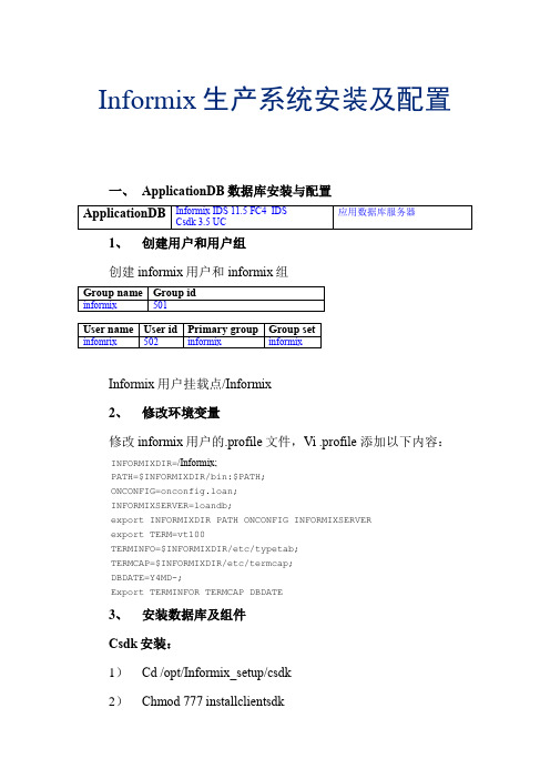
Informix生产系统安装及配置一、ApplicationDB数据库安装与配置1、创建用户和用户组创建informix用户和informix组Informix用户挂载点/Informix2、修改环境变量修改informix用户的.profile文件,Vi .profile 添加以下内容:INFORMIXDIR=/Informix;PATH=$INFORMIXDIR/bin:$PATH;ONCONFIG=onconfig.loan;INFORMIXSERVER=loandb;export INFORMIXDIR PATH ONCONFIG INFORMIXSERVERexport TERM=vt100TERMINFO=$INFORMIXDIR/etc/typetab;TERMCAP=$INFORMIXDIR/etc/termcap;DBDATE=Y4MD-;Export TERMINFOR TERMCAP DBDATE3、安装数据库及组件Csdk安装:1)Cd /opt/Informix_setup/csdk2)Chmod 777 installclientsdk3)./installclientsdk4)根据安装向导填写安装路径/informix,其他选项按默认值选择,之后开始安装IDS安装:1)Cd /opt/Informix_setup/server2)Chmod 777 installserver3)./installserver4)根据安装向导填写安装路径/informix,其他选项按默认值选择,之后开始安装4、更改磁盘设备信息属组及权限并链接设备文件将所有为AppliactionDB数据库创建的裸设备的字符型设备文件(c类型)的属组更改为informix:InformixCd /devChownInformix:Informixrloan* rflow* rtemp* rphy* rlog*将所有为AppliactionDB数据库创建的裸设备的字符型设备文件(c类型)的权限更改为660Chmod 660 rloan* rflow* rtemp* rphy* rlog*Su –InformixMkdir data将所有为AppliactionDB数据库创建的裸设备的字符型设备文件(c类型)软链接到该目录下,例如:Ln –s /dev/rloan_rootdbsloan_rootdbs链接所在目录:Loan_data_01:/Informix/data/loan_data/Loan_data_02:/Informix/data/loan_data/Loan_index_data:/Informix/data/loan_index/Flow_data_01:/Informix/data/flow_data/Flow_data_02:/Informix/data/flow_data/Flow_index_data:/Informix/data/flow_index/Tempdbs:/Informix/data/temp_data/Rootdbs:/Informix/data/Phy_loan_log:/Informix/data/Log_loan_log:/Informix/data/5、创建onconfig脚本Su –InformixCd etcCponconfig.stdonconfig.loanOnconfig参数修改:################################################################### # Licensed Material - Property Of IBM## "Restricted Materials of IBM"## IBM Informix Dynamic Server# Copyright IBM Corporation 1996, 2009. All rights reserved.## Title: onconfig.std# Description: IBM Informix Dynamic Server Configuration Parameters ## Important: $INFORMIXDIR now resolves to the environment# variable INFORMIXDIR. Replace the value of the INFORMIXDIR# environment variable only if the path you want is not under# $INFORMIXDIR.## For additional information on the parameters:# /infocenter/idshelp/v115/index.jsp####################################################################################################################################### Root Dbspace Configuration Parameters#################################################################### ROOTNAME - The root dbspace name to contain reserved pages and # internal tracking tables.# ROOTPATH - The path for the device containing the root dbspace # ROOTOFFSET - The offset, in KB, of the root dbspace into the# device. The offset is required for some raw devices. # ROOTSIZE - The size of the root dbspace, in KB. The value of # 200000 allows for a default user space of about# 100 MB and the default system space requirements.# MIRROR - Enable (1) or disable (0) mirroring# MIRRORPATH - The path for the device containing the mirrored# rootdbspace# MIRROROFFSET - The offset, in KB, into the mirrored device## Warning: Always verify ROOTPATH before performing# disk initialization (oninit -i or -iy) to# avoid disk corruption of another instance###################################################################ROOTNAME rootdbsROOTPATH $INFORMIXDIR/data/loan_rootdbs(修改到rootdbs所在目录)ROOTOFFSET 256 (偏移量256K)ROOTSIZE 4000000(大小4G)MIRROR 0MIRRORPATH $INFORMIXDIR/tmp/demo_on.root_mirrorMIRROROFFSET 0#################################################################### Physical Log Configuration Parameters#################################################################### PHYSFILE - The size, in KB, of the physical log on disk. # If RTO_SERVER_RESTART is enabled, the# suggested formula for the size of PHSYFILE# (up to about 1 GB) is:# PHYSFILE = Size of BUFFERS * 1.1# PLOG_OVERFLOW_PATH - The directory for extra physical log files# if the physical log overflows during recovery # or long transaction rollback# PHYSBUFF - The size of the physical log buffer, in KB###################################################################PHYSFILE 39000000PLOG_OVERFLOW_PATH $INFORMIXDIR/tmpPHYSBUFF 128################################################################### # Logical Log Configuration Parameters################################################################### # LOGFILES - The number of logical log files# LOGSIZE - The size of each logical log, in KB# DYNAMIC_LOGS - The type of dynamic log allocation.# Acceptable values are:# 2 Automatic. IDS adds a new logical log to the# root dbspace when necessary.# 1 Manual. IDS notifies the DBA to add new logical # logs when necessary.# 0 Disabled# LOGBUFF - The size of the logical log buffer, in KB###################################################################LOGFILES 250LOGSIZE 10000DYNAMIC_LOGS 2LOGBUFF 64################################################################### # Long Transaction Configuration Parameters################################################################### # If IDS cannot roll back a long transaction, the server hangs# until more disk space is available.## LTXHWM - The percentage of the logical logs that can be# filled before a transaction is determined to be a # long transaction and is rolled back# LTXEHWM - The percentage of the logical logs that have been # filled before the server suspends all other# transactions so that the long transaction being# rolled back has exclusive use of the logs## When dynamic logging is on, you can set higher values for# LTXHWM and LTXEHWM because the server can add new logical logs# during long transaction rollback. Set lower values to limit the # number of new logical logs added.## If dynamic logging is off, set LTXHWM and LTXEHWM to# lower values, such as 50 and 60 or lower, to prevent long# transaction rollback from hanging the server due to lack of# logical log space.## When using Enterprise Replication, set LTXEHWM to at least 30%# higher than LTXHWM to minimize log overruns.###################################################################LTXHWM 70LTXEHWM 80################################################################### # Server Message File Configuration Parameters################################################################### # MSGPATH - The path of the IDS message log file# CONSOLE - The path of the IDS console message file###################################################################MSGPATH $INFORMIXDIR/online_loan.logCONSOLE $INFORMIXDIR/tmp/online.con################################################################### # Tblspace Configuration Parameters################################################################### # TBLTBLFIRST - The first extent size, in KB, for the tblspace # tblspace. Must be in multiples of the page size. # TBLTBLNEXT - The next extent size, in KB, for the tblspace# tblspace. Must be in multiples of the page size. # The default setting for both is 0, which allows IDS to manage# extent sizes automatically.## TBLSPACE_STATS - Enables (1) or disables (0) IDS to maintain# tblspace statistics###################################################################TBLTBLFIRST 0TBLTBLNEXT 0TBLSPACE_STATS 1################################################################### # Temporary dbspace and sbspace Configuration Parameters################################################################### # DBSPACETEMP - The list of dbspaces used to store temporary# tables and other objects. Specify a colon# separated list of dbspaces that exist when the# server is started. If no dbspaces are specified,# or if all specified dbspaces are not valid,# temporary files are created in the /tmp directory# instead.# SBSPACETEMP - The list of sbspaces used to store temporary# tables for smart large objects. If no sbspace# is specified, temporary files are created in# a standard sbspace.###################################################################DBSPACETEMP tempdbsSBSPACETEMP################################################################### # Dbspace and sbspace Configuration Parameters################################################################### # SBSPACENAME - The default sbspace name where smart large objects # are stored if no sbspace is specified during# smart large object creation. Some DataBlade# modules store smart large objects in this# location.# SYSSBSPACENAME - The default sbspace for system statistics# collection. Otherwise, IDS stores statistics# in the sysdistrib system catalog table.# ONDBSPACEDOWN - Specifies how IDS behaves when it encounters a# dbspace that is offline. Acceptable values# are:# 0 Continue# 1 Stop# 2 Wait for DBA action###################################################################SBSPACENAMESYSSBSPACENAMEONDBSPACEDOWN 2################################################################### # System Configuration Parameters################################################################### # SERVERNUM - The unique ID for the IDS instance. Acceptable # values are 0 through 255, inclusive.# DBSERVERNAME - The name of the default database server# DBSERVERALIASES - The list of up to 32 alternative dbservernames, # separated by commas###################################################################SERVERNUM 0DBSERVERNAME loandbDBSERVERALIASES loandbshm################################################################### # Network Configuration Parameters################################################################### # NETTYPE - The configuration of poll threads# for a specific protocol. The# format is:# NETTYPE <protocol>,<# poll threads> # ,<number of connections/thread># ,(NET|CPU)# You can include multiple NETTYPE# entries for multiple protocols.# LISTEN_TIMEOUT - The number of seconds that IDS# waits for a connection# MAX_INCOMPLETE_CONNECTIONS - The maximum number of incomplete# connections before IDS logs a Denial # of Service (DoS) error# FASTPOLL - Enables (1) or disables (0) fast# polling of your network, if your# operating system supports it.###################################################################NETTYPE s octcp,8,500,NET (网络协议用户4000)NETTYPE ipcshm,2,50,CPU (内存通道用户100)LISTEN_TIMEOUT 60MAX_INCOMPLETE_CONNECTIONS 1024FASTPOLL 1################################################################### # CPU-Related Configuration Parameters################################################################### # MULTIPROCESSOR - Specifies whether the computer has multiple # CPUs. Acceptable values are: 0 (single# processor), 1 (multiple processors or# multi-core chips)# VPCLASS cpu - Configures the CPU VPs. The format is:# VPCLASS cpu,num=<#>[,max=<#>][,aff=<#>]# [,noage]# VP_MEMORY_CACHE_KB - Specifies the amount of private memory# blocks of your CPU VP, in KB, that the# database server can access.# Acceptable values are:# 0 (disable)# 800 through 40% of the value of SHMTOTAL# SINGLE_CPU_VP - Optimizes performance if IDS runs with# only one CPU VP. Acceptable values are:# 0 multiple CPU VPs# Any nonzero value (optimize for one CPU VP) ###################################################################MULTIPROCESSOR 1VPCLASS cpu,num=8,noageVP_MEMORY_CACHE_KB 0SINGLE_CPU_VP 0################################################################### # AIO and Cleaner-Related Configuration Parameters################################################################### # VPCLASS aio - Configures the AIO VPs. The format is:# VPCLASS aio,num=<#>[,max=<#>][,aff=<#>][,noage] # CLEANERS - The number of page cleaner threads# AUTO_AIOVPS - Enables (1) or disables (0) automatic management # of AIO VPs# DIRECT_IO - Specifies whether direct I/O is used for cooked# files used for dbspace chunks.# Acceptable values are:# 0 Disable# 1 Enable direct I/O# 2 Enable concurrent I/O####################################################################VPCLASS aio,num=1CLEANERS 8AUTO_AIOVPS 1DIRECT_IO 0################################################################### # Lock-Related Configuration Parameters################################################################### # LOCKS - The initial number of locks when IDS starts. # Dynamic locking can add extra locks if needed. # DEF_TABLE_LOCKMODE - The default table lock mode for new tables.# Acceptable values are ROW and PAGE (default). ###################################################################LOCKS 1000000DEF_TABLE_LOCKMODE row################################################################### # Shared Memory Configuration Parameters################################################################### # RESIDENT - Controls whether shared memory is resident.# Acceptable values are:# 0 off (default)# 1 lock the resident segment only# n lock the resident segment and the next n-1# virtual segments, where n < 100# -1 lock all resident and virtual segments# SHMBASE - The shared memory base address; do not change# SHMVIRTSIZE - The initial size, in KB, of the virtual# segment of shared memory# SHMADD - The size, in KB, of additional virtual shared# memory segments# EXTSHMADD - The size, in KB, of each extension shared# memory segment# SHMTOTAL - The maximum amount of shared memory for IDS,# in KB. A 0 indicates no specific limit.# SHMVIRT_ALLOCSEG - Controls when IDS adds a memory segment and# the alarm level if the memory segment cannot# be added.# For the first field, acceptable values are:# - 0 Disabled# - A decimal number indicating the percentage# of memory used before a segment is added# - The number of KB remaining when a segment# is added# For the second field, specify an alarm level# from 1 (non-event) to 5 (fatal error).# SHMNOACCESS - A list of up to 10 memory address ranges# that IDS cannot use to attach shared memory.# Each address range is the start and end memory # address in hex format, separated by a hyphen. # Use a comma to separate each range in the list. ###################################################################RESIDENT 0SHMBASE 0x700000010000000SHMVIRTSIZE 32656SHMADD 8192EXTSHMADD 8192SHMTOTAL 0SHMVIRT_ALLOCSEG 0,3SHMNOACCESS################################################################### # Checkpoint and System Block Configuration Parameters################################################################### # CKPINTVL - Specifies how often, in seconds, IDS checks# if a checkpoint is needed. 0 indicates that# IDS does not check for checkpoints. Ignored # if RTO_SERVER_RESTART is set.# AUTO_CKPTS - Enables (1) or disables (0) monitoring of# critical resource to trigger checkpoints# more frequently if there is a chance that# transaction blocking might occur.# RTO_SERVER_RESTART - Specifies, in seconds, the Recovery Time# Objective for IDS restart after a server# failure. Acceptable values are 0 (off) and# any number from 60-1800, inclusive.# BLOCKTIMEOUT - Specifies the amount of time, in seconds,# for a system block.###################################################################CKPTINTVL 1800AUTO_CKPTS 1RTO_SERVER_RESTART 0BLOCKTIMEOUT 3600################################################################### # Transaction-Related Configuration Parameters################################################################### # TXTIMEOUT - The distributed transaction timeout, in seconds# DEADLOCK_TIMEOUT - The maximum time, in seconds, to wait for a# lock in a distributed transaction.# HETERO_COMMIT - Enables (1) or disables (0) heterogeneous# commits for a distributed transaction# involving an EGM gateway.###################################################################TXTIMEOUT 300DEADLOCK_TIMEOUT 60HETERO_COMMIT 0################################################################### # ontape Tape Device Configuration Parameters################################################################### # TAPEDEV - The tape device path for backups. To use standard# I/O instead of a device, set to stdio.# TAPEBLK - The tape block size, in KB, for backups# TAPESIZE - The maximum amount of data to put on one backup# tape. Acceptable values are 0 (unlimited) or any# positive integral multiple of TAPEBLK.###################################################################TAPEDEV /dev/nullTAPEBLK 32TAPESIZE 0################################################################### # ontapeLogial Log Tape Device Configuration Parameters################################################################### # LTAPEDEV - The tape device path for logical logs# LTAPEBLK - The tape block size, in KB, for backing up logical # logs# LTAPESIZE - The maximum amount of data to put on one logical# log tape. Acceptable values are 0 (unlimited) or any # positive integral multiple of LTAPEBLK.###################################################################LTAPEDEV /dev/nullLTAPEBLK 32LTAPESIZE 0################################################################### # Backup and Restore Configuration Parameters#################################################################### BAR_ACT_LOG - The ON-Bar activity log file location.# Do not use the /tmp directory. Use a# directory with restricted permissions.# BAR_DEBUG_LOG - The ON-Bar debug log file location.# Do not use the /tmp directory. Use a# directory with restricted permissions.# BAR_DEBUG - The debug level for ON-Bar. Acceptable# values are 0 (off) through 9 (high).# BAR_MAX_BACKUP - The number of backup threads used in a# backup. Acceptable values are 0 (unlimited)# or any positive integer.# BAR_RETRY - Specifies the number of time to retry a# backup or restore operation before reporting # a failure# BAR_NB_XPORT_COUNT - Specifies the number of data buffers that# eachonbar_d process uses to communicate# with the database server# BAR_XFER_BUF_SIZE - The size, in pages, of each data buffer.# Acceptable values are 1 through 15 for# 4 KB pages and 1 through 31 for 2 KB pages.# RESTARTABLE_RESTORE - Enables ON-Bar to continue a backup after a# failure. Acceptable values are OFF or ON.# BAR_PROGRESS_FREQ - Specifies, in minutes, how often progress# messages are placed in the ON-Bar activity# log. Acceptable values are: 0 (record only# completion messages) or 5 and above.# BAR_BSALIB_PATH - The shared library for ON-Bar and the# storage manager. The default value is# $INFORMIXDIR/lib/ibsad001 (with a# platform-specific file extension).# BACKUP_FILTER - Specifies the pathname of a filter program# to transform data during a backup, plus any# program options# RESTORE_FILTER - Specifies the pathname of a filter program# to transform data during a restore, plus any # program options# BAR_PERFORMANCE - Specifies the type of performance statistics# to report to the ON-Bar activity log for backup # and restore operations.# Acceptable values are:# 0 = Turn off performance monitoring (Default) # 1 = Display the time spent transferring data # between the IDS instance and the storage # manager# 2 = Display timestamps in microseconds# 3 = Display both timestamps and transfer # statistics###################################################################BAR_ACT_LOG $INFORMIXDIR/tmp/bar_act.logBAR_DEBUG_LOG $INFORMIXDIR/tmp/bar_dbug.logBAR_DEBUG 0BAR_MAX_BACKUP 0BAR_RETRY 1BAR_NB_XPORT_COUNT 20BAR_XFER_BUF_SIZE 31RESTARTABLE_RESTORE ONBAR_PROGRESS_FREQ 0BAR_BSALIB_PATHBACKUP_FILTERRESTORE_FILTERBAR_PERFORMANCE 0################################################################### # Informix Storage Manager (ISM) Configuration Parameters################################################################### # ISM_DATA_POOL - Specifies the name for the ISM data pool# ISM_LOG_POOL - Specifies the name for the ISM log pool###################################################################ISM_DATA_POOL ISMDataISM_LOG_POOL ISMLogs################################################################### # Data Dictionary Cache Configuration Parameters################################################################### # DD_HASHSIZE - The number of data dictionary pools. Set to any# positive integer; a prime number is recommended. # DD_HASHMAX - The number of entries per pool.# Set to any positive integer.###################################################################DD_HASHSIZE 31DD_HASHMAX 10################################################################### # Data Distribution Configuration Parameters#################################################################### DS_HASHSIZE - The number of data Ddstribution pools.# Set to any positive integer; a prime number is# recommended.# DS_POOLSIZE - The maximum number of entries in the data# distribution cache. Set to any positive integer.###################################################################DS_HASHSIZE 31DS_POOLSIZE 127################################################################### User Defined Routine (UDR) Cache Configuration Parameters################################################################### PC_HASHSIZE - The number of UDR pools. Set to any# positive integer; a prime number is recommended.# PC_POOLSIZE - The maximum number of entries in the# UDR cache. Set to any positive integer.###################################################################PC_HASHSIZE 31PC_POOLSIZE 127#################################################################### SQL Statement Cache Configuration Parameters#################################################################### STMT_CACHE - Controls SQL statement caching. Acceptable# values are:# 0 Disabled# 1 Enabled at the session level# 2 All statements are cached# STMT_CACHE_HITS - The number of times an SQL statement must be# executed before becoming fully cached.# 0 indicates that all statements are# fully cached the first time.# STMT_CACHE_SIZE - The size, in KB, of the SQL statement cache# STMT_CACHE_NOLIMIT - Controls additional memory consumption.# Acceptable values are:# 0 Limit memory to STMT_CACHE_SIZE# 1 Obtain as much memory, temporarily, as needed # STMT_CACHE_NUMPOOL - The number of pools for the SQL statement# cache. Acceptable value is a positive# integer between 1 and 256, inclusive.###################################################################STMT_CACHE 0STMT_CACHE_HITS 0STMT_CACHE_SIZE 512STMT_CACHE_NOLIMIT 0STMT_CACHE_NUMPOOL 1################################################################### # Operating System Session-Related Configuration Parameters################################################################### # USEOSTIME - The precision of SQL statement timing.# Accepted values are 0 (precision to seconds)# and 1 (precision to subseconds). Subsecond# precision can degrade performance.# STACKSIZE - The size, in KB, for a session stack# ALLOW_NEWLINE - Controls whether embedded new line characters # in string literals are allowed in SQL# statements. Acceptable values are 1 (allowed) # and any number other than 1 (not allowed).# USELASTCOMMITTED - Controls the committed read isolation level.# Acceptable values are:# - NONE Waits on a lock# - DIRTY READ Uses the last committed value in # place of a dirty read# - COMMITTED READ Uses the last committed value # in place of a committed read# - ALL Uses the last committed value in place # of all isolation levels that support the last # committed option###################################################################USEOSTIME 0STACKSIZE 64ALLOW_NEWLINE 0USELASTCOMMITTED NONE################################################################### # Index Related Configuration Parameters################################################################### # FILLFACTOR - The percentage of index page fullness# MAX_FILL_DATA_PAGES - Enables (1) or disables (0) filling data# pages that have variable length rows as# full as possible# BTSCANNER - Specifies the configuration settings for all # btscanner threads. The format is:# BTSCANNER num=<#>,threshold=<#>,rangesize=<#>, # alice=(0-12),compression=[low|med|high|default] # ONLIDX_MAXMEM - The amount of memory, in KB, allocated for# the pre-image pool and updator log pool for# each partition.###################################################################FILLFACTOR 90MAX_FILL_DATA_PAGES 0BTSCANNER num=1,threshold=5000,rangesize=-1,alice=6,compression=default ONLIDX_MAXMEM 5120#################################################################### Parallel Database Query (PDQ) Configuration Parameters#################################################################### MAX_PDQPRIORITY - The maximum amount of resources, as a# percentage, that PDQ can allocate to any# one decision support query# DS_MAX_QUERIES - The maximum number of concurrent decision# support queries# DS_TOTAL_MEMORY - The maximum amount, in KB, of decision# support query memory# DS_MAX_SCANS - The maximum number of concurrent decision# support scans# DS_NONPDQ_QUERY_MEM - The amount of non-PDQ query memory, in KB.# Acceptable values are 128 to 25% of# DS_TOTAL_MEMORY.# DATASKIP - Specifies whether to skip dbspaces when# processing a query. Acceptable values are:# - ALL Skip all unavailable fragments# - ON <dbspace1><dbspace2>... Skip listed# dbspaces# - OFF Do not skip dbspaces (default)###################################################################MAX_PDQPRIORITY 100DS_MAX_QUERIESDS_TOTAL_MEMORYDS_MAX_SCANS 1048576DS_NONPDQ_QUERY_MEM 128DATASKIP#################################################################### Optimizer Configuration Parameters# OPTCOMPIND - Controls how the optimizer determines the best# query path. Acceptable values are:# 0 Nested loop joins are preferred# 1 If isolation level is repeatable read,# works the same as 0, otherwise works same as 2# 2 Optimizer decisions are based on cost only# DIRECTIVES - Specifies whether optimizer directives are# enabled (1) or disabled (0). Default is 1.# EXT_DIRECTIVES - Controls the use of external SQL directives.# Acceptable values are:# 0 Disabled# 1 Enabled if the IFX_EXTDIRECTIVES environment# variable is enabled# 2 Enabled even if the IFX_EXTDIRECTIVES# environment is not set# OPT_GOAL - Controls how the optimizer should optimize for# fastest retrieval. Acceptable values are:# -1 All rows in a query# 0 The first rows in a query# IFX_FOLDVIEW - Enables (1) or disables (0) folding views that# have multiple tables or a UNION ALL clause.# Disabled by default.# AUTO_REPREPARE - Enables (1) or disables (0) automatically# re-optimizing stored procedures and re-preparing# prepared statements when tables that are referenced # by them change. Minimizes the occurrence of the# -710 error.####################################################################OPTCOMPIND 2DIRECTIVES 1EXT_DIRECTIVES 0OPT_GOAL -1IFX_FOLDVIEW 0AUTO_REPREPARE 1#################################################################### Read-ahead Configuration Parameters####################################################################RA_PAGES - The number of pages, as a positive integer, to# attempt to read ahead#RA_THRESHOLD - The number of pages, as a postive integer, left# before the next read-ahead group。
RTL验证工具:VCS简介

+librescan Search from beginning of library list for all undefined Verilog modules. +notimingchecks Specifies no timing simulation (used for parsing only) +nospecify Specifies no path delays (used for VCS 数字逻辑仿真器和 VCS MX 混合 HDL 语言仿真器都是 Synopsys 的智能 RTL 验证解决方
案的基石。VCS 是业界领先的仿真器,支持本征断言(native assertion)描述、自动测试平台 生成技术(testbench)、以及代码和断言覆盖引擎,确保智能化验证的实现。VCS 中本征代码 支持 (Native)技术确保了设计验证的效率、性能和质量,并缩短了验证周期。VCS 中的本征 代码技术实现了在单一工具中,支持可验证性设计(DFV),及 覆盖率驱动和约束的随机激励 生成。其本征对断言的支持和所包含的丰富的断言检查工具库保证了设计人员能够方便地采用 DFV 技术来查找错误和提高验证质量。 此外,断言可以作为设计要求重复利用,在 Synopsys 的混合 RTL 规则验证产品 Magellan 中进行形式验证。 VCS 对专用集成电路(ASIC)生产商的建模和仿真签核(Sign-off)提供了支持。 VCS 对统一的设计和验证语言标准 SystemVerilog 提供支持。 SystemVerilog 增强了设计人员的 能力,加快了验证速度并提高了验证的质量。 对于要求在 RTL 环境中使用 SystemC 模型进行验证的设计团队,VCS 提供了支持 OSCI SystemC 的直接内核接口(DKI)和支持 System Studio 的直接内核接口(DKI)。 主要优点:
路径的英语单词

路径的英语单词导读:我根据大家的需要整理了一份关于《路径的英语单词》的内容,具体内容:路径是使用绘图工具创建的任意形状的曲线,用它可勾勒出物体的轮廓,所以也称之为轮廓线。
为了满足绘图的需要,路径又分为开放路径和封闭路径。
那么你知道是什么吗?下面来学习一下吧。
路径英语单... 路径是使用绘图工具创建的任意形状的曲线,用它可勾勒出物体的轮廓,所以也称之为轮廓线。
为了满足绘图的需要,路径又分为开放路径和封闭路径。
那么你知道是什么吗?下面来学习一下吧。
路径英语单词1:path路径英语单词2:route路径的英语例句:使虚拟路径成为相对路径将使该路径与应用程序无关。
Making a virtual path relative makes the path independent of the application.区域路径表达式可以是绝对路径,也可以是相对路径。
A location path can be absolute or relative.通道是连接到服务提供者的逻辑路径。
A channel is a logical path to service providers.必须指定一个或多个绝对路径名。
One or more absolute path names must be specified.该文件路径可以是相对路径或绝对路径。
The file path can be relative or absolute.输入的路径不是一个合法路径。
The path entered is not a legal path.相对路径是相对于当前项目目录的路径。
Relative paths are relative to the current project directory.此方法在路径中开始一个新子路径。
This method starts a new subpath in the path.以下是这类合作通常的演变路径:Here s the way it typically plays out:这里显示了9个模板路径选项。
软件测试期末试题(A卷)(英文)
软件学院级软件工程专业(2012-1)《软件测试》期末试题试卷(A)(考试形式:闭卷考试时间:2小时)考试作弊不授予学士学位方向:___________ 姓名:______ 学号:成绩:____________注意:答案一定要写在答卷中,写在本试题卷中不给分。
答题时注明各题题号,并在答题纸上写上姓名和学号。
本试卷要和答卷一起交回。
一、选择题(每题3分)1. How many statements are true?(1) You can perform dynamic black-box testing without a product specification orrequirements document.(2) If your product development is in a hurry, you can skip module testing and proceeddirectly to integration testing.(3) Threat modeling is an informal process done by the software testers to decide where bestto apply their tests for security vulnerabilities.Answers: A) 0 B) 1 C) 2 D) 32. How many statements are true?(1) Regression tests show if all defects have been resolved.(2) Regression tests are typically well-suited for test automation.(3) Regression tests should be performed in integration testing.Answers: A) 0 B) 1 C) 2 D) 33. How many statements are true?(1) All software has a user interface and therefore must be tested for usability.(2) Compatibility is a product feature and can have different levels of compliance.(3) Always design your black-box test cases first.Answers: A) 0 B) 1 C) 2 D) 34. How many statements are true?(1) With the big-bang model of software development, we have lower cost of testing.(2) An invasive(侵入性) tool is the best type because it operates closest to the softwarebeing tested.(3) A good tester relentlessly strives(坚持不懈地追求) for perfection.Answers: A) 0 B) 1 C) 2 D) 35. How many statements are true?(1) Software testing is mainly needed to improve the quality of the developer’s work.(2) Rigorous testing and fixing of defects found can help reduce the risk of problemsoccurring in an operational environment.(3) Rigorous testing is sometimes used to prove that all failures have been found.Answers: A) 0 B) 1 C) 2 D) 36. Which statement below BEST describes non-functional testing?A) The process of testing an integrated system to verify that it meets specifiedrequirements.B) The process of testing to determine the compliance of a system to coding standards.C) Testing without reference to the internal structure of a systemD) Testing system attributes, such as usability, reliability or maintainability.7. Which one of the review types below are the BEST fitted (most adequate) options to review source code.A) Formal reviewB) InspectionC) Peer reviewD) Technical Review8. One of the test goals for the project is to have 100% decision coverage. The following three test cases have been executed for the control flow graph shown below.Test case 1 covers path: A, B, D, E, G.Test case 2 covers path: A, B, D, E, F, G.Test case 3 covers path: A, C, F, C, F, C, F, G.AB CDE FGWhich of the following statements related to the decision coverage goal is correct?A) Decision D has not been tested completely.B) 100% decision coverage has been achieved.C) Decision E has not been tested completely.D) Decision F has not been tested completely.9. An e mployee’s bonus is to be calculated. It cannot become negative, but it can be calculated to zero. The bonus is based on the duration of the employment. An employee can be employed for less than or equal to 2 years, more than 2 years but less than 5 years, 5 to 10 years, or longer than 10 years. Depending on this period of employment, an employee will get eitherno bonus or a bonus of 10%, 25% or 35%.How many equivalence partitions are needed to test the calculation of the bonus?A) 3 B) 5 C) 2 D) 410. Which one of the following techniques is structure-based?A) Decision testing (Logical Coverage).B) Boundary value analysis.C) Equivalence partitioning.D) State transition testing.二、简答题(每题6分)1. Why would a software tester like the spiral or iterative model better than the others?2. Why is it impossible to test a program completely?3. Explain what's wrong with this specification statement: When the user selects the Compact Memory option, the program will compress the mailing list data as small as possible using a Huffman-sparse-matrix approach.4、If you're testing a program's ability to print to a printer, what generic test-to-fail test cases might be appropriate?5、What are the three basic states of a software bug's life cycle and the two common additional states?三、应用题(每题20分)1、White-box(1) Give a flow chart for the following source code.(2) Analyze the basis path for the flow chart, and list the basis test paths.(3) Design a suite of test cases to coverage all these paths.Program list: binary search - c (simple)1. /**2. #include <stdio.h>3. /**4. * binary search (simple)5. *6. * @param7. * arr pointer of array8. * @param9. * len length of array10. * @param11. * x target to search12. *13. * @return14. index of target in the array,return -1 if not found,15. */16. int bin_search(int *arr,int len,int x) {17. // indexs18. int start = 0,end = len-1,middle;19. while (end >= start) {20. middle = (start + end) >> 1;21. if (*(arr+middle)==x) {22. return middle;23. } else if(x < *(arr+middle)) {24. end = middle - 1;25. } else {26. start = middle + 1;27. }28. }29. // not found30. return -1;31. }2、Black-boxDesign functional test cases for the following QQ login form.(1)Design the effective and efficiency test cases.(2)Explain the reasons why we select these test cases.。
ADC0801LCN资料

ADC0801/ADC0802/ADC0803/ADC0804/ADC08058-Bit µP Compatible A/D ConvertersGeneral DescriptionThe ADC0801,ADC0802,ADC0803,ADC0804and ADC0805are CMOS 8-bit successive approximation A/D converters that use a differential potentiometric ladder —similar to the 256R products.These converters are designed to allow operation with the NSC800and INS8080A derivative control bus with TRI-STATE ®output latches di-rectly driving the data bus.These A/Ds appear like memory locations or I/O ports to the microprocessor and no interfac-ing logic is needed.Differential analog voltage inputs allow increasing the common-mode rejection and offsetting the analog zero input voltage value.In addition,the voltage reference input can be adjusted to allow encoding any smaller analog voltage span to the full 8bits of resolution.Featuresn Compatible with 8080µP derivatives —no interfacing logic needed -access time -135nsn Easy interface to all microprocessors,or operates “stand alone”n Differential analog voltage inputsn Logic inputs and outputs meet both MOS and TTL voltage level specificationsn Works with 2.5V (LM336)voltage reference n On-chip clock generatorn 0V to 5V analog input voltage range with single 5V supplyn No zero adjust requiredn 0.3"standard width 20-pin DIP packagen 20-pin molded chip carrier or small outline package n Operates ratiometrically or with 5V DC ,2.5V DC ,or analog span adjusted voltage referenceKey Specificationsn Resolution 8bitsn Total error±1⁄4LSB,±1⁄2LSB and ±1LSBn Conversion time100µsConnection DiagramOrdering InformationTEMP RANGE0˚C TO 70˚C 0˚C TO 70˚C−40˚C TO +85˚C ±1⁄4Bit Adjusted ADC0801LCN ERROR±1⁄2Bit Unadjusted ADC0802LCWM ADC0802LCN ±1⁄2Bit Adjusted ADC0803LCN±1Bit UnadjustedADC0804LCWM ADC0804LCN ADC0805LCN/ADC0804LCJPACKAGE OUTLINEM20B —SmallOutlineN20A —Molded DIPTRI-STATE ®is a registered trademark of National Semiconductor Corp.Z-80®is a registered trademark of Zilog Corp.ADC080XDual-In-Line and Small Outline (SO)PackagesDS005671-30See Ordering InformationNovember 1999ADC0801/ADC0802/ADC0803/ADC0804/ADC08058-Bit µP Compatible A/D Converters©1999National Semiconductor Corporation Typical ApplicationsError Specification (Includes Full-Scale,Zero Error,and Non-Linearity)Part Full-V REF /2=2.500V DC V REF /2=No Connection Number Scale (No Adjustments)(No Adjustments)AdjustedADC0801±1⁄4LSBADC0802±1⁄2LSBADC0803±1⁄2LSBADC0804±1LSBADC0805±1LSBDS005671-18080InterfaceDS005671-31A D C 0801/A D C 0802/A D C 0803/A D C 0804/A D C 0805 2Absolute Maximum Ratings(Notes1,2) If Military/Aerospace specified devices are required, please contact the National Semiconductor Sales Office/ Distributors for availability and specifications.Supply Voltage(V CC)(Note3) 6.5V VoltageLogic Control Inputs−0.3V to+18V At Other Input and Outputs−0.3V to(V CC+0.3V) Lead Temp.(Soldering,10seconds)Dual-In-Line Package(plastic)260˚C Dual-In-Line Package(ceramic)300˚C Surface Mount PackageVapor Phase(60seconds)215˚CInfrared(15seconds)220˚C Storage Temperature Range−65˚C to+150˚C Package Dissipation at T A=25˚C875mW ESD Susceptibility(Note10)800VOperating Ratings(Notes1,2)Temperature Range T MIN≤T A≤T MAX ADC0804LCJ−40˚C≤T A≤+85˚C ADC0801/02/03/05LCN−40˚C≤T A≤+85˚C ADC0804LCN0˚C≤T A≤+70˚C ADC0802/04LCWM0˚C≤T A≤+70˚C Range of V CC 4.5V DC to6.3V DCElectrical CharacteristicsThe following specifications apply for V CC=5V DC,T MIN≤T A≤T MAX and f CLK=640kHz unless otherwise specified.Parameter Conditions Min Typ Max UnitsADC0801:Total Adjusted Error(Note8)With Full-Scale Adj.±1⁄4LSB(See Section2.5.2)ADC0802:Total Unadjusted Error(Note8)V REF/2=2.500V DC±1⁄2LSBADC0803:Total Adjusted Error(Note8)With Full-Scale Adj.±1⁄2LSB(See Section2.5.2)ADC0804:Total Unadjusted Error(Note8)V REF/2=2.500V DC±1LSBADC0805:Total Unadjusted Error(Note8)V REF/2-No Connection±1LSBV REF/2Input Resistance(Pin9)ADC0801/02/03/05 2.58.0kΩADC0804(Note9)0.75 1.1kΩAnalog Input Voltage Range(Note4)V(+)or V(−)Gnd–0.05V CC+0.05V DCDC Common-Mode Error Over Analog Input Voltage±1/16±1⁄8LSBRangePower Supply Sensitivity V CC=5V DC±10%Over±1/16±1⁄8LSBAllowed V IN(+)and V IN(−)Voltage Range(Note4)AC Electrical CharacteristicsThe following specifications apply for V CC=5V DC and T MIN≤T A≤T MAX unless otherwise specified.Symbol Parameter Conditions Min Typ Max UnitsT C Conversion Time f CLK=640kHz(Note6)103114µsT C Conversion Time(Notes5,6)66731/f CLKf CLK Clock Frequency V CC=5V,(Note5)1006401460kHzClock Duty Cycle4060%CR Conversion Rate in Free-Running INTR tied to WR with87709708conv/s Mode CS=0V DC,f CLK=640kHzt W(WR)L Width of WR Input(Start Pulse Width)CS=0V DC(Note7)100nst ACC Access Time(Delay from Falling C L=100pF135200ns Edge of RD to Output Data Valid)t1H,t0H TRI-STATE Control(Delay C L=10pF,R L=10k125200ns from Rising Edge of RD to(See TRI-STATE TestHi-Z State)Circuits)t WI,t RI Delay from Falling Edge300450ns of WR or RD to Reset of INTRC IN Input Capacitance of Logic57.5pFControl InputsADC0801/ADC0802/ADC0803/ADC0804/ADC08053AC Electrical Characteristics(Continued)The following specifications apply for V CC =5V DC and T MIN ≤T A ≤T MAX unless otherwise specified.Symbol ParameterConditionsMinTyp Max Units C OUTTRI-STATE Output 57.5pFCapacitance (Data Buffers)CONTROL INPUTS [Note:CLK IN (Pin 4)is the input of a Schmitt trigger circuit and is therefore specified separately]V IN (1)Logical “1”Input Voltage V CC =5.25V DC 2.015V DC (Except Pin 4CLK IN)V IN (0)Logical “0”Input Voltage V CC =4.75V DC0.8V DC (Except Pin 4CLK IN)I IN (1)Logical “1”Input Current V IN =5V DC0.0051µA DC (All Inputs)I IN (0)Logical “0”Input Current V IN =0V DC−1−0.005µA DC(All Inputs)CLOCK IN AND CLOCK R V T +CLK IN (Pin 4)Positive Going 2.73.13.5V DC Threshold Voltage V T −CLK IN (Pin 4)Negative 1.51.82.1V DC Going Threshold Voltage V HCLK IN (Pin 4)Hysteresis 0.61.32.0V DC (V T +)−(V T −)V OUT (0)Logical “0”CLK R Output I O =360µA 0.4V DC VoltageV CC =4.75V DC V OUT (1)Logical “1”CLK R Output I O =−360µA 2.4V DCVoltageV CC =4.75V DCDATA OUTPUTS AND INTR V OUT (0)Logical “0”Output Voltage Data Outputs I OUT =1.6mA,V CC =4.75V DC 0.4V DC INTR OutputI OUT =1.0mA,V CC =4.75V DC 0.4V DC V OUT (1)Logical “1”Output Voltage I O =−360µA,V CC =4.75V DC 2.4V DC V OUT (1)Logical “1”Output Voltage I O =−10µA,V CC =4.75V DC 4.5V DC I OUT TRI-STATE Disabled Output V OUT =0V DC −3µA DC Leakage (All Data Buffers)V OUT =5V DC 3µA DC I SOURCE V OUT Short to Gnd,T A =25˚C 4.56mA DC I SINKV OUTShort to V CC ,T A =25˚C9.016mA DCPOWER SUPPLY I CCSupply Current (Includes f CLK =640kHz,Ladder Current)V REF /2=NC,T A =25˚C and CS =5VADC0801/02/03/04LCJ/05 1.1 1.8mA ADC0804LCN/LCWM1.92.5mANote 1:Absolute Maximum Ratings indicate limits beyond which damage to the device may occur.DC and AC electrical specifications do not apply when operating the device beyond its specified operating conditions.Note 2:All voltages are measured with respect to Gnd,unless otherwise specified.The separate A Gnd point should always be wired to the D Gnd.Note 3:A zener diode exists,internally,from V CC to Gnd and has a typical breakdown voltage of 7V DC .Note 4:For V IN (−)≥V IN (+)the digital output code will be 00000000.Two on-chip diodes are tied to each analog input (see block diagram)which will forward conduct for analog input voltages one diode drop below ground or one diode drop greater than the V CC supply.Be careful,during testing at low V CC levels (4.5V),as high level analog inputs (5V)can cause this input diode to conduct–especially at elevated temperatures,and cause errors for analog inputs near full-scale.The spec allows 50mV forward bias of either diode.This means that as long as the analog V IN does not exceed the supply voltage by more than 50mV,the output code will be correct.To achieve an absolute 0V DC to 5V DC input voltage range will therefore require a minimum supply voltage of 4.950V DC over temperature variations,initial tolerance and loading.Note 5:Accuracy is guaranteed at f CLK =640kHz.At higher clock frequencies accuracy can degrade.For lower clock frequencies,the duty cycle limits can be ex-tended so long as the minimum clock high time interval or minimum clock low time interval is no less than 275ns.Note 6:With an asynchronous start pulse,up to 8clock periods may be required before the internal clock phases are proper to start the conversion process.The start request is internally latched,see Figure 4and section 2.0.A D C 0801/A D C 0802/A D C 0803/A D C 0804/A D C 0805 4AC Electrical Characteristics(Continued)Note7:The CS input is assumed to bracket the WR strobe input and therefore timing is dependent on the WR pulse width.An arbitrarily wide pulse width will hold the converter in a reset mode and the start of conversion is initiated by the low to high transition of the WR pulse(see timing diagrams).Note8:None of these A/Ds requires a zero adjust(see section2.5.1).To obtain zero code at other analog input voltages see section2.5and Figure7.Note9:The V REF/2pin is the center point of a two-resistor divider connected from V CC to ground.In all versions of the ADC0801,ADC0802,ADC0803,and ADC0805,and in the ADC0804LCJ,each resistor is typically16kΩ.In all versions of the ADC0804except the ADC0804LCJ,each resistor is typically2.2kΩ. Note10:Human body model,100pF discharged through a1.5kΩresistor.Typical Performance CharacteristicsLogic Input Threshold Voltage vs.Supply VoltageDS005671-38Delay From Falling Edge ofRD to Output Data Validvs.Load CapacitanceDS005671-39CLK IN Schmitt Trip Levelsvs.Supply VoltageDS005671-40f CLK vs.Clock CapacitorDS005671-41Full-Scale Error vsConversion TimeDS005671-42Effect of Unadjusted Offset Errorvs.V REF/2VoltageDS005671-43Output Current vsTemperatureDS005671-44Power Supply Currentvs Temperature(Note9)DS005671-45Linearity Error at LowV REF/2VoltagesDS005671-46ADC0801/ADC0802/ADC0803/ADC0804/ADC08055TRI-STATE Test Circuits and WaveformsTiming Diagrams(All timing is measured from the 50%voltage points)t 1HDS005671-47t 1H ,C L =10pFDS005671-48t r =20nst 0H DS005671-49t 0H ,C L =10pFDS005671-50t r =20nsDS005671-51A D C 0801/A D C 0802/A D C 0803/A D C 0804/A D C 0805 6Timing Diagrams(All timing is measured from the 50%voltage points)(Continued)Typical ApplicationsOutput Enable and Reset with INTRDS005671-52Note:Read strobe must occur 8clock periods (8/f CLK )after assertion of interrupt to guarantee reset of INTR .6800InterfaceDS005671-53Ratiometeric with Full-Scale AdjustDS005671-54Note:before using caps at V IN or V REF /2,see section 2.3.2Input Bypass Capacitors.ADC0801/ADC0802/ADC0803/ADC0804/ADC08057Typical Applications(Continued)Absolute with a 2.500V ReferenceDS005671-55*For low power,see also LM385–2.5Absolute with a 5V ReferenceDS005671-56Zero-Shift and Span Adjust:2V ≤V IN ≤5V DS005671-57Span Adjust:0V ≤V IN ≤3VDS005671-58A D C 0801/A D C 0802/A D C 0803/A D C 0804/A D C 0805 8Typical Applications(Continued)Directly Converting a Low-Level SignalDS005671-59V REF /2=256mVA µP Interfaced ComparatorDS005671-60For:V IN (+)>V IN (−)Output =FF HEX For:V IN (+)<V IN (−)Output =00HEX1mV Resolution with µP Controlled RangeDS005671-61V REF /2=128mV 1LSB =1mVV DAC ≤V IN ≤(V DAC +256mV)0≤V DAC <2.5VADC0801/ADC0802/ADC0803/ADC0804/ADC08059Typical Applications(Continued)Digitizing a Current FlowDS005671-62Self-Clocking Multiple A/Ds DS005671-63*Use a large R value to reduce loading at CLK R output.External ClockingDS005671-64100kHz ≤f CLK ≤1460kHzA D C 0801/A D C 0802/A D C 0803/A D C 0804/A D C 0805 10Typical Applications(Continued)Self-Clocking in Free-Running ModeDS005671-65*After power-up,a momentary grounding of the WR input is needed to guarantee operation.µP Interface for Free-Running A/DDS005671-66Operating with “Automotive”Ratiometric Transducers DS005671-67*V IN (−)=0.15V CC15%of V CC ≤V XDR ≤85%of V CCRatiometric with V REF /2ForcedDS005671-68µP Compatible Differential-Input Comparator with Pre-Set V OS (with or without Hysteresis)DS005671-69*See Figure 5to select R valueDB7=“1”for V IN (+)>V IN (−)+(V REF /2)Omit circuitry within the dotted area if hysteresis is not neededADC0801/ADC0802/ADC0803/ADC0804/ADC080511Typical Applications(Continued)Handling ±10V Analog InputsDS005671-70*Beckman Instruments #694-3-R10K resistor arrayLow-Cost,µP Interfaced,Temperature-to-DigitalConverterDS005671-71µP Interfaced Temperature-to-Digital ConverterDS005671-72*Circuit values shown are for 0˚C ≤T A ≤+128˚C***Can calibrate each sensor to allow easy replacement,then A/D can be calibrated with a pre-set input voltage.A D C 0801/A D C 0802/A D C 0803/A D C 0804/A D C 0805 12Typical Applications(Continued)Handling±5V Analog InputsDS005671-33 *Beckman Instruments#694-3-R10K resistor array Read-Only InterfaceDS005671-34µP Interfaced Comparator with HysteresisDS005671-35Protecting the InputDS005671-9Diodes are1N914ADC0801/ADC0802/ADC0803/ADC0804/ADC080513Typical Applications(Continued)Analog Self-Test for a SystemDS005671-36A Low-Cost,3-Decade Logarithmic ConverterDS005671-37*LM389transistorsA,B,C,D =LM324A quad op ampA D C 0801/A D C 0802/A D C 0803/A D C 0804/A D C 0805 14Typical Applications(Continued)3-Decade Logarithmic A/D ConverterDS005671-73Noise Filtering the Analog Input DS005671-74f C =20HzUses Chebyshev implementation for steeper roll-off unity-gain,2nd order,low-pass filterAdding a separate filter for each channel increases system response time if an analog multiplexer is usedMultiplexing Differential InputsDS005671-75Output Buffers with A/D Data Enabled DS005671-76*A/D output data is updated 1CLK period prior to assertion of INTRIncreasing Bus Drive and/or Reducing Time on BusDS005671-77*Allows output data to set-up at falling edge of CSADC0801/ADC0802/ADC0803/ADC0804/ADC080515Typical Applications(Continued)Functional Description1.0UNDERSTANDING A/D ERROR SPECSA perfect A/D transfer characteristic (staircase waveform)is shown in Figure 1.The horizontal scale is analog input volt-age and the particular points labeled are in steps of 1LSB (19.53mV with 2.5V tied to the V REF /2pin).The digital out-put codes that correspond to these inputs are shown as D−1,D,and D+1.For the perfect A/D,not only will center-value(A−1,A,A+1,....)analog inputs produce the correct out-put digital codes,but also each riser (the transitions between adjacent output codes)will be located ±1⁄2LSB away from each center-value.As shown,the risers are ideal and have no width.Correct digital output codes will be provided for a range of analog input voltages that extend ±1⁄2LSB from the ideal center-values.Each tread (the range of analog input voltage that provides the same digital output code)is there-fore 1LSB wide.Sampling an AC Input SignalDS005671-78Note 11:Oversample whenever possible [keep fs >2f(−60)]to eliminate input frequency folding (aliasing)and to allow for the skirt response of the filter.Note 12:Consider the amplitude errors which are introduced within the passband of the filter.70%Power Savings by Clock GatingDS005671-79(Complete shutdown takes ≈30seconds.)Power Savings by A/D and V REF ShutdownDS005671-80*Use ADC0801,02,03or 05for lowest power consumption.Note:Logic inputs can be driven to V CC with A/D supply at zero volts.Buffer prevents data bus from overdriving output of A/D when in shutdown mode.A D C 0801/A D C 0802/A D C 0803/A D C 0804/A D C 080516Functional Description(Continued)Figure 2shows a worst case error plot for the ADC0801.All center-valued inputs are guaranteed to produce the correct output codes and the adjacent risers are guaranteed to be no closer to the center-value points than ±1⁄4LSB.In other words,if we apply an analog input equal to the center-value ±1⁄4LSB,we guarantee that the A/D will produce the correct digital code.The maximum range of the position of the code transition is indicated by the horizontal arrow and it is guar-anteed to be no more than 1⁄2LSB.The error curve of Figure 3shows a worst case error plot for the ADC0802.Here we guarantee that if we apply an analog input equal to the LSB analog voltage center-value the A/D will produce the correct digital code.Next to each transfer function is shown the corresponding error plot.Many people may be more familiar with error plots than transfer functions.The analog input voltage to the A/D is provided by either a linear ramp or by the discrete output steps of a high resolution DAC.Notice that the error is con-tinuously displayed and includes the quantization uncertainty of the A/D.For example the error at point 1of Figure 1is +1⁄2LSB because the digital code appeared 1⁄2LSB in advance of the center-value of the tread.The error plots always have a constant negative slope and the abrupt upside steps are always 1LSB in magnitude.Transfer FunctionDS005671-81Error PlotDS005671-82FIGURE 1.Clarifying the Error Specs of an A/D ConverterAccuracy =±0LSB:A Perfect A/DTransfer FunctionDS005671-83Error PlotDS005671-84FIGURE 2.Clarifying the Error Specs of an A/D ConverterAccuracy =±1⁄4LSBADC0801/ADC0802/ADC0803/ADC0804/ADC080517Functional Description(Continued)2.0FUNCTIONAL DESCRIPTIONThe ADC0801series contains a circuit equivalent of the 256R network.Analog switches are sequenced by succes-sive approximation logic to match the analog difference input voltage [V IN (+)−V IN (−)]to a corresponding tap on the R net-work.The most significant bit is tested first and after 8com-parisons (64clock cycles)a digital 8-bit binary code (11111111=full-scale)is transferred to an output latch and then an interrupt is asserted (INTR makes a high-to-low transi-tion).A conversion in process can be interrupted by issuing a second start command.The device may be operated in the free-running mode by connecting INTR to the WR input with CS =0.To ensure start-up under all possible conditions,an external WR pulse is required during the first power-up cycle.On the high-to-low transition of the WR input the internal SAR latches and the shift register stages are reset.As long as the CS input and WR input remain low,the A/D will remain in a reset state.Conversion will start from 1to 8clock peri-ods after at least one of these inputs makes a low-to-high transition .A functional diagram of the A/D converter is shown in Figure 4.All of the package pinouts are shown and the major logic control paths are drawn in heavier weight lines.The converter is started by having CS and WR simulta-neously low.This sets the start flip-flop (F/F)and the result-ing “1”level resets the 8-bit shift register,resets the Interrupt (INTR)F/F and inputs a “1”to the D flop,F/F1,which is at the input end of the 8-bit shift register.Internal clock signals then transfer this “1”to the Q output of F/F1.The AND gate,G1,combines this “1”output with a clock signal to provide a reset signal to the start F/F.If the set signal is no longer present (either WR or CS is a “1”)the start F/F is reset and the 8-bit shift register then can have the “1”clocked in,which starts the conversion process.If the set signal were to still be present,this reset pulse would have no effect (both outputs of the start F/F would momentarily be at a “1”level)and the 8-bit shift register would continue to be held in the reset mode.This logic therefore allows for wide CS and WR sig-nals and the converter will start after at least one of these signals returns high and the internal clocks again provide a reset signal for the start F/F.Transfer FunctionDS005671-85Error PlotDS005671-86FIGURE 3.Clarifying the Error Specs of an A/D ConverterAccuracy =±1⁄2LSBA D C 0801/A D C 0802/A D C 0803/A D C 0804/A D C 0805 18Functional Description(Continued)After the“1”is clocked through the8-bit shift register(which completes the SAR search)it appears as the input to the D-type latch,LATCH1.As soon as this“1”is output from the shift register,the AND gate,G2,causes the new digital word to transfer to the TRI-STATE output latches.When LATCH1 is subsequently enabled,the Q output makes a high-to-low transition which causes the INTR F/F to set.An inverting buffer then supplies the INTR input signal.Note that this SET control of the INTR F/F remains low for8 of the external clock periods(as the internal clocks run at1⁄8 of the frequency of the external clock).If the data output is continuously enabled(CS and RD both held low),the INTR output will still signal the end of conversion(by a high-to-low transition),because the SET input can control the Q output of the INTR F/F even though the RESET input is constantly at a“1”level in this operating mode.This INTR output will therefore stay low for the duration of the SET signal,which is 8periods of the external clock frequency(assuming the A/D is not started during this interval).When operating in the free-running or continuous conversion mode(INTR pin tied to WR and CS wired low—see also section2.8),the START F/F is SET by the high-to-low tran-sition of the INTR signal.This resets the SHIFT REGISTER which causes the input to the D-type latch,LATCH1,to go low.As the latch enable input is still present,the Q output will go high,which then allows the INTR F/F to be RESET.This reduces the width of the resulting INTR output pulse to only a few propagation delays(approximately300ns).When data is to be read,the combination of both CS and RD being low will cause the INTR F/F to be reset and the TRI-STATE output latches will be enabled to provide the8-bit digital outputs.2.1Digital Control InputsThe digital control inputs(CS,RD,and WR)meet standard T2L logic voltage levels.These signals have been renamed when compared to the standard A/D Start and Output Enable labels.In addition,these inputs are active low to allow an easy interface to microprocessor control busses.For non-microprocessor based applications,the CS input(pin1) can be grounded and the standard A/D Start function is ob-tained by an active low pulse applied at the WR input(pin3) and the Output Enable function is caused by an active low pulse at the RD input(pin2).DS005671-13Note13:CS shown twice for clarity.Note14:SAR=Successive Approximation Register.FIGURE4.Block DiagramADC0801/ADC0802/ADC0803/ADC0804/ADC080519Functional Description(Continued)2.2Analog Differential Voltage Inputs andCommon-Mode RejectionThis A/D has additional applications flexibility due to the ana-log differential voltage input.The V IN(−)input(pin7)can beused to automatically subtract a fixed voltage value from theinput reading(tare correction).This is also useful in4mA–20mA current loop conversion.In addition,common-modenoise can be reduced by use of the differential input.The time interval between sampling V IN(+)and V IN(−)is4-1⁄2clock periods.The maximum error voltage due to this slighttime difference between the input voltage samples is givenby:where:∆V e is the error voltage due to sampling delayV P is the peak value of the common-mode voltagef cm is the common-mode frequencyAs an example,to keep this error to1⁄4LSB(∼5mV)whenoperating with a60Hz common-mode frequency,f cm,andusing a640kHz A/D clock,f CLK,would allow a peak value ofthe common-mode voltage,V P,which is given by:orwhich givesV P≅1.9V.The allowed range of analog input voltages usually placesmore severe restrictions on input common-mode noise lev-els.An analog input voltage with a reduced span and a relativelylarge zero offset can be handled easily by making use of thedifferential input(see section2.4Reference Voltage).2.3Analog Inputs2.31Input CurrentNormal ModeDue to the internal switching action,displacement currentswill flow at the analog inputs.This is due to on-chip stray ca-pacitance to ground as shown in Figure5.The voltage on this capacitance is switched and will result incurrents entering the V IN(+)input pin and leaving the V IN(−)input which will depend on the analog differential input volt-age levels.These current transients occur at the leadingedge of the internal clocks.They rapidly decay and do notcause errors as the on-chip comparator is strobed at the endof the clock period.Fault ModeIf the voltage source applied to the V IN(+)or V IN(−)pin ex-ceeds the allowed operating range of V CC+50mV,large in-put currents can flow through a parasitic diode to the V CCpin.If these currents can exceed the1mA max allowedspec,an external diode(1N914)should be added to bypassthis current to the V CC pin(with the current bypassed withthis diode,the voltage at the V IN(+)pin can exceed the V CCvoltage by the forward voltage of this diode).2.3.2Input Bypass CapacitorsBypass capacitors at the inputs will average these chargesand cause a DC current to flow through the output resis-tances of the analog signal sources.This charge pumpingaction is worse for continuous conversions with the V IN(+)in-put voltage at full-scale.For continuous conversions with a640kHz clock frequency with the V IN(+)input at5V,this DCcurrent is at a maximum of approximately5µA.Therefore,bypass capacitors should not be used at the analog inputs orthe V REF/2pin for high resistance sources(>1kΩ).If inputbypass capacitors are necessary for noise filtering and highsource resistance is desirable to minimize capacitor size,thedetrimental effects of the voltage drop across this input resis-tance,which is due to the average value of the input current,can be eliminated with a full-scale adjustment while thegiven source resistor and input bypass capacitor are both inplace.This is possible because the average value of the in-put current is a precise linear function of the differential inputvoltage.2.3.3Input Source ResistanceLarge values of source resistance where an input bypass ca-pacitor is not used,will not cause errors as the input currentssettle out prior to the comparison time.If a low pass filter isrequired in the system,use a low valued series resistor(≤1kΩ)for a passive RC section or add an op amp RC ac-tive low pass filter.For low source resistance applications,(≤1kΩ),a0.1µF bypass capacitor at the inputs will preventnoise pickup due to series lead inductance of a long wire.ADS005671-14r ON of SW1and SW2≅5kΩr=r ON C STRAY≅5kΩx12pF=60nsFIGURE5.Analog Input ImpedanceADC81/ADC82/ADC83/ADC84/ADC8520。
原型学习条件对于原型启发效应的影响

Abstract
Crcative ttlinbng is tlle corc of也e cre撕ve,it is a high—le、,e1 c0弘itiVe acti、,i吼 it ref;懿t0 mch a thou曲t pmcess,tllat is,individuals haVe leamcd tlle howledge or 也e b嬲is of daily exp甜ellce,through a Variety勰醇e of thinhng and syIlmesis, resul缸g ill a novel and 1lnique,distin如ve,锄d也e social Value of n铡product.A
rese删l B硒ed on previous
on crea石Ve probl锄锄d to explore也e proto卯e
of硼懈 h肌ristic t11e0Ⅸhow t0 leanl tlle protot),pe c觚m出e morc m·d印tll processlng 0t
infomation.0r t0 fornl a more e虢CtiVe Chara肢嘶z撕0n of what kind
proto帅e of tlle activation rate t0 cxplore tlle conteXt of也e prototype leanllng
conditionS for the prot0帅e证;piI谢by a细。一s嘴:e prototype char{疵铋za钮on oi
wo妇g dif断ent ways觚d
le踟ling conditions c趾makc m伽e e彘ctiVe protot),pe inspiII甜e仃ect in mis anicle
- 1、下载文档前请自行甄别文档内容的完整性,平台不提供额外的编辑、内容补充、找答案等附加服务。
- 2、"仅部分预览"的文档,不可在线预览部分如存在完整性等问题,可反馈申请退款(可完整预览的文档不适用该条件!)。
- 3、如文档侵犯您的权益,请联系客服反馈,我们会尽快为您处理(人工客服工作时间:9:00-18:30)。
No logical path specified for the converted data 做lsmw到底7步指定文件的时候,提示如下错误:
这时候需要维护logical path和logical file
双击converted data,点击Maintain Logical Files
新建一个logical path:
输入逻辑路径名称,然后保存
接下来给logical path 指定物理路径:
选择刚刚创建的logical path,然后双击“分配物理路径给逻辑路径”,然后点击“新条目”创建
然后新建一个逻辑文件名,双击“跨客户端的逻辑文件名定义”,然后点击新条目,创建一条
实际文件里面填lsmw第7步里面的converted data 的文件名,逻辑路径里面选择刚刚创建的logical path,然后保存。
,然后退回到lsmw,分别选上刚刚创建的logical path和logical file。
就可以往下做了。