RSS800A操作手册 中文
VIAVI OneAdvisor ONA-800 产品说明书

QUICK CARD►Use the VIAVI P5000i or FiberChek Probe microscope to inspect both sides of every connection being used (OCC Port, Launch Cable, bulkhead connectors, patch cables, etc.)►Focus fiber on the screen. ►If dirty, clean the end-face.►If it appears clean, run inspection test.►If it fails, clean the fiber and re-runinspection test. Repeat until it passes.Figure 2: Inspect Before You Connect4100-series Expert OTDRThis quick card explains how to connect to a fiber under test, configure EXPERT OTDR test settings using Quick Setup, run tests, and analyze results on a VIAVI OneAdvisor ONA-800 equipped with a 4100-series OTDR module.►ONA-800 equipped with the following:•Fiber Optics Software Release V21.12 or greater•4100 Series OTDR Module •Fiber optic cleaning and inspection tools►20-meter Fiber optic patch cable (Launch Cable)►Optical Coupler to connect Launch Cable to Fiber Under TestFigure 1: Equipment RequirementsQUICK CARDAll fibers and connectors should beinspected and clean prior to connection, as described on page 1.The OTDR may be connected to the FUT via an optical patch panel (OPP) or a coupler:1.Inspect the OTDR port on top of the ONA.2.Inspect the fiber end face of the Launch Cable.3.Connect the Launch Cable to the OTDR port.4.If the interface to the FUT is a patch cord, connect the patch cord to an optical coupler.5.Inspect the FUT connected to the coupler or OPP port and the fiber end face of the Launch Cable.6.Connect the Launch Cable to the coupler or OPP port.Figure 5: Connecting to OPP 1.Press the Power button on the top of the OneAdvisor to start the test instrument.2.Tap the Tests icon 3.Select the OTDR Module 4.Tap the OTDR EXPERT iconFigure 6: Fiber Optics Home ScreenFigure 4: Connecting to couplerFigure 3: OTDR Port InspectionQUICK CARDFigure 7: Setup, Display1.Tap the Setup soft key .2.Tap Display and set Distance Unit to your desired unit of measure.3.Tap Acquisition and configure the following basic settings for the trace:►Laser: Select the wavelength(s) to test.–Select All or select 1310 nm and 1550 nm to enable bend detection.►Acquisition Mode :–Select Manual to manually to enter Range and Pulse width settings. –Select Auto to automaticallyconfigure Range, Pulse width, and Resolution settings.–Select SmartAcq to perform an acquisition with a short pulse width, followed by an acquisition with a longer pulse width. The first acquisition allows events at the beginning of the fiber to be detected more precisely.►Acq. Time : Select Realtime, Auto or the desired time to sample the fiber.►Launch Cable : Select and enter Lengthif you are using a Launch Cable. Enter 20 meters or 66 feet for Viavi supplied 20-meter launch cables.4.Tap Alarms and configure pass/fail criteria:►Set Alarm Level to Fail.►Set Threshold to Default , or select alternate alarm thresholds (TIA-568.3, User, etc.)Figure 8: Setup, AcquisitionFigure 9: Setup, AlarmsQUICK CARDFigure 11: SmartLink View, Summary ResultsR U N T E S T1.Press the Start soft key to start the test. After auto-configuration, the OTDR will perform a connection check to ensure that theconnection is Good . If the Connection is Bad , disconnect the launch cable, and reconnect as described on pages 1 and 2, cleaning every fiber that fails the inspection test.2.The OTDR will perform an acquisition at the configured wavelength.Figure 12: SmartLink View, Event ResultsFigure 10: Connection Check1.Tap the SmartLink tab at the left screen top to select SmartLink view.2.Set the toggle switch at the right screen top to Event Line .3.View SmartLink results:►The FUT is displayed as a series of icons representing events (front connector,launch cable, connectors, splices, bends, etc.) and distances. Swipe left or right to view additional icons on spans with more than 4 events.►The center of the display shows summary results for the entire span for eachacquisition or wavelength. Tap any event in the upper display to view detailed results for that specific event.►Events are marked with a green check or red x based on the Alarms setting.Note:the icon-based view may not beavailable on older ONA-800s when acquisition Mode = SmartAcq . Rerun the test with Mode = Auto or contact VIAVI to upgrade your unit to add this feature.V IE W S MA RT LIN K MA PQUICK CARD1.Tap the Trace tab at the left screen top to select Trace view .2.Set the toggle switch at the screen top to Info .3.Tap to auto-zoom.4.View trace results:►Trace information is shown in the upper display.►Graphical results (dB versus distance) are shown in the center display.► A color-coded Event table is shown in the lower display. Swipe up and down to view all events.Figure 13: Trace viewFigure 14: Table view1.Tap the Table tab at the left screen top to select Table view .2.Set the toggle switch at the right screen top to the center (off) position. 3.View table results:►Distance, Loss, and Reflectance are shown for each event.►Tap the toggle switch to view All events or Failed events.W B LEQUICK CARD© 2022 VIAVI Solutions, Inc,Product specifications and descriptions in this Contact Us+1 844 GO VIAVI(+1 844 468-4284)1.Tap the File soft key and tap the Projectfolder.2.Tap the Create Directory soft key andenter a name for your new folder. All trace fileswill be saved to this directory.3.Tap the Exit soft key .4.Tap the Fast Report soft key and enterCable ID, Fiber Number, Locations,Direction, and Save Mode.5.Tap Save.6.Tap to accept the default filename andsave test results.7.Tap the Fast Report soft key again to return tothe results display.Figure 15: File ExplorerFigure 16: Fast Report。
AS800

尊敬的浪潮存储系统用户:衷心感谢您选用了浪潮存储系统!本手册介绍了浪潮AS800存储系统的技术特性与系统的设置、安装、和使用过程,有助于您更详细地了解和便捷地使用浪潮AS800存储系统。
请将我方产品的包装物交废品收购站回收利用,以利于污染预防,造福人类。
浪潮集团有限公司拥有本手册的版权。
未经浪潮集团有限公司许可,任何单位和个人不得以任何形式复制本用户手册,浪潮集团有限公司保留随时修改本手册的权利。
本手册中的内容如有变动恕不另行通知。
如果您对本手册有疑问或建议请向浪潮集团有限公司垂询。
浪潮集团有限公司 2007年8月“浪潮”、Inspur均为浪潮集团有限公司的注册商标。
其它商标分别属于其相应的注册公司。
声 明在您正式使用浪潮AS800存储系统之前,请先阅读以下声明。
只有您阅读了以下声明并且同意以下条款后,方可正式开始使用浪潮AS800存储系统;如果您对以下条款有任何疑问,请您和您的供货商联系或直接与我们联系。
如您未向我们就以下条款提出疑问并开始使用浪潮AS800存储系统,则是默认您已经同意了以下的条款。
1.我们提醒用户特别注意:在任何时候,除了我们提示您可以修改的参数以外,您不要修改浪潮AS800存储系统控制器Firm Ware、控制器调试参数中的任何其它参数。
2.在您使用的浪潮AS800存储系统出现任何硬件故障时或您希望对硬件进行任何升级时,请您将您机器的详细硬件配置反应给我们的客户服务中心;您不要自行拆卸浪潮AS800存储系统机箱、热插拔组件和机箱内任何硬件设备。
3.浪潮AS800存储系统的控制器、电源、风扇、背板、托架、挡板和其它组件,都是特殊规格的,请您不要将它们和任何其他型号机器的相应设备混用。
4.用户在浪潮AS800存储系统上碰到的任何软件问题,我们希望用户首先和相应软件的提供商联系,由他和我们联系,以方便我们沟通、共同解决用户碰到的问题。
对于如数据库、网络管理软件或其他网络产品等的安装、运行问题,我们尤其希望用户能够这样办理。
Viavi OneAdvisor ONA-800 软件更新指南说明书

Viavi OneAdvisor ONA-800Software Update InstructionsMay 1, 2020Table of ContentsScope (2)work Upgrade (2)2. USB Upgrade (8)3. Stratasync Upgrade (13)ScopeThe ONA-800 platform base software includes software for the ONA-800 base and all supported modules. There are three methods to update ONA-800 software:work upgrade - Use this method to update your ONA-800 via an Internet connection.B upgrade - Use this method to update your ONA-800 with a USB thumb drive.3.StrataSync upgrade - Use this method if your ONA-800 is managed using Viavi’s StrataSync AssetManagement system and your company has elected to deploy software via this method.The ONA must be connected to AC Power, regardless of update method. Please note that network upgrades are NOT supported over WiFi.work UpgradeStep Action Details1.Power On Press and release the ON/OFF button to turn on the ONA-800.2.AC Power Connect the AC power adapter to thepower connector on the top of the mainframe.N Connection Connect the Ethernet ManagementPort, on the top of the mainframe,to a network connection with internetaccess, using CAT 5E or better cable.4.System Press the System icon, , at the left of the HOME screen, to display theSystem Menu.work Settings Press the Network icon,, to display LAN Settings. Set IP Mode to“DHCP” for automatic IP address assignment or “Static” for manual input.If using a static address, be sure to configure the DNS server for an accurateaddress or the upgrade will fail to locate the upgrade server.the System Menu.6. Upgrade Press the Upgrade icon,, to display upgrade methods.settings. Press Reset to Default to ensure the server address name is correct.8.Connect Press to showthe upgrade versions available at .9.Start UpgradePress , and pressto initiate the upgrade.B UpgradeStep Action Details Using an internet browser on your PC or laptop, go to /2.ONA-800 Click on theto display the OneAdvisor ONA-800 upgrade page.3.Download Click on the icon for the desired server to start the download from that server.There are icons for three servers: EMEA, NORTH AMERICA or APACserver. For example, North America . Click to downloadthe current software revision from that server, if prompted. Do NOT save thedownload directly to the USB stick. Save to your PC and wait for thedownload to complete.B Stick Insert a USB thumb drive into the USB port on your PC or laptop.5.Extract Open and run the downloaded file, enter the path of the USB stick, and pressto extract files.6.Eject Once the extract has completed, safely eject the USB drive from your PC orLaptop.7.Power on ONA Press and release the ON/OFF button to turn on the ONA-800.8.AC Power Connect the AC power adapter to the power connector on the top of theONA-800 mainframe.B Connect the USB Thumb Drive to one of the USB ports on the ONA-800mainframe. An 8GB or smaller drive is recommended.10.System Press the System icon, , at the left of the HOME screen, to display theSystem Menu.11. Upgrade Press the Upgrade icon,, to display upgrade methods.12.Select USB Press to display upgrade versionsavailable on the USB stick.13.Start Upgrade Press . Press to initiate the upgrade.3.StrataSyncStep Action Details1.Power On Press and release the ON/OFF button to turn on the ONA-800.2.AC Power Connect the AC power adapter to thepower connector on the top of the ONA-800.N Connection Connect the Ethernet ManagementPort on the top of ONA-800to a network connection with internetaccess, using CAT 5E or better cable.4.System Press the System icon, , at the left of the HOME screen, to display theSystem Menu.work Settings Press the Network icon,, to display LAN Settings. Set IP Mode to“DHCP”for automatic IP address assignment or “Static” for manual input.If configuring a static address, be sure to include an accurate DNS address orthe unit will fail to locate the Stratasync server.After configuring LAN settings, press the System icon, , to redisplay the System Menu.6.StrataSync Press the StrataSync icon,, to display StrataSync Settings. Ensurethat Account ID and Technician ID match those of your StrataSync account.7.Sync Press to sync your ONA-800 and initiate upgrades that have beenassigned by your company’s StrataSync Administrator.。
800xa操作手册

第三章 操作员工作界面...................................................................................................................5 基本布置图 ............................................................................................................................. 5 窗口管理................................................................................................................................. 9 改变用户............................................................................................................................... 10 在线帮助............................................................................................................................... 11
在线浓度计CM-800a简易操作说明书

在线浓度计CM-800a简易操作说明书CM‐800a简易操作说明书1:打开包装:引入24VDC直流电源与主机接口配接,看操作面板显示LL.L为正常。
2:纯水验证:将表头(光学系统垂直朝上)放入平稳桌面,取少量的纯净水滴入传感器凹槽棱镜处(覆盖棱镜即可),看表头是否显示0.0或0.00,重复上述步骤3‐4次。
3:调零操作:若重复3‐4次后表头显示值还不是显示0.0或0.00,则进行下面步骤:按1次MODE键进入【1】,按【↓】确认键,进入显示值然后通过调节【↑】或【↓】将显示值调至0.0或0.00.4:温度系数修正:按2次MODE键进入【2】,按【↓】确认键,仪器出厂设置时为1.00,这是标准的蔗糖温度补偿系数(补偿范围5‐100℃),根据不同样品可以进行不同的温度系数调整,通俗讲就是每种液体物质的温度补偿系统是和蔗糖的系数关系,通过【↓】或【↑】调整数值,则相应的测量时显示值也会相应的减少和增加,具体计算可以按照以下公式计算:①向仪器管路中通蒸馏水,并调整Brix%值至0.0%(校正)②向管路中通样品,保持样品的温度在15℃以下或25℃以上③此时,进入温度补偿系数状态下设置仪器的补偿系数为1.00④然后,返回测量状态读取测量值,此值为A⑤再进入进入温度补偿系数状态下设置仪器的补偿系数为4.00,然后返回测量状态读取测量值,此值为B⑥则该样品的补偿系数为C=真实值-A值D=真实值-B值参数=⑦重新设置温度系数注意:样品的真实值Brix%,可以使用ATAGO台式测量仪或阿贝折光仪在20℃时进行测量。
5:浓度下限报警设置:按3次MODE键进入【3】按【↓】确认键,出厂设置为0.0,也就是这是0.0对应4MA电流信号,通过【↓】或【↑】改变数值时,对应的数值输出的就是4MA,那么小于当前设置数值时候,对应输出的也为4MA。
6:浓度上限报警设置:按4次MODE键进入【4】按【↓】确认键,出厂设置为80.0,也就是这是80.0对应20MA电流信号,通过【↓】或【↑】改变数值时,对应的数值输出的就是20MA,那么大于当前设置数值时候,对应输出的也为20MA。
fsg8 p n f10800-(xxx)-(xxx) 操作手册说明书

Operating Instructions(Document-No. 01.150.010.71e)P/N F10800-(xxx)-(xxx)FSG8VHF/AM Hand-Held-Transceiver for Aircraft-Radio-CommunicationList of ChangesList of Service Bulletins (SB)Table of Contents1INTRODUCTION (3)1.1S YMBOLS (3)1.2C USTOMER S ERVICE (3)2GENERAL INFORMATION (4)3DEVICE INFORMATION (5)3.1O PERATING E LEMENTS O VERVIEW (5)3.2F IRST USE:S WITCHING ON / OFF (6)3.3R ECEIVER O PERATION (7)3.4T RANSMIT O PERATION (7)3.5C HARGING THE B ATTERY (8)3.6W ARNING TONES (9)4FREQUENCY CONTROL (10)4.1G ENERAL I NFORMATION (10)4.2O PERATING M ODES (11)4.3O VERVIEW OF K EY F UNCTIONS (11)4.4O VERVIEW OF M ENU S TRUCTURE (12)4.5LOCKED M ODE (13)4.6CHANNEL M ODE (13)4.7FREQUENCY M ODE (13)4.8MENU M ODE (14)4.9MEMORY M ODE (16)5ACCESSORIES (17)5.1O VERVIEW (17)5.2P IN ASSIGNMENT (17)6SHUTTING DOWN - STORAGE (18)7FUNCTIONAL CHECKS (19)7.1T ROUBLE S HOOTING (19)7.2S ITING (19)8SAFETY INFORMATION (20)9FREQUENCY/CHANNEL PLAN (21)10TECHNICAL DATA (22)11LIST OF ACCESSORIES (23)12CERTIFICATION (24)13EU DECLARATION OF CONFORMITY (27)14ATTENTION – CONDITIONS OF USAGE (29)15RELIABILITY INFORMATION (30)16DISPOSAL (31)1 INTRODUCTIONThis manual contains information about the physical, mechanical and electric characteristics and instructions on operation of the handheld Transceiver FSG8.∙ Before operating the transceiver, please read this instructionsthoroughly! ∙ Keep for future use!∙ Please observe the Safety Information!1.1 Symbols1.2 Customer ServiceFor fast handling of returns please follow the instructions on the form for complaints and returns provided in theservice area of the f.u.n.k.e. AVIONICS GmbH website www.funkeavionics.de.2 GENERAL INFORMATIONThis Operating Instruction refers to a handheld Transceiver FSG8, Article-No. F10800. The FSG8 is a radio that is working within the airband frequency range of 118.000 MHz to 136.975 MHz in 25 kHz or 8.33 kHz increments (760 / 2268 channels). The operation mode is Simplex, which is transmitting or receiving only in turns.3 DEVICE INFORMATION 3.1 Operating Elements Overview3.2 First use: Switching on / off1. Connect antenna to the antenna socket ②.2. Rotate the VOL control ① clockwise to turn the radio ON.3. After switching on, the LCD display shows "FSG8 f.u.n.k.e.AVIONICS" as ticker and a progress bar from left and right shows the initialization progress.4. After initialization, the set channel and the battery charge status willbe displayed. The radio is always in the LOCKED state after being switched on.5. Turning the VOL knob further right increases the volume.6. Turning back to the left stop switches off the device.7. The radio starts at the same frequencies and settings as before thelast power off.3.3 Receiver Operation1. Standard Receive OperationSwitch the Squelch-circuit ON (SQ-toggle switch ④ towards rightposition "SQ"). Receiver noise, weak signals and interference pulses are blocked. Adjust the volume control ① to a desired level.2. To obtain full receiving radio range switch OFF the squelch ④. Nowthe radio is noisy during standby operation but no weak signals are suppressed.3. In noisy environment hold speaker close to your ear or use the noisecancelling headset Art.No. W00048 for this purpose.3.4 Transmit Operation1. When using the helical antenna hold transceiver vertically, preferablywith the left hand.2. Care for an all-round obstacle free location; the called station shouldbe within line-of-sight distance.3. Do not hold the radio such as the antenna gets very close to, ortouching, exposed parts of the body, especially the face, shoulder or the eyes. The minimum distance should be at least 15 cm.4. Please keep radio discipline. The channel must be clear beforetransmitting.5. Rotate the volume control ① clockwise to turn ON the radio.6. With the control buttons ⑦ and ⑧ set the desired operating frequency(see below).7. Press and hold the push-to-talk button ⑤.Speak loud, slow and clear! Duringtransmission, the LED status indicatorlight is red.8. When the built-in microphone is used,speak into the microphone from adistance of 3 to 5 cm. After your messagerelease the PTT button ⑤to clear thechannel and hear the reply.3.5 Charging the Battery1. Plug DL-5A charger into accessory jack ③. Connect charger to mains.2. Observe charging temperature of 0 °C ⋯ +40 °C / 32 °F ⋯ 104 °F.3. Normal charge: ca. 10 hours with up to 250 mA.4. Transceiver not in use should be left connected to the charger DL-5AArt.No. F10198 or the NiMh/NiCad charger Art.No. F10059. This keeps the battery fully charged and allows maximum operating time.5. Continuous charging via ③ of FSG8 in operation or switched OFF ispermitted.6. Best use only f.u.n.k.e. AVIONICS chargers.7. Always recap accessory jack ③ after charging.At the right edge of the display, the battery charge status is shown with a battery symbol.3 bars visible Charge level 70 - 100%2 bars visible Charge level 40 - 70%1 bar visible Charge level 10 - 40%No bar visible Charge state <10%Flashing icon Charge state critical,device will turn off in the next five minutes Lightning icon Device is charging3.6 Warning tonesWarning sound at very low and critical battery level:As soon as a very low battery level (only battery frame, without bars) is displayed, two short, consecutive warning tones are emitted via the loudspeaker after two minutes. When using a headset, these are played through the headphones. The tones will repeat every two minutes and the volume will be according to the volume setting of the VOL knob. The warning tones are also emitted at critical battery status (flashing frame, without bars).Warning sound when switching off the device:As soon as a critical battery level (flashing frame, without bars) is displayed, the device will switch off after 5 minutes. Shortly before switching off, three consecutive warning tones are emitted and the red LED lights up. When using a headset, the sounds are played through the headphones, otherwise through the speaker. The volume is independent of the VOL knob position and is set to the loudest level.4 FREQUENCY CONTROL4.1 General InformationThe FSG8 is controlled by means of the two push-buttons on the left and right side beneath the frequency display. The display shows the following elements:On the left side of the display, the operating modes are displayed as follows:LOCKED : the buttons of the radio are locked, ….CHANNEL mode: display of selected memory positionFREQUENCY mode: enables entry of free selectable frequencies / channels.,….MEMORY mode: allows to save channelsIn the middle of the display, the current channel used is displayed in light letters on a dark background:The battery charge indicator is located on the right side of the display.91 F 91 FLF4.2 Operating ModesThere are 6 different operational modes of the FSG8:1. OFF - when the volume knob ① is turned all the way left.2. LOCKED - The radio is always in the locked state after being switchedon. To leave the LOCKED mode, both buttons ⑦and ⑧must be pressed together for at least 3 seconds.3. In CHANNEL mode from up to 10 stored channels (F and 1-9) can beselected.4. Free entry of a frequency (operating mode FREQUENCY) can only bedone in channel F. In this operating mode, a number in the frequency display is displayed inverted5. In MEMORY mode the actual channel can be stored to one of the 10channel memories.6. The MENU mode allows to change parameters such as channelspacing and squelch level.4.3 Overview of Key FunctionsThe table below lists the key functions in each mode: ArrayTable 1 – Key functions4.4 Overview of Menu Structure4.5 LOCKED ModeImmediately after switching on, the FSG8 is always LOCKED and channel F is active.If the FSG8 is connected to the charger, the last used channel is taken over after switching on.The lock is released by simultaneously pressing both buttons ⑦ and ⑧for 3 seconds. Then the device changes to the operating mode CHANNEL. The same procedure locks the radio again.4.6 CHANNEL ModeAfter unlocking, the FSG8 is in the CHANNEL mode by default.In CHANNEL mode, the FSG8 allows to quickly change the channel from up to 10 pre-selected stations. Channels F and 1 to 9 are shown inverted on the left side of the display.Each press of the left button ⑦ will switch to the next memory position. If a memory position is unused (empty), it will be left-out. Only in channel F a free entry of a frequency is feasible.The channels only become visible in CHANNEL mode when a frequency has been stored by the user to the memory position of the channel. As a result, when programming only one frequency on the first channel, it is possible to quickly switch between two frequencies in CHANNEL mode. If the frequency entry is aborted, the last entry is stored in channel F.4.7 FREQUENCY ModeIn order to enter a frequency freely, the right button ⑧ must be pressed long in CHANNEL mode. The FSG8 then jumps from each channel to the FREQUENCY mode.In this case, the FSG8 changes to channel F and displays the indicator F not inverted. Now the user can enter a frequency directly and shows the position to be changed inverted (dark number on light background) in the frequency display.Initially, the 10 MHz value is displayed inverted (dark text, light background) and can be changed with a short press of the left button ⑦. The next value (1 MHz) is selected with a short press of the right button ⑧ which then can be set with the left button ⑦.When the last digit is set, another press of the right button ⑧ selects the 10 MHz value, again.At any time, pressing the PTT button ⑤will use the currently shown channel as the operating frequency for transmissions. Reception is always performed on the currently indicated channel.Attention:Only values that form an allowed frequency can be set. Therefore, it may be necessary to first set another digit before one digit can be set to the desired value.For instance, if one wants to change from 132.000 MHz to 118.000 MHz it is necessary to first set the second digit to 2, then set the third digit to 8 and then set the second digit to 1.This is necessary as the unit will immediately use any indicated frequency for reception.The following table shows which values can be set for the third digit depending on the second digit setting:4.8 MENU ModeFrom the CHANNEL mode, pressing the left button ⑦ for 2 seconds will bring the FSG8 into MENU mode.The menu points are displayed in two lines. The next menu point is shown in the second line.In this mode, scrolling through the various entries in the menu is possible with the left button⑦. The right button ⑧ is used to modify a menu entry.Following points in the menu are shown or can be modified:setting of squelch leveldeletes selected memory positionshows software versionshowe SVN-No. (5 digits)back to CHANNEL modeThe last menu item is labelled "Exit". When this is selected and the right button is pressed, the FSG 8 will go back to CHANNEL mode and displays channel F.4.9 MEMORY ModePressing the right button for at least 3 seconds in FREQUENCY mode, switches to the MEMORY mode and enables the storing of the indicated frequency into one of the 10 channel memories. This will cause the mode indicator to show underlined "F respectively 1 – 9”.With the left button, the location can be selected where the channel shall be stored. The FSG8 will allow either to overwrite one of the already assigned memory positions or offer the next free position. E.g. when memory 1 and 2 are occupied, the FSG8 will offer memory position 1, 2 or 3.When the desired station number is shown, pressing the right button for at least 3 seconds will write the current channel into that memory position and bring the FSG8 into CHANNEL mode using the selected channel. The LED status indication shows the saving of the channel with a green light.Alternatively, pressing the left button for at least 3 seconds will cause the FSG8 to leave the MEMORY mode and go back into CHANNEL mode without writing into any memory position.5 ACCESSORIES5.1 OverviewThe accessory jack ③allows connection of accessories for various applications and operating conditions.When an external dynamic microphone of < 200 ΩDC impedance is connected, the built-in microphone is automatically switched OFF.In noisy environment a second loudspeaker or a noise canceling headphone with at least 30 Ω is recommended.5.2 Pin assignment①Earphone/headphone/loudspeaker, at least 30 Ω②Dynamic or special Electret microphone, 5 ⋯ 600 Ω③+11.7 ⋯ 15.1 V DCinput to charge the batteryoutput (switched) to supply VOX 90 and/or specialElectret microphonesupply from 12 V DC car or aircraft battery.④Microphone Ground⑤Ground (minus power; GND for PTT, AF)⑥PTT button; common return by ⑤ (GND)Accessory jack ③top view6 SHUTTING DOWN - STORAGEFor transport or storage switch off the device (volume switch to OFF). Storage of the radio should be done with fully charged batteries at an ambient temperature of 0 °C… +40 °C.A self-discharge of the batteries in the off state is allowed.Protect your radio from moisture and weather.7 FUNCTIONAL CHECKS7.1 Trouble ShootingIf the transceiver does not operate correctly, check the following:∙Is channel correctly set?∙Is battery capacity sufficient? Carry out a battery test without any charger connected!∙Weak signals? Switch OFF the squelch!∙Is the transceiver's helical antenna vertically held or is it screened by the operator's body?∙Operate radio without any accessory. Same malfunction?∙Are helical antenna or antenna plug/ cable damaged?∙Is voice level too low or distance to microphone too far?∙Does multipath effect occur? Change location.∙At radio interference change location. Suppress interference of your car/airplane.In case of doubt, compare operation of the transceiver with another transceiver on the same location or call another station. Should the unit require service, please contact your nearest authorized dealer or certified repair station.7.2 SitingThe radio operates in the VHF frequency band, this is a Line-Of-Sight (LOS) frequency; therefore, siting of the radio greatly affects its operating range. The longest range is normally obtained when a direct LOS is maintained between the radios. Use of hilltop or tower locations will increase the LOS range. Location in valleys with intervening hills, behind buildings or in dense woods may reduce or prevent communications. If possible, avoid locations near electrical interference sources, such as power and telephone lines, radar's, welders and electrical generators.8 SAFETY INFORMATIONEvery radio, when transmitting, radiates energy into the atmosphere that may, under certain conditions, cause the generation of sparks. All users of our radios should be aware of the following warning:During normal use, the radio will subject you to radio energy substantially below the level where any kind of harm is reported.To ensure personal safety, please observe the following simple rules:∙The radio FSG8 can get hotter than + 50 °C / + 122 °F due to high ambient temperature, e.g. sunlight. Then use appropriate gloves to operate the radio!∙DO NOT transmit when the antenna is very close to, or touching, exposed parts of the body, especially the face and eyes.∙•DO NOT transmit inside vehicles or aircraft with the helical antenna, always operate the radio with a suitable external antenna.Assure appropriate lightning protection where elevated outdoor antennas are used.∙DO NOT hold the transmit (PTT) key in when not actually desiring to transmit.∙DO NOT allow children to play with any radio equipment containing a transmitter.∙DO NOT operate the radio whilst driving. It should also be noticed that the use of a hand held microphone while driving could constitute an offence under the Road Traffic Regulations.9 FREQUENCY/CHANNEL PLANThe following table lists some example values for indicated channel and the associated frequency. Please note that the same frequency has different channel indications depending on the operation mode (25 kHz or 8.33 kHz).10 TECHNICAL DATAFrequency range: 118.000 MHz … 136.975 MHzNumber of channels: 760 channels (25 kHz)2278 channels (8.33 kHz), free selectable Frequency accuracy: < ± 1 ppm at -20°C … +55°CRF carrier output: 1.5 Watt typ./ 50 Ω at 12 V BattAF output power: 0.7 Watt / 8 Ω @ 12 VdcSensitivity: -103 dBm (SINAD 12 dB / m = 0.3)AGC range: ≤6 dB / 5 µV … 100 mV / m = 0.3 Microphone threshold voltage 1.1 mV (m=0.85)Charging voltage: 14.0 … 17.0 Vdc externalBuilt-in battery: Ni-MH 12 Vdc / 1.5 Ah nominal Operating time: 6 hrs at 80% RX / 20% TX(Normal condition) 7 hrs at 90% RX / 10% TX17 hrs at 40% RX / 60% standbyPower consumption: Transmit 500 mA typicalReceive 200 mA typicalStandby 14 mA typicalOperating temperature: -10 °C … +55 °C / -4 °F … +131 °F(with battery pack E51388)Charging temperature: 0°C … +40°C / +32 °F … 104 °F Dimensions: 209 x 84 x 44.5 mm w/out antenna Weight: ca. 810 g / 1,8 lbs.Via accessory jack: Connection of battery charger,external 12 Vdc supply, protected 12 Vdcoutput for special accessory,additional dyn. microphone 5 to 600 Ω,additional ear/headphone min. 30 Ω,external PTT key.Robust aluminum die-cast housing, sidetone via headphone,matrix LCD with 184(H) × 38(V) pixel for display of frequency and charging status.11 LIST OF ACCESSORIESFollowing articles can be ordered separately as accessory:12 CERTIFICATIONObligation:The approval of the handheld radio FSG8 only applies to the configuration status listed in the appendix to the approval certificate.The approval applies to devices starting from the Part Number variant:F10800- (105) - (101)The type approval does not replace the factory acceptance and technical / operational acceptance tests to be performed by the operator. Compliance with the legal and technical requirements of the equipment for operational use shall be validated by the operator on the basis of the acceptance tests.Nevertheless, the operator has to ensure the long-term security of the signals and reliabilities required for its operational use.13 EU DECLARATION OF CONFORMITY14 ATTENTION – CONDITIONS OF USAGEDas handheld transceiver FSG8 works on frequencies that are regulated and not permitted to be used without authorisation in the EU countries shown in the table below.Users of this equipment should check with their local spectrum management authority for licensing conditions applicable for this equipment.15 RELIABILITY INFORMATIONFor normal operating conditions (0°C to 40°C) as a mobile ground station, the calculated MTBF (Mean Time Between Failures) is > 13 000 hours (according to MIL-HDBK-217F).The average repair time MTTR (Mean Time to Repair) is approx. 2 weeks, including transportation and the time for repair or replacement of the device.16 DISPOSAL Gemäß der Europäischen die ÄnderungNotes:f.u.n.k.e. AVIONICS GmbHHeinz-Strachowitz-Str. 4DE-86807 BuchloeGermany phone.: +49-8241 80066 0fax.: +49-8241 80066 99E-mail: ************************www.funkeavionics.de。
AirCard 800S手机热点快速入门指南说明书

12345Getting to Know Your AirCard 800SThese important features will help you get started with your mobile hotspot.Buttons and ConnectorsLCD ScreenTap the icons on the screen to view the hotspot’s status, configure WiFi settings, review data usage, and see system alerts.To view alerts and notifications, swipe down from the ALERTS icon at the top of the screen. Scroll across to view multiple alerts.IconDescriptionSignal strength 5 bars Excellent.1 bar Low level.Network type4G+ A 4G+ network is available.4G An LTE network is available.H+ DC-HSPA+ HSPA+/DC HSPA.H HSPA.3G UM TS.1 bar Battery low.Get ConnectedTo connect your mobile hotspot, first you must insert your micro SIM card, install and charge the battery, and then press the Power button to turn it on.To insert the micro SIM card:1. Remove the back cover using the thumb catchon the corner of the hotspot.2. Remove the battery.3. Slide the micro SIM card into the slot, with the gold colouredcontacts facing down.4. Make sure the micro SIM card is secure.5. Reinsert the battery.6. Replace the back cover.To turn on your hotspot:Press and hold the Power button until the LCD screen lights.To connect devices to your hotspot:1. Check to see that WiFi is enabled on your computer orother device.2. On your computer or mobile device, search for WiFi networks:• For Windows devices, click the Internet Access icon.• For Mac devices, navigate to the WiFi menu.• For tablets, look for a Settings option.3. Select your hotspot’s WiFi name, which is displayed on the LCDscreen.4. Enter your hotspot’s WiFi password exactly as it appears on theLCD screen, remembering that the password is case-sensitive.When a computer or device is connected to the hotspot, you see a 1 beside the WiFi icon on the hotspot screen.5. Launch your browser on your computer or device.You’re ready to go.TIPS:• Your SIM account must be active for you to connect tothe cellular network. • Your hotspot is ready to use straight out of the box, but if youwant to personalize your settings, visit http://netgear.aircard after connecting to your AC800S hotspotPower buttonMicro USB port Primary antenna connector201-22298-02Setting Up WiFiYou can change the WiFi name (SSID) and WiFi password (security key) by tapping the WiFi icon on the screen or through online access at http://netgear.aircard .Quick TipsWiFi name (SSID) and WiFi password (security key)Displayed on the home screen when the hotspot is turned on, and also under the battery. Password is case-sensitive.Web pagehttp://netgear.aircard Web page passwordpasswordCharge Your BatteryYour battery is partially charged when you first start your hotspot.To recharge your battery:1. Connect the micro USB cable to your hotspot.2. Connect the other end of the cable to the USB charger or theUSB port on your computer.August 2017Connect Other DevicesYou can add multiple devices to your network using the WiFi network manager or WPS, if the device can use WPS. This lets you connect WPS-enabled devices to a WiFi network without entering a password on a keyboard.To connect devices using WiFi:1. Follow the instructions on page 4 under To connect devicesto your hotspot.To connect devices using WPS:1. Press the Power button.The LCD screen lights.2. Tap the WiFi icon.3. Tap the WPS icon.The WPS page opens.4. Tap the Pair with Main WiFi button.5. On your computer or device, press the WPS button within twominutes.The hotspot and device automatically communicate to establisha secure e the Touch ScreenWiFiManage your WiFi settings by tapping the Main WiFi icon orthrough online access at http://netgear.aircard.If you change your WiFi settings, your hotspot resets and anyconnected devices are disconnected.MessagesYou can send and receive SMS messages. The Messages iconshows the number of unread messages your device received.To read your messages:1. Tap the Messages icon on the home screen.2.Tap a message line.SettingsYou can customize a range of different settings on your hotspot.To view or change settings:1. Tap the Settings icon on the home screen.2. Tap any of the icons to adjust a setting.Mobile Hotspot Web PageYou can view or change your hotspot’s settings online.To access the web page:1. Launch your browser from a computer or device.2. Visit http://netgear.aircard.3. Enter your login and password.The default password is password.Your hotspot portal displays.Change Your Security SettingsYour WiFi network name and password keep your hotspot secure.Your hotspot comes with a randomly generated and secured WiFinetwork name (SSID) and password that you can continue to use.Your hotspot is completely secure using its default securitysettings, however you can change your settings at any time.To change your network name or password:1. Launch your browser from a computer or device.2. Visits http://netgear.aircard.3. Enter your login and password.The default password is password.Your hotspot portal displays.4. Select WiFi > OPTIONS.The WiFi options page displays.5. To change the network name, enter your chosen name into thespace provided.6. To change the password, enter your chosen password into thespace provided.Make sure that you keep a record of your new password in asafe place.7. Click the Submit button.SupportThank you for purchasing this NETGEAR product. You can visit/support/product/AC800S_Spark.aspx toregister your product, get help, access the latest downloads anduser manuals, and join our community. We recommend that youuse only official NETGEAR support resources.For regulatory compliance information, visit:/about/regulatory/.See the regulatory compliance document before connecting thepower supply.© NETGEAR, Inc., NETGEAR and the NETGEAR Logo are trademarksof NETGEAR, Inc. Any non-NETGEAR trademarks are used forreference purposes only.NETGEAR INT LTDBuilding 3 University Technology CentreCurraheen Road Cork IrelandNETGEAR, Inc.350 East Plumeria DriveSan Jose, CA 95134, USA678910。
VIAVI Solutions ONA-800 FTTA OTDR 测试用户指南说明书
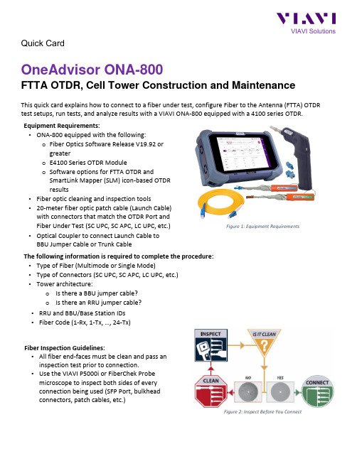
Quick CardOneAdvisor ONA-800FTTA OTDR, Cell Tower Construction and MaintenanceThis quick card explains how to connect to a fiber under test, configure Fiber to the Antenna (FTTA) OTDR test setups, run tests, and analyze results with a VIAVI ONA-800 equipped with a 4100 series OTDR. Equipment Requirements:• ONA-800 equipped with the following:o Fiber Optics Software Release V19.92 or greatero E4100 Series OTDR Moduleo Software options for FTTA OTDR andSmartLink Mapper (SLM) icon-based OTDR results• Fiber optic cleaning and inspection tools• 20-meter fiber optic patch cable (Launch Cable) with connectors that match the OTDR Port and Fiber Under Test (SC UPC, SC APC, LC UPC, etc.) • Optical Coupler to connect Launch Cable to BBU Jumper Cable or Trunk CableFigure 1: Equipment RequirementsThe following information is required to complete the procedure: • Type of Fiber (Multimode or Single Mode)• Type of Connectors (SC UPC, SC APC, LC UPC, etc.) • Tower architecture:o Is there a BBU jumper cable? o Is there an RRU jumper cable? • RRU and BBU/Base Station IDs • Fiber Code (1-Rx, 1-Tx, …, 24-Tx)Fiber Inspection Guidelines:• All fiber end-faces must be clean and pass an inspection test prior to connection.• Use the VIAVI P5000i or FiberChek Probe microscope to inspect both sides of every connection being used (SFP Port, bulkhead connectors, patch cables, etc.)Figure 2: Inspect Before You ConnectConnect to Fiber Under Test (FUT):All fibers and connectors should pass fiber inspection prior to connection, as described on page 1. The OTDR may be connected to the FUT as follows:Figure 3: Tower Architecture with BBU Jumper Figure 4: Tower Architecture, no BBU Jumper1.Inspect and clean the OTDR port on top of the test set.2.If the interface to the FUT is the BBU Jumper or Trunk Cable, connect the cable to an optical couplerwith the same connector type.3.Inspect and clean the FUT connected to the coupler or Optical Patch Panel (OPP).4.Inspect and clean fiber end face of the Launch Cable.5.Connect the Launch Cable to the OTDR port.6.Inspect and clean the other fiber end face of the Launch Cable.7.Connect the Launch Cable to the coupler or OPP leading to the RRU.Launch and Configure FTTA OTDR:Figure 5: Home Screen1.Press the Power button to start the test set.2.Tap to display the Home screen.3.Tap to display test selections.4.Tap the Fiber 1 selection to display OTDR module test selections. Note: TheModel number of your OTDR is displayed in the parenthesis.5.Tap to launch the FTTA OTDR test application.Figure 3: FTTA OTDR6.Tap the soft key to display the File Explorer.Figure 4: File Explorer7.Navigate to the ONA-800/disk/config/FTTA folder.8.Select FTTA_RRU_Maintenance.SM-OTDR for testing to an RRU at the far-end, orSelect FTTA_RRU_ConstrLoop.SM-OTDR for testing to a loopback at the far-end.9.Tap the and tap soft key to display FTTA OTDR Setup.Figure 5: Setup10.Configure Analysis settings as follows:•Set BBU Jumper to Yes if there is a BBU Jumper Cable between the Launch Cable and OVP;Set BBU Jumper to No if the Launch Cable is directly connected to the OVP.•Set RRU Jumper to Yes if there is a Junction Box/OVP at the top of the tower between the Trunk Cable and RRU; Set RRU Jumper to No if there is no Junction Box or no RRU Jumper.•Leave other settings at default values.11.Configure Link Description settings as follows:•Set Base Station ID to the Base Station or BBU Identifier.•Set RRU ID to the RRU Identifier or sector (Alpha, Beta, Gamma).•Set Fiber Code to the fiber number and polarity using the up and down arrows.•Set Change Fiber Nbr to Increment.•Set Distance Unit to feet or meter.Run Test:Press the icon to start the test. The OTDR will perform an auto-configuration, Connection Check, and Acquisition on each wavelength. If the Connection is Bad, repeat steps 1 through 7 on page 2, to ensurethe patch cable is clean and undamaged. Results will be auto-stored to the current directory.View Results:Result may be displayed in 3 different formats: SmartLink, Trace, or Table. The view is selected at the topof the display.Figure 6: View selection•SmartLink view:o In the upper display, the FUT is displayed as a series of icons representing events (end-of-fiber, launch cable, connector, etc.). Swipe left to display additional icons/events.o The center of the display shows summary results per wavelength. Acquisitions for which all events are acceptable are marked with a green check.o Tap on any icon to display event type and pass/fail status and to label each icon according to your tower architecture, in the lower display:▪BBU: Connection (coupler) between launch cable and BBU Jumper Cable▪BOT TWR: Optical Patch Panel at bottom of tower▪TOP TWR: Junction Box/Patch Panel at Top of tower▪RRU: End of RRU Jumper CableFigure 7: SmartLink ViewVIAVI SolutionsContact Us +1 844 GO VIAVI ) (+1 844 468 4284) To reach the VIAVI office nearest you,visit /contacts. © 2021 VIAVI Solutions Inc.Product specifications and descriptions in thisdocument are subject to change without notice.• Trace view :o Results for each wavelength are shown in different colors in the top section of the display. Each event iso Tap the icon to Auto-zoom the trace.o Tap 1 or 2 at the top of the display to toggle between results for the two wavelengths.Figure 8: Trace View• Table View: Each event on the FUT is displayed in tabular format.Figure 9: Table View。
- 1、下载文档前请自行甄别文档内容的完整性,平台不提供额外的编辑、内容补充、找答案等附加服务。
- 2、"仅部分预览"的文档,不可在线预览部分如存在完整性等问题,可反馈申请退款(可完整预览的文档不适用该条件!)。
- 3、如文档侵犯您的权益,请联系客服反馈,我们会尽快为您处理(人工客服工作时间:9:00-18:30)。
操作员手册手扶式振动压路机RS 800ARSS 800A5000405668 050811版权须知© 2012威克诺森公司版权所有。
保留所有权利包括复制和分发权利。
本出版物可由机器的初始买方影印。
未经威克诺森公司书面明确许可,禁止进行任何其他类型的复制。
未经威克诺森公司授权的任何类型的复制或分发属于侵犯有效版权。
违反者将被起诉。
商标本手册引用的所有商标均为其各自所有者的财产。
制造商威克诺森马尼拉公司Lot 2, Blk 1 Phase , PEZA Drive, First Cavite Industrial Estate, Brgy. LangkaanDasmariñas, Cavite, Philippines电话:+63-(0)2-580-7136 传真:+63-(0)2-580-712翻译版说明本操作员手册为原创说明的翻译版本。
本操作员手册的原始语言为美式英语。
前言3 1.排放控制系统信息42.安全信息52.1操作安全 (6)2.2操作员使用内燃机时的安全事项 (7)2.3维修安全 (8)2.4标签位置 (9)2.5安全标签 (10)3.技术参数133.1发动机 (13)3.2压路机 (14)3.3润滑 (14)3.4尺寸 (15)4.操作164.1操作和维修位置 (16)4.2应用 (18)4.3推荐的燃油 (RS 800A, RSS 800A) (18)4.4启动前 (19)4.5若要启动 (RS 800A) (20)4.6若要停止 (RS 800A) (20)4.7若要启动 (RSS 800A) (21)4.8若要停止 (RSS 800A) (21)4.9方向和速度控制 (22)4.10激振器(振动)控制 (22)4.11供水系统 (23)4.12手柄调节 (24)4.13在斜坡上操作 (25)4.14翻倒 (25)4.15翻载 (25)5.保养265.1维护排放控制系统 (26)5.2期保养计划 (26)5.3润滑 (27)5.4储存 (29)5.5发动机机油 (30)5.6空气滤清器 (31)5.7火花塞 (32)5.8沉淀杯 (32)5.9化油器 (33)5.10刮棒 (34)5.11清洁机器 (34)5.12提起机器 (35)5.13运送机器 (36)5.14故障检修 (37)5.15接线图 (RSS 800A) (39)加利福尼亚州65 号提案警告:府确认会导致癌症、先天性缺陷或其他的生殖系统伤害的化学物质。
警告前言本手册可提供与安全操作和维护此型号威克诺森机器相关的信息和程序。
为您自己的安全着想和减少受伤的风险,请仔细阅读、理解和遵守本手册的所有指示。
随机保留本手册或其备份。
如果丢失了本手册或需要另外一本,请与威克诺森公司联系。
制造商在制造机器时充分考虑到了用户的安全问题;然而,任何不恰当的操作及维修都存在危险。
仔细遵循操作说明!如果你有任何关于本设备的操作或维修问题,请与威克诺森公司联系。
本手册所含的信息基于在出版前制造的机器编撰。
威克诺森保留在不作出通知的情况下更换信息的任何部分的权利。
保留所有权利,包括复制和分发权利。
© 2012威克诺森公司版权所有。
未经威克诺森公司明确书面许可,不得以电子、机械或者其他形式或手段(包括影印)翻印本出版物的任何部分。
未经威克诺森公司授权的任何类型的复制或分发都属于侵犯有效版权,而且将被起诉。
我们明确保留为改善我们的机器或其安全标准进行技术修改的权利,恕不另行就此作出通知。
排放控制系统信息1排放控制系统信息和保修排放控制保修及相关信息仅在美国及加拿大境内有效。
1.1排放控制系统保修声明有关适用的废气及蒸发排放物保修声明,请参阅所提供的发动机用户手册。
RS 800 /... 安全信息2安全信息本手册含有危险、警告、小心、 注意、 及注释等信号文字,必须遵循该等文字的指示,以减少人员受伤、设备损坏或使用不当的可能性。
这是安全警告标志, 用于提示您注意潜在的人身伤害危险。
必须遵守该标志后跟的所有安全信息指示,这样才能避免可能的伤亡事故。
危险表示存在如下危险状况:若不避免该状况,将会导致死亡或重伤。
警告表示存在如下危险状况:若不避免该状况,可能会导致死亡或重伤。
小心表示存在如下危险状况:若不避免该状况,可能会导致轻微或中等伤害。
注意:注意并未与安全警告标志配合使用, 它表示存在如下状况:若不避免该状况,将会导致财产损失。
注释:包含关于程序的重要额外信息。
危险警告小心安全信息 RS 800 /...2.1操作安全若要安全操作机器,必须熟悉机器和接受适当培训。
不当操作机器或由未经培训的人员操作机器非常危险。
阅读本手册所载的操作说明,熟悉所有控件的位置以及如何正确使用控件。
经验不足的操作员在获准操作机器前应接受熟悉机器的人员的指导。
2.1.1不得将本机用于预期用途以外的应用。
2.1.2不能在发动机运行时或关闭后即时接触发动机或消音器。
这些区域具有高温,会导致灼伤。
2.1.3不得使用并非威克诺森推荐的配件或附件。
否则可能会导致设备损坏或用户受伤。
2.1.4操作机器时始终穿上适合工地状况的防护服。
2.1.5始终留意活动部件,让双手、双脚和宽松的衣物远离机器的活动部件。
2.1.6在尝试操作机器前,应阅读、理解并遵循操作员手册中载列的程序。
2.1.7启动后务必立即检查所有控件能否正常工作!除非所有控件都正常工作,否则不得运行机器。
2.1.8始终留意工地上的其他设备和人员的位置变化和移动。
2.1.9在不平整的地面、山坡、松软或粗糙材料上操作时,始终留意表面状况的变化,并格外小心。
机器可能会意外移位或滑动。
2.1.10在坑道、沟渠或平台边缘附近操作时应格外小心。
检查确保地面足够稳固,能够支撑机器和操作员的重量,且并无机器滑动、掉落或翻倒的危险。
2.1.11操作机器时,确保所有安全装置和防护罩到位并处于良好的工作状态。
切勿修改或移除安全装置。
若任何安全装置或防护罩缺失或失灵,切勿操作机器。
2.1.12在向后或山坡上操作机器时,始终确保自己处在安全的位置。
与机器保持一定距离,以免在机器滑落或翻载时让自己陷入危险。
2.1.13操作机器时始终确保双脚站在地面上!操作时不要站在、坐在或骑在机器上。
警告RS 800 /... 安全信息2.2操作员使用内燃机时的安全事项内燃机在操作和加油期间存在特殊危险。
请阅读并遵守发动机用户手册的警告指示和以下安全指南。
若不遵守警告和安全标准,可能会导致重伤或死亡。
2.2.1操作机器时切勿吸烟。
2.2.2给发动机加油时切勿吸烟。
2.2.3不能对高温或正在运行的发动机加油。
2.2.4不得在火星或明火附近对发动机加油。
2.2.5不得在明火附近运行发动机。
2.2.6切勿在室内或密闭区域(如,深沟)内操作机器,除非已通过排气扇或排气管等装置提供足够的通风。
发动机废气含有一氧化碳。
这是无色无味的有毒气体。
暴露在一氧化碳下会导致失去知觉,几分钟即可致命。
2.2.7在通风良好的区域加油。
2.2.8加油后,牢固地盖上油箱盖。
2.2.9启动发动机前,检查燃油管道和油箱有无泄漏或裂痕。
若出现燃油泄漏或油管松脱,切勿运行机器。
2.2.10确保高温的排气管周围并无杂物,以减少意外着火的风险。
警告安全信息 RS 800 /...2.3维修安全维护不当的机器会造成安全危险!为确保机器长期安全和正确运行,必须定期进行保养和不时进行维修。
2.3.1切勿尝试在机器运行时对机器进行清洁和维修:旋转的部件会导致严重人身伤害。
2.3.2切勿在发动机运行的情况下拆除空气滤清器盖、纸滤芯或预滤器。
2.3.3切勿使用汽油或其他类型的燃油或易燃溶剂清洁部件,尤其是在密闭区域。
燃油和溶剂的蒸汽会导致爆炸。
2.3.4维修和保养后必须重新装上安全装置和防护罩。
2.3.5以威克诺森设计及认可的备件更换磨损或损坏的部件。
2.3.6保持机器清洁和标签清晰可读。
更换所有缺失或难以阅读的标签。
标签可提供重要的操作指示和关于危险和危害的警告。
2.3.7定期检查所有外部紧固件。
2.3.8确保牢固连接吊索、吊链、吊钩、装载台、千斤顶或其他类型起重设备,且这些设备具有足够承重能力,能够安全提升或支撑机器。
在提升机器时始终留意所在区域其他人员的位置。
2.3.9若汽油发动机的火花塞已拆除,切勿发动该溢油的发动机。
汽缸内的燃油会从火花塞口喷出。
2.3.10若汽油发动机溢油或闻到汽油气味,切勿进行火花测试。
火星会点燃汽油蒸汽。
2.3.11确保消音器周围的区域没有任何杂物(如树叶、纸、纸箱等)。
高温的消音器会点燃这些杂物,导致火灾。
2.3.12对于配备汽油发动机的机器,在维修前断开火花塞连接,以免意外启动。
警告RS 800 /... 安全信息2.4标签位置安全信息 RS 800 /...2.5安全标签威克诺森机器在需要的地方使用国际图示标签。
这些标签如下所示。
标签含义危险!发动机会排放一氧化碳,只能在通风良好的区域操作。
阅读操作员手册。
在机器附近不得存在火星、火焰或燃烧的物体。
加油前关闭发动机。
警告!高温表面小心!操作本机器前,阅读并理解随附的操作员手册。
若不能做到这一点,会增加您自己和其他人受伤的风险。
注意提升点。
警告!为防止听觉丧失,操作本机时应始终佩戴听觉保护装置。
RS 800 /... 安全信息系紧点水箱振动控制开/关控制杆:通过红色控制杆控制向前或向后运动。
润滑点:每工作 100 小时检查和润滑一次。
标签含义安全信息 RS 800 /...RS 800 /... 技术参数3技术参数3.1发动机发动机额定功率净额定功率符合 SAE J1349 标准。
实际输出功率随具体使用条件而异。
部件号RS 800A0630011RSS 800A 0630012发动机发动机类型四冲程,顶置气门,单缸发动机制造商本田发动机型号GX 340 K1 QA2GX 340 K1 QAE2额定速度时的最大额定功率千瓦(马力)7.1 (9.5) @ 3600 转/分钟火花塞(NGK) BR 6ES电极间距毫米(英寸)0.7-0.8 (0.028-0.031)工作速度转/分钟2400阀间隙(冷态)吸取:排气:毫米(英寸)0.15 (0.006)0.20 (0.008)空气滤清器类型双滤芯发动机润滑机油等级SAE 10W30维修级别 SF、SG 发动机机油容量升(盎司) 1.1 (37)燃油类型常规无铅汽油燃油油箱容量升(夸脱) 6.8 (7.2)技术参数 RS 800 /...3.2压路机3.3润滑项目号RS800A 0630011RSS800A 0630012压路机重量公斤(磅)450 (1000)465 (1025)压实效率平方米(平方英尺)/小时2630 (28300)向前运动速度(最大)米(英尺)/分钟0-61 (0-200)向后运动速度(最大)米(英尺)/分钟0-46 (0-150)振动频率赫兹(振动次数/分)70 (420)爬坡能力%15水箱容量升(加仑)30 (8)部件号RS 800A 0630011RSS 800A 0630012润滑齿轮箱类型/数量SAE 90W 齿轮润滑油 / 175 毫升(6.0 盎司)静液压传动SAE 10W30 SE 级润滑装置二号 EMB3.4尺寸4操作4.1操作和维修位置见图:wc_gr003471RSS 800A编号说明编号说明1手柄锁定销7激振器控件2洒水管8加水口盖3水量控制阀9燃料箱4刮土板10吊眼5栓系点11水压驱动释放6向前 / 向后控制杆12控制箱RS 800A编号说明编号说明1手柄锁定销7激振器控件2洒水管8加水口盖3水量控制阀9燃料箱4刮土板10吊眼5栓系点11水压驱动释放6向前 / 向后控制杆122345891011671wc_gr0034714.2应用本机器用于压实沙砾、碎石、土壤和沥青。