MT3339
人教版同步轻松练习英语PEP八年级上册听力材料综合检测附答案C001-088

).-#6?3?+B,%.--+)
()0)%IK)04-+)
-+K9A9,3-+%
&%3>*3>
5%90)*90)
2%*9>**9>
V%*)0)**)0)
! "
DS%<)3>-@?)+-8:(
9F,)0(3>@3,,@)>3>,)0%
! "
&%@--13+:
5%,-@--1
2%@--1)?
!"#$%
!"# !"# !" ! " # $ % & ' ( ) * + , #$
%$
! "#$%"$
!%"&' ()*+,- $.
!%&%'()*)+,,-.)* /-0123,4%
5%6+,();--%
2%6+,()L-8+,93+>%
!M%N(9,?-*)1+-*9P-8,V9K)
&%<)(9>9A-@?%
5%<)(80,>(3>F--,%
2%<)(80,>(3>@):%
!Q%<-*3>,()*)9,()0+-*
&%6,B>(-,%
5%6,B>093+4%
!ZC
$#%)UX>94>,()0)*3@@P)9>,-0L,-#43;+)?,-:-A@3LP3+:*3,( L4A@9>>L9,)>%
carrier开利空调

Jason
3318
Jenny
3271 2.3E+07 李金玉开利J中es国sica Lee 3146
张海生
2306331 张梅芳 8
2.3E+07 郭媛媛
Fax 2.3E+07 祝峥渊 Eileen
3305 2.3E+07 查宏卫
Reception
张卫民
3322 2.3E+07 郭玥
3300 3272 3273
3519 2.3E+07
FP&A(Distribution)
姚振凯
IT
刘志国
3316 2.3E+07 王莉
Raymond 3278 2.3E+07 牛娲
3326 2.3E+07
Fielding 3277 2.3E+07 吴钧
3337 2.3E+07
Alan
3276 2.3E+07 郑伟民
3355 2.3E+07 孙洁敏
3515 2.3E+07
LCML
David
3503 2.3E+07
3504 2.3E+07
3505 2.3E+07
3506 2.3E+07
3507 2.3E+07
3508 2.3E+07
2.3E+07 汪涛
3408 2.3E+07 刘溯
Rex
3509 2.3E+07
2.3E+07 岳海峰
3407 23063407 徐巍
冯飚
Annie
3283
3284
Jack
3285
Carrier开利空调上海 namelist

煤矿用电缆型号及规格

煤矿用电缆型号及规格MT 818《煤矿用电缆》,按部分发布,拟分为13个部分:第1部分:移动类软电缆一般规定移动类软电缆电压:额定电压用U0/U表示,单位为kV。
U0表示任一主绝缘导体与“地”(金属屏蔽、金属套或周围介质)之间的电压有效值;U为多芯电缆或单芯电缆系统任意两相导体之间的电压有效值。
在交流系统中,电缆的额定电压应至少等于使用电缆的系统的标称电压,这个条件对U0和U值均适用移动类软电缆命名原则:移动类软电缆的命名由七部分组成:其中:第一、第二、第三、第四部分构成电缆的型号;第五、第六、第七部分构成电缆的规格。
第一部分:用大写字母M表示煤矿用电缆的系列代号。
第二部分:使用特性代号,反映电缆所使用的场合,C:采煤机用,M:帽灯用,Y:采煤设备(移动)用,Z:电钻用。
第三部分:电缆的结构特征,B:编织加强;J监视或辅助芯线;P:非金属屏蔽;PT:金属屏蔽;Q:轻型;R:绕包加强。
第四部分:用阿拉伯数字表示额定电压U0/U,单位为千伏(kV)。
第五部分:用阿拉伯数字分别表示动力线芯数及标称截面积,二者之间以“×”连接。
标称截面积单位为平方毫米(mm2)。
第六部分:用阿拉伯数字分别表示地线芯数及标称截面积,二者之间以“×”连接。
标称截面积单位为平方毫米(mm2)。
第七部分:用阿拉伯数字分别表示辅助线芯数及标称截面积,二者之间以“×”连接。
标称截面积单位为平方毫米(mm2)。
移动类软电缆线芯规格:1、1.5、2.5、4、6、10、16、25、35、50、70、95、120、150、185、240、240、300、400、第2部分:额定电压1.9/3.3 kV及以下采煤机软电缆额定电压1.9/3.3 kV及以下采煤机软电缆型号:MC———0.38/0.66 采煤机橡套软电缆MCP——0.38/0.66 采煤机屏蔽橡套软电缆MCP——0.66/1.14 采煤机屏蔽橡套软电缆MCP——1.9/3.3 采煤机屏蔽橡套软电缆额定电压0.38/0.66 kV采煤机软电缆规格如下:3×16+1×4 3×25+1×6 3×35+1×6 3×50+1×10 3×70+1×16 3×95+1×25 3×120+1×25额定电压0.66/1.14 kV采煤机软电缆规格如下:3×25+1×6 3×35+1×6 3×50+1×10 3×70+1×163×95+1×25 3×120+1×25 3×150+1×35额定电压1.9/3.3 kV采煤机软电缆规格如下:3×25+1×10 3×35+1×10 3×50+1×16 3×70+1×253×95+1×25 3×120+1×35 3×150+1×35第3部分:额定电压1.9/3.3 kV及以下采煤机屏蔽监视加强型软电缆额定电压1.9/3.3 kV及以下采煤机屏蔽监视加强型软电缆型号:MCPJB——0.66/1.14,采煤机屏蔽监视编织加强型橡套软电缆;电缆可直接拖曳使用。
联发科MTK芯片型号资料大全

联发科MTK芯片型号资料目录:使用浏览器打开,点击型号即可下拉MT2503MT6737MT6735MT8176MT6580MT6572MT6753 MT8735MT6758MT8163MT6750MT6582MT6261MT2502 MT7623MT8783MT6797MT7628MT7662MT6755MT2601 MT6757MT6570MT7601MT7688MT8321MT2523MT7687 MT6592MT2511MT6732MT5931MT2625MT6752MT2533 MT6799MT6738MT5596MT6260MT8382MT8693MT8127 MT7621MT8173MT6589MT7620MT6280MT6571MT5505 MT2501MT7615MT7603MT6795MT6575MT6595MT8685 MT7681RT5572MT3333MT6516MT6328MT3332MT6577 MT6573MT5580RT3573MT7697MT3303RT5370MT8580MT3339 MT8312MT1389MT5592RT3593MT1887MT3337MT8502 MT6513MT8516MT5398MT1865RT3062MT6225MT1398RT3562 MT6276MT5561MT7610RT3070MT6588MT1862MT6290MT1959RT5592MT7612MT6169RT3662MT6515MT5396MT6228 MT6517MT6229RT3883MT6223MT6235MT8563MT6250 MT8507MT8553MT6205MT6227MT6226MT6255MT6253 MT8389MT8665MT8392MT2503联发科技MT2503基于高度集成的超小型系统级封装,整合蓝牙3.0、多星系GNSS系统和2G基带,搭载集成内存的ARMv7微控制潜在应用领域包括具备简单应用功能的可穿戴设备、可移动的资产跟踪设备、注重安全的工业应用。
LOCOSYS GPS智能天线模块用户手册说明书
5 Software interface 5.1 NMEA output message
Table 5.1-1 NMEA output message
NMEA record
Description
GGA
Global positioning system fixed data
GLL
Geographic position - latitude/longitude
Page 2/20
LOCOSYS Technology Inc.
20F.-13, No.79, Sec. 1, Xintai 5th Rd., Xizhi District, New Taipei City 221, Taiwan
℡ 886-2-8698-3698 886-2-8698-3699
GSA
GNSS DOP and active satellites
GSV
GNSS satellites in view
RMC
Recommended minimum specific GNSS data
VTG
Course over ground and ground speed
GGA--- Global Positioning System Fixed Data
4 GPS receiver
LOCOSYS Technology Inc.
20F.-13, No.79, Sec. 1, Xintai 5th Rd., Xizhi District, New Taipei City 221, Taiwan
℡ 886-2-8698-3698 886-2-8698-3699
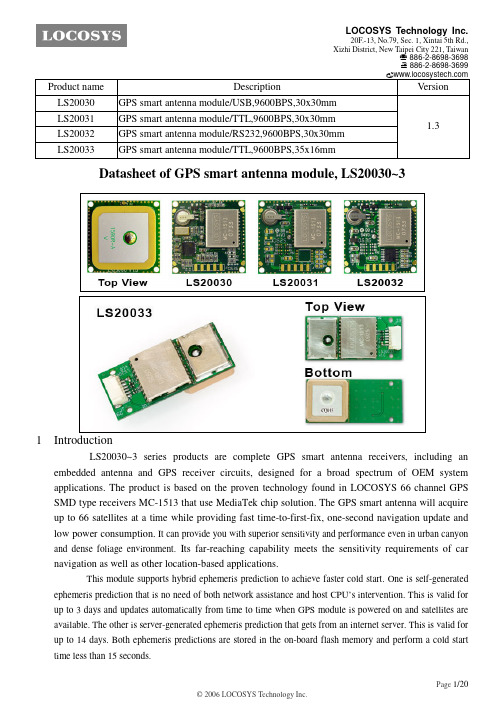
Product name LS20030 LS20031 LS20032 LS20033
C语言程控

/****************************************************************************** *******************//**** 参数配置****//****************************************************************************** *******************//* 此配置文件包含几个部分,每部分您只能设置一个参数.* 1 - 基本设置- you must select an option in every block.* this assumes you have 4 channels connected to your board with standard ESCs and servos.* 2 - 飞机设置- you likely want to check for options for your copter type* 3 - 信号接收设置- 注: 如果您使用的是标准接收机,请不要设置此部分* 4 - 设置扩展CPU与板* 5 - 扩展设置- select alternate RX (SBUS, PPM, etc.), alternate ESC-range, etc. here* 6 - 可选设置- enable nice to have features here (FlightModes, LCD, telemetry, battery monitor etc.)* 7 - 开发者高级设定- 警告:请谨慎的更改此部分的设置,否则飞行器将引发不可预知的灾难!!!*//* 备注:* 1. 参数标记(*) 的可通过LCD液晶屏显示设置,点击写入E2PROM中,可保存所设置的参数。
* 改变config.h 后,请重新编译写入飞控中,并点击'Reset' 重启飞控使配置生效。
MODEC AIR MOTOR 系列 MT 和 MR 用户手册说明书

Manuel utilisateur Mise à jour : 8 November 2010Index1.General description and identification Page: 32.Safety Instructions Page: 43.How to start an air motor Page: 54.Maintenance and repair Page: 95. ATEX certificate Page: 116.Notes Page: 12Manuel utilisateur Mise à jour : 8 November 2010DECLARATION OF INCORPORATION OF PARTLY COMPLETED MACHINERY (Directive 2006/42/EC of the European parliament and of council of 17 May 2006) and EC DECLARATION OF CONFORMITY (ATEX DIRECTIVE 94/9/EC)I undersigned Pierre-Yves Cote / President of Modec air motors / Z.I. Les Bosses 26800 Etoile sur Rhône / France / Siret : 493 748 917 000 17⇒Declare that the following ranges of air motors:∙MT05, MT07, MT10, MT20, MT25, MT30, MT40, MR07, MR08, MR10,MR20, MR25, MR30, MR40, NT05, NT07, NT10, NT20, NT25, NT30, NT40, NR07, NR08, NR10,NR20, NR25, NR30, NR40.∙Offering under 6 bars from 40 Watts to 3500 Watts∙Made of one pneumatic section, one planetary gear box, one mounting flange and one output shaft.Applies with the essential requirements of the Directive 2006/42/EC of the European parliament and of council of 17 May 2006. The relevant documentation is complied in accordance with part B of Annex VII of the above Directive.Those documents can be transmitted in response to a reasoned request by the national authorities.Our motors considered as partly completed machinery must not be put into service until the final machinery into which it is to be incorporated has been declared in conformity with the provisions of this Directive.⇒Declare that the following ranges of air motors:∙MT05, MT07, MT10, MT20, MT30, MR07, MR08, MR10,MR20, MR30,∙Offering under 6 bars from 40 Watts to 3500 Watts∙Made of one pneumatic section, one planetary gear box, one mounting flange and one output shaft.∙Marked with the following mention : MODEC/France/2009 / Modec part number / ATEX II 2 G/D c IIC T6/T4 / LCIE 09 ATEX 1003XApplies with the essential requirements of the Directive 94/9/EC : Directive 94/9/EC of the European Parliament and the Council of 23 March 1994 on the approximation of the laws of the Member States concerning equipment and protective.Origin : All motors have been produced and mounted in France.Etoile sur Rhône November 3rd , 2010Pierre-Yves Cote / President / Modec S.A.S.Manuel utilisateur Mise à jour : 8 November 20101 – General description and identification of motorsMODEC air motors are composed of the following:1. A Pneumatic part linked to the power range.2. A Planetary geared reduction system enabling to adapt torque and speed.3. A Mounting flange.4. A shaft, it can be of various types.Your air motor is the combination of these 4 items. The numbering MODEC identifies precisely all the components of your motor..Reference motor:Motor serial number:Date : Stamp :Manuel utilisateur Mise à jour : 8 November 20102 - Safety InstructionsTo read carefully prior to any installation, use and maintenance.∙Changes may be made to the motors described in this document. We reserve the right to change, without notice, the characteristics thereof.∙This document is unique and it is the property of MODEC Company. It can not be corrected, modified or duplicated without written agreement.∙This document does not replace the security rules set by the Labor Code or any other laws applicable in the place of use of the motor.Operators using or near the motors must bear the following protections, depending on the site or they are used. Additional protections can be expected.This operator’s manual must always be available near the place of use of motor. It must be read and used by all persons connected with the wok carried out by the latter.∙All changes to motors or its accessories most be approved by the manufacturer by writing.∙Motors, during use are sources of noise. It is recommended to use adequate hearing protection.∙Excessive lubrication can cause damage to the operator, because it involves spraying in its immediate environment of a certain quantity of oil in the air from the motor.∙Motor can produce vibrations. Frequent and prolonged exposure to these high intensity vibrations can cause disorders and diseases that affect especially hands andarms. The effects are not yet well known because they depend on several factors,including: the type of work, the physical conditions of the operator, the duration andexposure conditions.* Lack of compliance with instructions contained in this manual, as well as changes, omissions and use of spare parts that don’t meet the specifications detailed in this manual, relieves the manufacturer from any liability relating to proper use, proper functioning and protection of persons and equipment.Manuel utilisateur Mise à jour : 8 November 20103 – How to start an air motor✓Transporting the motor:On receipt of the motor, make sure that the package and the motor have not been damaged. If any damage is noticed, please contact MODEC. Keep the package until you have set up the motor. When moving to another workstation or another workshop, make sure that you cautiously transport the motor. Use an appropriate package to avoid damaging the motor.✓Installing the motorPatterns of pneumatic feeding of MODEC motors (see the diagrams below)Before to make any operation to start an air motor, it must ensure good quality of network air to protect the motor against pests, dirt and rusting.This includes:∙The supply pressure must never exceed the maximum working pressure of the motor is6 bars, whichever is greater using a pressure regulator∙The flow must be sufficient for the motor∙The installation of a lubricant filter between the plug and the input fitting is essential for the motor with 50 micron filtration and lubrication oil 50 mm3 per m3 of air consumed.∙It is advisable to connect each motor to the supply system by inserting a switch tire safety, in order to avoid any whiplash that could cause a pipe broke or detached ∙Don’t use tubes damaged or worn. Inspect carefully feeding tubes before use: a ruptured tube can cause some damage.∙The feeding tube should be oil resistant, abrasion and adapted to the pressure of the motor.∙The excessive length of tube should be avoided.Manuel utilisateurMise à jour : 8 November 20101.Filter2.Pressure regulator3. Lubricating system4. Flow control system5. Distributor 3/26. Non reversible motor Direction of rotation left or rightDirection of rotation reversible For a reversible engine it is necessary that the opposite opening of the feed in air is for the exhaustManuel utilisateur Mise à jour : 8 November 2010Motor lubricationTo maximize the life of your motor and guarantee their full power operation, it must be absolutely lubricated with 50 mm3 per m3 of air,see table below (1 drop = 15 mm3).The pneumatic oil used should have a viscosity between 22 and 46 cst depending on the temperature of motor operation (e.g. 40 ° C the viscosity of the oil should be between 22 and 30 cst) and having a temperature self-ignition above 260 ° CMotor with « KIT NO LUB »The motors without lubrication don’t require any additional oil in the air. However, beware the quality of the area (watch the water content in the air system)Manuel utilisateur Mise à jour : 8 November 2010✓Installing the motor after having validated the previous step ∙Set the motor on your system through the flange supplied by MODEC.∙Never operate the engine without a proper system to isolate the source.∙Clean the feeding tube of dirt and condensation and fittings.∙Connect the feeding tube to the engine before opening the air supply.∙Never forget that the tube should be examined carefully after use.✓Starting up of the motor after having validated the previous stepsNote that MODEC motors are always tested and lubricated on manufacturing process.∙First starting up, make pulses of successive air in the motorVerify that there is not any malfunction of the motor (sounds abnormal or excessive heating)✓Motor starts in ProductionAt the start of motor in production, it is important to ensure continuity in time of validation of previous steps.✓Long inactivity from the motor∙When a long inactivity from an air motor, this one must keep out from an humid environment to avoid the formation of rust on the internal mechanical parts because it can reduce this early life.∙To return to service the motor, insert 3 drops of pneumatic oil into the air inlet and repeat the instructions of starting up described above.✓Recycling your motor∙ A pneumatic tool is made up of steel, cast-iron, brass and plastic components. All these items can be salvaged and are not dangerous for the surroundings and/or the safety of the staff. You may separate the different materials in order to reuse them.Manuel utilisateur Mise à jour : 8 November 20104 – Maintenance and repair procedure of an air motorGeneral recommendation∙Consider all the regulations put in place regarding safety and hygiene at work, and instructions in effect in the local framework for security including the conditions of the workplace, clothing and equipment of individual protection of the operator required by all applicable regulations.∙It is recommended that you keep a maintenance log for each operation made on the motor.Prevent any presence of foreign body in the system, by providing a clean work surface to protect sensitive internal moving parts against, contamination by dirt and foreign material use during installation and reassembly because it may cause a deterioration of mechanical parts.∙The air motor maintenance will be performed by persons competent and trained by MODEC or our department after sales service is available for this purpose.∙It is advisable to check and clean the air motor every six months when used daily, as recommended to clean the coupling-filter fitting the motor.∙ In case of engine malfunction after a period of inactivity, a few drops of oil into the fitting of air branch connection.∙Unplug systematically motor branch connection before starting an operation of substitution, adjustment, maintenance or dismantling.∙After every maintenance, the engines will be tested to verify their good functioning.Use only replacement parts and original elements ensuring the maintenance, lubrication and sealing recommended by the manufacturer.Manuel utilisateurMise à jour : 8 November 2010 Right angle type MR greasingYour motor has been delivered with a greased bevel gear. The frequency of greasing operation is depending of the motor use, which are identified in 3 stages: ∙ low load ∙ medium load∙ heavy load and/or shockRight angle greasingGammes de moteurs Air motors ranges Contraintes d'utilisations Contraint of use FrequenceFrequencyQuantités Quantity’sMarque recommandée Brand recommendationMR07;08;09;10;20;25Faible Chargelow load1000 H 10 to 20 mLORAPI 606 CTDMEP 2Charge moyenne Medium load500 H Charge importante et choc Heavy load and Shock200 H MR26; 30;40Faible Charge low load900 H40 to 60 mL ORAPI 606 CTDMEP 2Charge moyenne Medium load400 H Charge importante et choc Heavy load and Shock150 HMT moto reducer type greasingYour motor has been delivery with permanent greasing, if required the reducer can be re-greased:- old grease must be removed carefully- 50 to 70mL of grease 606 ORAPI CTDMEP 2 has to be distribute uniformly inside the reducerManuel utilisateur Mise à jour : 8 November 2010In case of failure, rapid diagnosisIf after all checks listed in this manual your motor is not working properly, please contact the "Service After Sale" from MODEC which tells you what to do. ……………………………………………………………………………………………………………………………………………………………………………………………………………………………………………………………………………………………………………………………………………………………………………………………………………………………………………………………………………………………………………………………………………………………………………………………………………………………………………………………………………………………………………………………………………………………………………………………………………………………………………………………………………………………………………………………………………………………………………………………………………………………………………………………………………………………………………………………………………………………………………………………………………………………………………………………………………………………………………………………………………………………………………………………………………………………………………………………………………………………………………………………………………………………………………………………………………………………………………………………………………………………………………………………………………………………………………………………………………………………………………………………………………………………………………………………………………………………………………………………………………………………………………………Manuel utilisateur Mise à jour : 8 November 2010…………………………………………………………………………………………………5 - ATEX certificateThe certificate below is valid only if the motor has the legal mention engraved according to the ATEX directive EN-13463-1 of 2002.Manuel utilisateur Mise à jour : 8 November 2010NOTES …………………………………………………………………………………………………………………………………………………………………………………………………………………………………………………………………………………………………………………………………………………………………………………………………………………………………………………………………………………………………………………………………………………………………………………………………………………………………………………………………………………………………………………………………………………………………………………………………………………………………………………………………………………………………………………………………………………………………………………………………………………………………………………………………………………………………………………………………………………………………………………………………………………………………………………………………………………………………………………………………………………………………………………………………………………………………………………………………………………………………………………………………………………………………………………………………………………………………………………………………………………………………………………………………………………………………………………………………………………………………………………………………………………………………………………………………………………………………………………………………………………………………………………………………………………………………………………………………………………………………………………………………………………………………………………………………………………………………………………………………………………………………………………………………………………………………………………………………………………………………………………………………………………………………………………………………………………………………………………………………………………………………………………………………………………………………………………………………………………………………………………………………………………………………………………………………………………………………………………………………………………………………………………………………………………………………………………………………………………………………………………………………………………………………………………………………………………………………………………………………………………………………………………………………………………………………………………………………………………………………………………………………………………………………………………………………………………………………………………………………………………………………………………………………………………………………………………………………………………………………………………………………………………………………………………………………………………………………………………………………………………………………………………………………………………………………………。
- 1、下载文档前请自行甄别文档内容的完整性,平台不提供额外的编辑、内容补充、找答案等附加服务。
- 2、"仅部分预览"的文档,不可在线预览部分如存在完整性等问题,可反馈申请退款(可完整预览的文档不适用该条件!)。
- 3、如文档侵犯您的权益,请联系客服反馈,我们会尽快为您处理(人工客服工作时间:9:00-18:30)。
Pin Assignment and Descriptions .............................................................................................. 9 2.1 2.2 Pin assignment (top view) .................................................................................................... 9 Pin descriptions .................................................................................................................... 9
ห้องสมุดไป่ตู้
Description Update TFBGA ball map and pin description Update pin-mux and strap information Update RF part description Update System overview Update RF part electrical characteristics Update analog part electrical characteristics Update RF LDO electrical characteristics Update power scheme Add RTC domain power scheme Modify according to YC Chien’s suggestion Update by JN Yang about UART baud rate and SPI/I2C clock rate Update RF related description Update system overview by Andy Lee Update host interface related description Update power scheme Update block diagram Update crystal frequency range Update external LNA related information Update power scheme diagram and EEPROM I2C interface timing diagram Update power related description Update footprint size Change minimum input power to 2.7V Sync PIN naming of DC characteristic table and change minimum input power to 2.8V Update power scheme and RF information Update description of 32K_OUT pin Add ECLK and SYNC description Add 1.2V IO characteristic for TIMER and 32K_OUT and update serial flash size to 128Mb Remove description about factory testing and internal SRAM size Remove description about strap function tcxo on/off 1. Update RTC leakage information to typ 2. Update package dimensions information Update RF related descriptions 1. Remove Vcc description in 6.3.1 2. Add strap pin tldo_sw_sel description Change MAX of VIH for TIMER and 32K_OUT to 3.6V Change description in 5.20 about CLDO off Add RF LNA MIN of VGA gain and MAX of noise figure © 2011 MediaTek Inc. Page 2 of 37
Author Loris Li Loris Li Loris Li Loris Li Loris Li Loris Li Loris Li Loris Li Loris Li Loris Li Loris Li Loris Li Loris Li Loris Li Loris Li Loris Li Loris Li Loris Li Loris Li Loris Li Loris Li Loris Li Loris Li Loris Li Loris Li Loris Li Loris Li Loris Li Loris Li Loris Li
Add top mark description Add power up sequence diagram for external LDO mode Add power up sequence diagram for low power/cost mode Remove power up sequence diagram for low power/cost mode and add power on/off reset behavior diagram in chapter 5.10.
0.31
2011/04/01
Loris Li
0.32 0.33
2011/04/07 2011/04/12
Loris Li Loris Li
MediaTek Confidential
This document contains information that is proprietary to MediaTek Inc. Unauthorized reproduction or disclosure of this information in whole or in part is strictly prohibited.
MT3339 GPS All-in-One Solution Confidential A
Table of Contents
Document Revision History .................................................................................................................. 2 Table of Contents ................................................................................................................................... 4 1 System Overview .......................................................................................................................... 7 1.1 1.2 2 General descriptions ............................................................................................................. 7 Features................................................................................................................................ 8
MediaTek Confidential
© 2011 MediaTek Inc.
Page 3 of 37
This document contains information that is proprietary to MediaTek Inc. Unauthorized reproduction or disclosure of this information in whole or in part is strictly prohibited.
MT3339 GPS All-in-One Solution Data Sheet
Version: Release date:
1.05 2011-09-19
© 2011 MediaTek Inc. This document contains information that is proprietary to MediaTek Inc. Unauthorized reproduction or disclosure of this information in whole or in part is strictly prohibited. Specifications are subject to change without notice.
Loris Li Loris Li Loris Li Linda Chen Loris Li Loris Li Loris Li Loris Li Loris Li Loris Li Loris Li Loris Li Loris Li
Update package dimension total height to max 1mm Change RF LDO related voltage description Add reset controller power on reset diagram Update to MTK standard format Change LDO Imax related description Review electrical characteristics Review feature and internal description. Update TCXO_SW SPEC 1. 2. Change AVDD_RFCORE Vmin SPEC from 1.14 to 1.16 Change package name TFBGA to VFBGA