C8051F125
C8051F系列较8051新增功能总汇
高速SoC单片机C8051F美国Cygnal公司专门从事混合信号系统芯片(SoC)单片机的设计与制造。
公司更新了原51单片机结构,设计了具有自主产权的CIP-51内核,运行速度高达每秒25MIPS。
现已设计并为市场提供了29个品种的C8051F系列SoC单片机,预计今年年内还将完成20多个新的SoC单片机的设计。
C8051F系列是集成的混合信号系统芯片SoC单片机,具有与MCS-51内核及指令集完全兼容的微控制器,除了具有标准8051的数字外设部件之外,片内还集成了数据采集和控制系统中常用的模拟部件和其它数字外设及功能部件(参见图1)。
C8051F系列是真正能独立工作的SoC。
CPU有效地管理模拟和数字外设,可以关闭单个或全部外设以节省功耗。
FLASH存储器还具有在线重新编程的能力,即可用作程序存储器又可用于非易失性数据存储。
应用程序可以使用MOVC和MOVX指令对FLASH进行读或改写。
C8051F系统工作电压为2.7V~3.6V,典型值为3V。
I/O、RST、JTAG 引脚均允许5V电压输入。
CPU的独特之处与标准8051完全兼容C8051F系列单片机采用CIP-51内核,与MCS-51指令系统全兼容,可用标准的ASM-51、Keil C高级语言开发编译C8051F系列单片机的程序。
高速指令处理能力标准的8051一个机器周期要占用12个系统时钟周期,执行一条指令最少要一个机器周期。
C8051F系列单片机指令处理采用流水线结构,机器周期由标准的12个系统时钟周期降为1个系统时钟周期,指令处理能力比MCS-51大大提高。
CIP-51内核70%的指令执行是在一个或两个系统时钟周期内完成的,只有四条指令的执行需4个以上时钟周期。
CIP-51指令与MCS-51指令系统全兼容,共有111条指令。
增加了中断源标准的8051只有7个中断源。
C8051F系列单片机扩展了中断处理,这对于实时多任务系统的处理是很重要的。
C8051F系列单片机的FFT实现

Rev. 1.1 12/03Copyright © 2003 by Silicon LaboratoriesAN142-DS11AN142FFT R O U T I N E S F O R T H E C8051F12X F A M I L Y Relevant DevicesThis application note applies to the following devices:C8051F124, C8051F125, C8051F126, and C8051F127.IntroductionThe Fast Fourier Transform (FFT) is an efficient method for calculating the Discrete Fourier Trans-form (DFT) of a signal. This note provides a brief introduction to the FFT, and describes two example FFT routines written in ‘C’ that have been opti-mized for execution time and RAM storage space on Silicon Labs microcontrollers. The example routines use the 10 or 12-bit ADC to collect theinput data for the FFT routine, and the results are sent out through the UART, where they can be dis-played using terminal software on a PC.Only the very basic aspects of the FFT that are nec-essary to describe the algorithms are presented here. A more detailed explanation of the DFT and the FFT can be found in References [1] and [2].Radix-2 FFT AlgorithmsThe output of the FFT is identical to the output of the DFT, but a number of redundant calculations have been eliminated to allow for faster computa-tion. For an N-point DFT, the required number of complex multiplications is N 2. For an N-point FFT,the number of complex multiplications required is:This optimization leads to a drastic speed improve-ment over the DFT as N becomes large. For exam-ple, a 64-point DFT requires 4096 complexmultiplications, while the corresponding FFT requires only 192. Using this and other optimiza-tions, an FFT can be calculated in a relatively short amount of time on a Silicon Labs 8051 processor.The FFT routines presented in this note are both Radix-2 Decimation-in-Time algorithms. Radix-2algorithms operate by separating the original DFT into a number of 2-point DFT computations. First,the original N-point DFT is split into two DFTs of N/2 points each. The resulting N/2-point DFTs are then each split into two N/4-point DFTs, and so on,until the number of points in each smaller DFT is reduced to two. This method requires that the FFT size be a power of two.The basic 2-point DFT performed in the Radix-2Decimation-in-Time algorithm is shown in Figure 1. This structure, named a “butterfly”, isused to perform all of the computations necessaryfor the FFT. The inputs (A and B) and the outputs (A’ and B’) of the butterfly are complex numbers containing the data that is being processed. W n rep-resents a complex sinusoidal value that is applied ateach stage of the FFT.N2---N 2log⋅Figure 1. Radix-2 Decimation-in-TimeButterfly StructureAN1422Rev. 1.1Index Bit ReversalThe FFT algorithms presented here are performed on the data in-place, to minimize the amount of temporary storage space required for intermediate data. To perform these algorithms in-place, either the input data or the output data of the FFT routine will be sorted in bit reversed order. To change between normal order and bit reversed order, each data point is swapped with another location in the data set determined by reversing the order of the bits in the sample index. For example, in a 16-point FFT, the sample stored at index 0001b (1 decimal) would swap locations with the sample stored at index 1000b (8 decimal). Locations where the bit reversed index are equal to the not bit-reversed index, such as 0110b (6 decimal) are not swapped. The order of operations in the FFT computation is determined by whether the inputs or the outputs of the FFT are sorted in bit-reversed order. Windowing Input DataThe FFT algorithm operates on a data set that rep-resents a finite length of time, but makes the assumption that the data set is periodic and repeated infinitely. When the sample set is repeated in this way, the last sample (index[N-1]) is adja-cent to the first sample (index[0]). As shown in Figure2, this can lead to a discontinuity in the sig-nal that the FFT “sees” when the data is not peri-odic over the sample set. Because of this, data is normally windowed before it is processed by an FFT routine. Windowing makes the data periodic over the sample set and removes any discontinuity between the first and last samples in the set. Because windowing changes the input data set, it produces some artifacts in the frequency domain. Windowing “spreads” the signal energy among multiple bins, as shown in Figure3. This energy spreading has the effect of attenuating the peak value of the signal. Most of the signal’s original content is stored in the “main lobe”, while a small amount leaks into the “side lobes”. The width of the main lobe and the height of the side lobes are dependent on the window algorithm that is applied to the data. Some common windows and their prop-erties are summarized in Table1 . Some equations for computing the window coefficients for an N-point FFT are listed in Table2 . More extensive information on window algorithms and their parameters can be found in Reference [3].AN142Rev. 1.13Figure 2. Time Domain WindowingAN1424Rev. 1.1Table 1. Window PropertiesMain Lobe Width Processing Gain Side Lobe Height None (Rectangular) 1 Bin 1.0-13 dBTriangular 3 Bins0.5-27 dBHanning 3 Bins0.5-32 dBHamming 3 Bins0.54-43 dBBlackman 5 Bins0.42-58 dBTable 2. Window Coefficient EquationsWindow EquationNone (Rectangular)W(n) = 10 ≤ n < NTriangular W(n) = n / (N / 2)W(n) = 2 - n / (N / 2)0 ≤ n ≤ N / 2 N / 2 < n < NHanning W(n) = 0.5 - 0.5cos(2πn / N)0 ≤ n < N Hamming W(n) = 0.54 - 0.46cos(2πn / N)0 ≤ n < NBlackman W(n) = 0.42 - 0.5cos(2πn / N) +0.08cos(4πn / N)0 ≤ n <N Figure 3. Window Effects in the Frequency DomainAN142Rev. 1.15Software ExamplesThis application note contains two FFT routines that are very similar. Both examples collect data from the ADC, window the collected data, perform an FFT, and print the results to the UART running at 115200 baud. The difference between the two example files is whether the inputs or the outputs of the FFT routine are in bit-reversed order. The first routine, “IntFFT_BRIN.c”, accepts input data sorted in bit-reversed order and produces outputsorted in normal order. The second routine,“IntFFT_BROUT.c”, accepts data sorted in normalorder and produces output sorted in bit-reversed order. The two examples produce identical results, but each has its advantages. Performing a bit-reversal sort takes some processing time and is not always necessary for every application. For example, an application that is performing peak frequency detection needs only to know which output bin of the FFT has the highest magnitude. Once this is determined, the frequency for that particular bin can be calculated by bit reversing only the bin of interest. In this example, the routine that accepts input data in normal order and produces outputs in bit-reversed order (IntFFT_BROUT.c) can be used without having to re-sort the output data after-wards.If the application requires that the output of the FFT appears in normal order, and the input to the routine is a real signal (not a complex input), the routine that requires bit-reversed input data (IntFFT_BRIN.c) may be a better choice. The rea-son for this is that the imaginary locations in the real input set can be assumed to be zero, and some processor time can be saved by only sorting the real data. In this example, the complex output of the FFT appears in normal order.Parameter SpecificationThe file “FFT_Code_Tables.h” contains code tables for FFT sizes from 4 points to 1024 points,and four different window types. Conditional com-pilation is used so that only the necessary tables for the desired FFT size and window type are included.The parameter NUM_FFT should contain the size of the FFT to perform. Valid FFT sizes for this example code are 4, 8, 16, 32, 64, 128, 256, 512,and 1024 points. The parameter WINDOW_TYPE should contain a number from 0 to 4, which speci-fies the desired window algorithm, according to Table 3 .One other parameter that affects the program oper-ation is the RUN_ONCE definition, which is con-tained in the main source file. If RUN_ONCE is zero, the program will continue to collect new data sets and perform FFTs on them. If RUN_ONCE is a non-zero value, the program will stop after one iter-ation.Data CollectionADC0 collects the data to process using Timer 3 as a start-of-conversion source. ADC0 is configured to sample at a speed determined by the SAMPLE_RATE constant, in single-ended mode on channel AIN0.0. Samples are collected and stored in the Real[] array. The 12-bit ADC data is left-jus-tified and stored as 16-bit data with trailing zeros.Once NUM_FFT samples have been collected,ADC0 interrupts are turned off, and the data is win-dowed.Table 3. Window Selection 0None (Rectangular)1Triangular 2Hanning 3Hamming 4BlackmanAN1426Rev. 1.1Window ImplementationAfter the data has been collected, it is windowed using the window selected by the WINDOW_TYPE constant (see Table3 ). The window information is stored in code space as a table of unsigned integer (16-bit) values. The integers represent a fractional number which can be computed by dividing the stored integer by 65536. For example, the value 32768 represents a multiplication value of 32768 / 65536, or 0.5. Because the windows are all sym-metrical about NUM_FFT/2, the window tables only contain values for one half of the window to save storage space. The window value at index NUM_FFT/2 is assumed to be equal to 1.0, and is not stored. The WindowCalc() function performs a multiplication of each input sample with its corre-sponding value in the window table. Table4 shows how the window table is indexed when multiply-ing.The WindowCalc() function also changes data that has been stored in single-ended (unsigned) format into differential (signed 2’s complement) format. This centers the data about 0x0000 to remove the DC bias. When the SE_data input variable is non-zero, each sample is XORed with the value 0x8000. This inverts the MSB of the data, which has the same effect as subtracting 0x8000 from all samples. If the SE_data variable is zero, the data is assumed to already be in 2’s complement format, and is not changed.FFT OptimizationsA number of optimizations were implemented in the example routines. The primary goals of these optimizations were to maximize the speed of the routine and to minimize the amount of RAM needed for data storage. The specifics of each opti-mization are detailed in the sections that follow. Integer Storage and Computation The FFT algorithm has an inherent processing gain. For a real input, the processing gain is equal to N/2, where N is the number of points in the FFT (the processing gain for complex inputs is equal to N). Because of this gain, more bits are required to store the output information of the FFT than are required to store the input information. Instead of using additional space, the example FFT routines use 16-bit signed integer values to store all input, output, and intermediate data. To compensate for the FFT processing gain, and to store all data as 16-bit num-bers, the computed values are divided by 2 after each butterfly calculation. Using this method, the overall gain of the FFT routine, not including win-dow gain, is 1/2 for a real input, and 1 for a com-plex input.Integer math is used to perform all calculations. This improves the speed of the FFT routine over fixed-point or floating-point math. Multiplication is avoided whenever possible, and all divide opera-tions are implemented using right shifts. Whenever this type of divide is performed, the result is rounded to counter the asymmetrical effects of truncating a 2’s complement number. If the number is negative, and the deleted bits are non-zero, a one is added to the result so that both negative and pos-itive numbers are always rounded towards zero. Sinusoid Table StorageTo reduce computation time, sine and cosine values are not calculated in real-time. Instead, they are pre-calculated and stored in code space. The SinTable[] array declared in “FFT_Code_Tables.h”Table 4. Window Index Decoding0 to (N / 2 - 1)MN / 2No Multiplication (N / 2 + 1) to (N -1)N - MN is represented by NUM_FFT in the software examples.AN142Rev. 1.17contains the data for 1⁄4 period of a sine function.The values stored in the SinTable[] array are 2’s complement integer (16-bit) values. The integers represent fractional numbers between -1.0 and 1.0(though negative values and 1.0 are not stored).The actual multiplication value can be computed by dividing the integer value by 32768. For exam-ple, a value of 8192 in the SinTable[] array repre-sents a multiplication value of 8192⁄32768, or 0.25. The FFT routine needs sine and cosine values for 1⁄2 of the sinusoid period. The 1⁄4 sine wave stored in code space is indexed according to Table 5 to generate the necessary values.Real Input OnlyThe example routines have been optimized to com-pute an FFT on a real input. During the first stage of the FFT, it is assumed that all imaginary loca-tions are equal to zero, which eliminates a number of calculations. The real input is modified as needed, and the imaginary locations are set to zero.The FFT examples can easily be modified to oper-ate on complex input data, as detailed in "Using Complex Inputs‚" on page 11.Bit Reversal SortingInstead of fully computing a bit-reversed value for each index, the Bit_Reverse() function uses the BRTable[] array to look up the bit-reversed index locations. Bit-reversed index values for the first half of the indices (0 through NUM_FFT /2-1)are stored in the table directly. Bit-reversed index values for the second half of the indices (NUM_FFT /2 through NUM_FFT -1) are calcu-lated by adding 1 to the table value stored at Index -NUM_FFT /2. For example, the bit-reversed value for index NUM_FFT /2 is calcu-lated as:BRTable [NUM_FFT /2-NUM_FFT /2]+1.Unnecessary MultiplicationsEach iteration of the butterfly calculation requires one complex multiplication (a total of four long integer multiplications). Long integer multiplica-tions take many processor cycles to complete.Many of these multiplications are not necessary and can be eliminated. Specifically, when multiply-ing by zero, the result will be zero, and when multi-plying by one, the result will be the original number. The example code checks for the cases where the sine and cosine values are equal to zero or one, and takes these shortcuts when it can. TheTable 5. Sine Table Index DecodingM = 0010 < M < N / 4SinTable[M]SinTable[(N / 4) - M]M = N / 41N / 4 < M < N / 2SinTable[(N / 2) - M]SinTable[M - (N / 4)]M and N are represented by the following parameters in the software examples:N = NUM_FFT M = sin_indexAN1428Rev. 1.1number of complex multiplications saved with this optimization is equal to:where N is the number of points in the FFT.N 2---2ii 1=N ()1–2log ∑+AN142Rev. 1.19PerformanceThe approximate number of clock cycles the processor requires for each of the key routines in the exam-ple code is shown in Table 6 and Table 7 , for FFT sizes of 16, 64, 256, and 1024 points. For larger FFT sizes, the number of clock cycles required for the WindowCalc() and BitReverse() routines increases lin-early, while the number of clock cycles required for the IntFFT() routine increases according to the num-ber of complex multiplications required, as discussed in "Radix-2 FFT Algorithms‚" on page 1. The total execution time for these routines when the controller is operating with a 49.7664MHz clock is shown in Table 8 .Table 6. Approximate Timing in SYSCLK Cycles (IntFFT_BRIN.c)166,5001,60038,00046,0006427,0007,500260,000294,000256113,00030,000 1.5 Million 1.64 Million 1024452,000145,0007.8 Million8.4 MillionTable 7. Approximate Timing in SYSCLK Cycles (IntFFT_BROUT.c)166,5002,90038,00047,0006427,00013,000260,000299,000256113,00055,000 1.5 Million 1.66 Million 1024452,000244,0007.8 Million8.5 MillionTable 8. Total Time With a 49.7664 MHz System Clock16924 µs 945 µs 64 5.9 ms 6 ms25633 ms 33.4 ms 1024169 ms171 msAN14210Rev. 1.1Code and XRAM SizeTable9 and Table10 list the code space requirements for the key functions and code tables used in the example software. The total amount of XRAM required for the storage of the Real[] and Imag[] integer arrays is equal to the FFT size times 4. For example, a 1024-point FFT requires 4096 bytes (4 x 1024) of XRAM storage space.Table 9. Code Space Requirements in Bytes (IntFFT_BRIN.c)4560195229183054 85601972291163064 165601972291323080 325601972291643112 6456019722911283176 12856019722912563304 25661719722915123617 512619234241710244294 1024619252241925605850Table 10. Code Space Requirements in Bytes (IntFFT_BROUT.c)4560353229283213 85603552292163223 165603552292323239 325603552292643271 6456035522921283335 12856035522922563463 25661735522925123776 512619406242610244475 1024619424243725606040Possible ModificationsThe FFT routines can be expanded or optimized further depending on the application. The follow-ing sections describe a few of the possible modifi-cations.FFT SizeThe example routines are limited to between 4 and 1024 samples with the included sinusoid, window, and bit reversal tables. Larger tables can be defined to allow the software to perform larger FFTs. As written, the routines will perform FFTs of up to 32768 points, provided that there is enough code space to store the tables and enough RAM to store the Real[] and Imag[] arrays.Using Complex InputsThe example sfotware is optimized for real input data only. With some minor changes, the FFT rou-tines can be used to compute the FFT of complex data sets as well. The following things must be changed to perform FFTs of complex input data: 1.Remove or comment out the section of codelabeled “FIRST STAGE” in the Int_FFT() rou-tine.2.For “IntFFT_BRIN.c”, the Bit_Reverse() rou-tine should be changed to perform a bit reversal on both the Real and Imaginary data. The Bit_Reverse() routine in “IntFFT_BROUT.c”does the bit reversal sort on both arrays, and can be used here. Alternately, the Bit_Reverse() function in “IntFFT_BRIN.c” can be called twice: once to sort the Real[] array, and once to sort the Imag[] array.3.For “IntFFT_BRIN.c”, the variable group inthe function Int_FFT() should be initialized to ‘1’, and the variable stage should be initialized to NUM_FFT⁄2.4.For “IntFFT_BROUT.c”, the variable group inthe function Int_FFT() should be initialized to NUM_FFT⁄2, and the variable stage should be initialized to ‘1’.5.If the data is to be windowed, the function Win-dowCalc() must be modified to window the Imaginary data as well as the Real data. Alter-nately, the WindowCalc() function can be called twice: once to window the Real[] array, and once to window the Imag[] array. Increasing Output PrecisionA more involved software modification would entail changing the way that data is computed and stored. To help maximize the speed of the FFT, the routines presented here store data as 16-bit integer values. This limits the output precision of the FFT. If larger variables or floating-point numbers are used to store the data, the output precision of the routine can be increased to make it more suitable for measurements such as Signal-to-Noise or Sig-nal-to-Distortion.References[1]Lyons, R. G. Understanding Digital Signal Pro-cessing, Addison Wesley Longman, Inc., Reading, Massachusetts, 1997, pp. 49-154.[2]Oppenheim, A. V. and Schafer, R. W. Discrete-Time Signal Processing, 2nd Ed. Prentice Hall, Inc., Upper Saddle River, New Jersey, 1999, pp. 541-669.[3]Harris, F. J. “On the Use of Windows for Har-monic Analysis with the Discrete Fourier Trans-form,” Proceedings of the IEEE, V ol. 66, No. 1, January 1978.IntFFT_BRIN.c//-----------------------------------------------------------------------------// IntFFT_BRIN.c//-----------------------------------------------------------------------------// Copyright 2003 Cygnal Integrated Products, Inc.//// AUTH: BD// DATE: 30 JAN 03//// This program collects data using ADC0 at <SAMPLE_RATE> Hz and performs// an FFT on the data. The Real and Imaginary parts of the results are then// sent to the UART peripheral at <BAUDRATE> bps, where they can be displayed // or captured using a terminal program.//// Note that the FFT performed in this software is optimized for storage space // (RAM). The resulting Frequency-domain data is not suitable for analyzing// Signal-to-noise or distortion performance.//// This program uses a 22.1184 MHz crystal oscillator multiplied by (9/4)// for an effective SYSCLK of 49.7664 Mhz. This program also initializes and// uses UART0 at <BAUDRATE> bits per second.//// Target: C8051F12x// Tool chain: KEIL C51 6.03////-----------------------------------------------------------------------------// Includes//-----------------------------------------------------------------------------#include <c8051f120.h> // SFR declarations#include <stdio.h>#include “FFT_Code_Tables.h” // Code Tables for FFT routines//-----------------------------------------------------------------------------// 16-bit SFR Definitions for ‘F12x//-----------------------------------------------------------------------------sfr16 DP = 0x82; // data pointersfr16 ADC0 = 0xbe; // ADC0 datasfr16 ADC0GT = 0xc4; // ADC0 greater than windowsfr16 ADC0LT = 0xc6; // ADC0 less than windowsfr16 RCAP2 = 0xca; // Timer2 capture/reloadsfr16 RCAP3 = 0xca; // Timer3 capture/reloadsfr16 RCAP4 = 0xca; // Timer4 capture/reloadsfr16 TMR2 = 0xcc; // Timer2sfr16 TMR3 = 0xcc; // Timer3sfr16 TMR4 = 0xcc; // Timer4sfr16 DAC0 = 0xd2; // DAC0 datasfr16 DAC1 = 0xd2; // DAC1 datasfr16 PCA0CP5 = 0xe1; // PCA0 Module 5 capturesfr16 PCA0CP2 = 0xe9; // PCA0 Module 2 capturesfr16 PCA0CP3 = 0xeb; // PCA0 Module 3 capturesfr16 PCA0CP4 = 0xed; // PCA0 Module 4 capturesfr16 PCA0 = 0xf9; // PCA0 countersfr16 PCA0CP0 = 0xfb; // PCA0 Module 0 capturesfr16 PCA0CP1 = 0xfd; // PCA0 Module 1 capture//-----------------------------------------------------------------------------// Global CONSTANTS and Variable Type Definitions//-----------------------------------------------------------------------------#define NUM_BITS 16 // Number of Bits in Data#define DATA_BEGIN 0x0000 // Beginning of XRAM Data#define EXTCLK 22118400 // External oscillator frequency in Hz #define SYSCLK 49760000 // Output of PLL derived from// (EXTCLK*9/4)#define BAUDRATE 115200 // Baud Rate for UART0#define SAMPLE_RATE 10000 // Sample frequency in Hz#define RUN_ONCE 1 // Setting to a non-zero value will// cause the program to stop after one // data set.typedef union IBALONG { // Integer or Byte-addressable LONGlong l; // long: Var.lunsigned int i[2]; // u int: Var.i[0]:Var.i[1]unsigned char b[4]; // u char: Var.b[0]:Var.b[1]:// Var.b[2]:Var.b[3]} IBALONG;typedef union BAINT { // Byte-addressable INTint i; // int: Var.iunsigned char b[2]; // u char: Var.b[0]:Var.b[1]} BAINT;//-----------------------------------------------------------------------------// Function PROTOTYPES//-----------------------------------------------------------------------------void WindowCalc(int Win_Array[], unsigned char SE_data);void Int_FFT(int ReArray[], int ImArray[]);void Bit_Reverse(int BR_Array[]);void SYSCLK_Init (void);void PORT_Init (void);void UART0_Init (void);void ADC0_Init (void);void TIMER3_Init (int counts);void ADC0_ISR (void);//-----------------------------------------------------------------------------// Global Variables//-----------------------------------------------------------------------------// XRAM storage of FFT: requires NUM_FFT*4 Bytes after DATA_BEGIN addressint xdata Real[NUM_FFT] _at_ DATA_BEGIN;int xdata Imag[NUM_FFT] _at_ (DATA_BEGIN + (NUM_FFT * 2));// NUM_FFT is defined in the “FFT_Code_Tables.h” header file#if (NUM_FFT >= 256)unsigned int index, ADC_Index;#endif#if (NUM_FFT < 256)unsigned char index, ADC_Index;#endifunsigned int BinNum;bit Conversion_Set_Complete; // This indicates when the data has been // stored, and is ready to be processed // using the FFT routines//-----------------------------------------------------------------------------// MAIN Routine//-----------------------------------------------------------------------------void main(){// disable watchdog timerWDTCN = 0xde;WDTCN = 0xad;SYSCLK_Init(); // initialize external clock and PLLPORT_Init (); // set up Port I/OUART0_Init (); // initialize UART0TIMER3_Init (SYSCLK/SAMPLE_RATE); // initialize Timer3 to overflow at// <SAMPLE_RATE>ADC0_Init (); // init ADC0EA = 1; // globally enable interruptswhile (1){ADC_Index = 0;Conversion_Set_Complete = 0;EIE2 |= 0x02; // enable ADC interruptsSFRPAGE = LEGACY_PAGE;while(!Conversion_Set_Complete);SFRPAGE = UART0_PAGE;printf(“\nCollected Data\nSample\tValue\n”);for (BinNum = 0; BinNum < NUM_FFT; BinNum++){// Print Data in the format: Sample <tab> Value <tab>printf(“%d\t%u\n”, BinNum, Real[BinNum]);}WindowCalc(Real, 1); // Window Real Data, and convert to// differential if it is single-endedBit_Reverse(Real); // Sort Real (Input) Data in bit-reverse // orderInt_FFT(Real, Imag); // Perform FFT on dataSFRPAGE = UART0_PAGE;printf(“\nBin\tReal\tImag\n”);// Output the FFT data to the UARTfor (BinNum = 0; BinNum < NUM_FFT; BinNum++){// Print Data in the format: Bin <tab> Real <tab> Imaginaryprintf(“%d\t%d\t%d\n”, BinNum, Real[BinNum], Imag[BinNum]);}if (RUN_ONCE)while(1);}} // END MAIN//-----------------------------------------------------------------------------// WindowCalc//-----------------------------------------------------------------------------//// Uses the values in WindowFunc[] to window the stored data.//// The WindowFunc[] Array contains window coefficients between samples// 0 and (NUM_FFT/2)-1, and samples from NUM_FFT/2 to NUM_FFT-1 are the mirror // image of the other side.// Window values are interpreted as a fraction of 1 (WindowFunc[x]/65536).// The value at NUM_FFT/2 is assumed to be 1.0 (65536).//// If SE_data = 1, the input data is assumed to be single-ended, and is// converted to a 2’s complement, differential representation, to cancel the DC // offset.//void WindowCalc(int Win_Array[], unsigned char SE_data){#if (WINDOW_TYPE != 0) // Use this section if a window has been specified IBALONG NewVal;if (SE_data) // If data is single-ended,Win_Array[0] ^= 0x8000; // convert it to differentialNewVal.l = (long)Win_Array[0] * WindowFunc[0];if ((NewVal.l < 0)&&(NewVal.i[1]))Win_Array[0] = NewVal.i[0] + 1;else Win_Array[0] = NewVal.i[0];if (SE_data) // If data is single-ended,Win_Array[NUM_FFT/2] ^= 0x8000; // convert it to differentialfor (index = 1; index < NUM_FFT/2; index++){// Array positions 1 to (NUM_FFT/2 - 1)if (SE_data) // If data is single-ended,Win_Array[index] ^= 0x8000; // convert it to differentialNewVal.l = (long)Win_Array[index] * WindowFunc[index];if ((NewVal.l < 0)&&(NewVal.i[1]))Win_Array[index] = NewVal.i[0] + 1;。
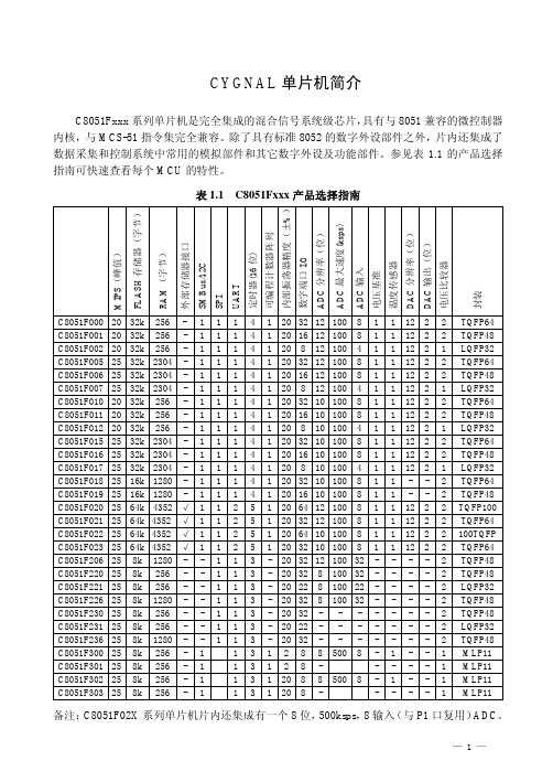
C8051F_全线产品选型手册
选型请启用筛选
Part Number C8051F000 C8051F001 C8051F002 C8051F005 C8051F006 C8051F007 C8051F010 C8051F011 C8051F012 C8051F015 C8051F016 C8051F017 C8051F018 C8051F019 C8051F020 C8051F021 C8051F022 C8051F023 C8051F040 C8051F041 C8051F042 C8051F043 C8051F044 C8051F045 C8051F046 C8051F047 C8051F060 C8051F061 C8051F062 C8051F063 C8051F064 C8051F065 C8051F066 C8051F067 C8051F120 C8051F121 C8051F122 C8051F123 C8051F124 C8051F125 C8051F126 C8051F127 C8051F130 C8051F131 C8051F132 C8051F133 C8051F206 C8051F220 C8051F221 C8051F226 C8051F230 C8051F231 C8051F236 C8051F300-GM C8051F300-GS C8051F301-GM C8051F301-GS C8051F302-GM C8051F302-GS C8051F303-GM C8051F303-GS C8051F304-GM C8051F304-GS C8051F305-GM C8051F305-GS C8051F310 C8051F311 C8051F312 C8051
C8051F单片机
5、系统复位
复位电路将控制器置于一个预定的缺省状态。 1)CIP-51 停止程序执行 2) 特殊功能寄存器(SFR)被初始化为所定义的复位值 3)外部端口引脚被置于一个已知状态 4)中断和定时器被禁止。 5)所有的SFR 都被初始化为预定值 6)I/O 端口锁存器的复位值为0xFF,全部为逻辑‘1’,内部 弱上拉有效,使外部I/O 引脚处于高电平状态。 7) MCU 使用内部振荡器运行在2MHz 作为默认的系统时钟。 8) 看门狗定时器被使能,使用其最长的超时时间。
13
1、概述
4、可编程数字I/O •C8051F310有29个I/O引脚(3个8位口和一个5位口) •C8051F31x端口的工作情况与标准8051相似,但有一些 改进。每个端口引脚都可以被配置为模拟输入或数字I/O 。 •被选择作为数字I/O的引脚还可以被配置为推挽或漏极 开路输出。 •在标准8051中固定的“弱上拉”可以被总体禁止,为低 功耗应用提供了进一步节电的能力。
18
3、优先权交叉开关配置
也称为“交叉开关”,按优先权顺序将端口0 – 3 的 引脚分配给器件上的数字外设(UART、SMBus、 PCA、定时器等)。 端口引脚的分配顺序是从P0.0 开始,可以一直分配 到P3.7。为数字外设分配端口引脚的优先权顺序为 UART0具有最高优先权,而CNVSTR具有最低优先 权。 优先权交叉开关的配置是通过3个特殊功能寄存器 XBR0、XBR1、XBR2来实现的,对应使能位被设置 为逻辑‘1’时,交叉开关将端口引脚分配给外设。
◆16K 字节可在系统编程的FLASH 存储器
◆1280字节的片内RAM ◆可寻址64K字节地址空间的外部数据存储器接口
◆硬件实现的SPI、SMBus/ I2C 和两个UART 串行接口
8051与C8051区别

C8051F020与80C51单片机的异同点作者:佚名来源:不详录入:Admin更新时间:2008-8-19 13:36:06点击数:64【字体:】1 引言80C51系列单片机及其衍生产品在我国乃至全世界范围获得了非常广泛的应用。
单片机领域的大部分工作人员都熟悉80C51单片机,各大专院校都采用80C51系列单片机作为教学模型。
随着单片机的不断发展,市场上出现了很多高速、高性能的新型单片机,基于标准8051内核的单片机正面临着退出市场的境地。
为此,一些半导体公司开始对传统8051内核进行大的构造,主要是提高速度和增加片内模拟和数字外设,以期大幅度提高单片机的整体性能。
其中美国Cygnal公司推出的C8051F系列单片机把80C51系列单片机从MCU时代推向SoC时代,使得以8051为内核的单片机上了一个新的台阶。
C8051F系列单片机是完全集成的混合信号系统级芯片,具有与8051兼容的CIP-51微控制器内核,采用流水线结构,单周期指令运行速度是8051的12倍,全指令集运行速度是原来的9.5倍。
熟悉NCS-51系列单片机的工程技术人员可以很容易地掌握C8051F的应用技术并能进行软件的移植。
但是不能将8051的程序完全照搬的应用于C8051F单片机中,这是因为两者的内部资源存在较大的差异,必须经过加工才能予以使用。
其中C8051F020以其功能较全面,应用较广泛的特点成为C8051F的代表性产品,其性能价格比在目前应用领域也极具竞争力。
C8051F020的内部电路包括CIP-51微控制器内核及RAM、ROM、I/O口、定时/计数器、ADC、DAC、PCA、SPI和SMBus 等部件,即把计算机的基本组成单元以及模拟和数字外设集成在一个芯片上,构成一个完整的片上系统(SoC)。
本文将介绍C8051F020单片机与80C51的异同点(主要是不同之处)及初学者编程时应该注意的问题,并给出经过Cygnal 开发工具IDE调试环境软件验证的源程序。
C8051F单片机简介
C8051F021 25 64k 4352 √ 1 1 2 5 1 20 32 12 100 8 1 1 12 2 2 TQFP64
C8051F022 25 64k 4352 √ 1 1 2 5 1 20 64 10 100 8 1 1 12 2 2 100TQFP C8051F023 25 64k 4352 √ 1 1 2 5 1 20 32 10 100 8 1 1 12 2 2 TQFP64
C8051F005 25 32k 2304 - 1 1 1 4 1 20 32 12 100 8 1 1 12 2 2 TQFP64
C8051F006 25 32k 2304 - 1 1 1 4 1 20 16 12 100 8 1 1 12 2 2 TQFP48
C8051F007 25 32k 2304 - 1 1 1 4 1 20 8 12 100 4 1 1 12 2 1 LQFP32
C8051F226 25 8k 1280 - - 1 1 3 - 20 32 8 100 32 - - - - 2 TQFP48
C8051F230 25 8k 256 - - 1 1 3 - 20 32 - - - - - - - 2 TQFP48
C8051F231 25 8k 256 - - 1 1 3 - 20 22 - - - - - - - 2 LQFP32
I2C_C8051_c8051F串口

//----------------------------------------------------------------------i2c_stop(); return temp; //stop the device
158. //--------------------------------------------
105. } 106. //---------------------------------------107. void i2c_write_byte(uchar dev_addr_wr,uchar word_addr,uchar mydata) 108. { 109. 110. 111. 112. 113. 114. } 115. //---------------------------------------116. uchar 117. { 118. 119. 120. 121. 122. 123. 124. 125. 126. 127. 128. 129. 130. 131. 132. uchar temp,i; temp=0xff; //--------------i2c_start(); i2c_send_byte(dev_addr_wr); i2c_send_byte(word_addr); i2c_stop(); //inital the address of device and word i2c_read_byte(uchar dev_addr_wr,uchar dev_addr_rd,uchar word_addr) i2c_start(); i2c_send_byte(dev_addr_wr); i2c_send_byte(word_addr); i2c_send_byte(mydata); i2c_stop();
C8051F系列

C8051F系列[编辑本段]C8051F系列CygnalC8051F(已被Silicon Lab收购)系列单片机是真正能独立工作的片上系统SOCCPU有效地管理模拟和数字外设可以关闭单个或全部外设以节省功耗FLASH存储器还具有在系线重新编程的能力即可用作程序存储器又可用作于非易失性数据存储应用程序可以使用MOVC和MOVX指令对FLASH进行读或改写。
一.Cygnal C8051F系列单片机特点1.片内资源8~12位多通道ADC1~2路12位DAC1~2路电压比较器内部或外部电压基准内置温度传感器±316位可编程定时/计数器阵列PCA可用于PWM等3~5个通用16位定时器8~64个通用I/O口带有I2C/SMBusSPI1~2个UART多类型串行总线8~64K Flash存贮器256~4K数据存贮器RAM片内时钟源内置电源监测看门狗定时器2.主要特点高速的20MIPS~25MIPS与8051全兼容的CIP51内核内部Flash存贮器可实现在系统编程即可作程序存贮器也可作非易失性数据存贮工作电压为2.7V~3.6V典型值为3VI/ORSTJTAG引脚均允许5V电压输入全系列均为工业级芯片-45℃~+85℃片内JTAG仿真电路提供全速的电路内仿真不占用片内用户资源支持断点单步观察点运行和停止等调试命令支持存贮器和寄存器校验和修改二.有关C8051F系列CPU1.与标准8051完全兼容Cygnal C8051F系列单片机采用CIP51内核Cygnal专利与MCS51指令系统全兼容可用标准的ASM51Keil C高级语言开发编译C8051F系列单片机的程序2.高速指令处理能力标准的8051一个机器周期要占用12个系统时钟周期执行一条指令最少要一个机器周期CygnalC8051F系列单片机指令处理采用流水线结构机器周期由标准的12个系统时钟周期降为1个系统时钟周期指令处理能力比MCS51大大提高CIP-51内核70% 的指令执行是在一个或两个系统时钟周期内完成只有四条指令的执行需4个以上时钟周期CIP-51指令与MCS51指令系统全兼容共有111条指令3.增加了中断源标准的8051只有7个中断源Cygnal C8051F系列单片机扩展了中断处理这对于时实多任务系统的处理是很重要的扩展的中断系统向CIP-51提供22个中断源允许大量的模拟和数字外设中断一个中断处理需要较少的CPU干预却有更高的执行效率4.增加了复位源标准的8051只有外部引脚复位Cygnal C8051F系列单片机增加了7种复位源使系统的可靠性大大提高每个复位源都可以由用户用软件禁止1 片内电源监视2 WDT看门狗定时器3 时钟丢失检测器4 比较器0输出电平检测5 软件强制复位6 CNVSTRAD转换启动7 外部引脚RST复位可双向复位8 提供内部时钟源标准的8051只有外部时钟Cygnal C8051F系列单片机有内部独立的时钟源C8 051F300/F302提供的内部时钟误差在2%以内在系统复位时默认内部时钟如果需要可接外部时钟并可在程序运行时实现内外部时钟的切换外部时钟可以是晶体RCC或外部时钟以上的功能在低功耗应用系统中非常有用。
- 1、下载文档前请自行甄别文档内容的完整性,平台不提供额外的编辑、内容补充、找答案等附加服务。
- 2、"仅部分预览"的文档,不可在线预览部分如存在完整性等问题,可反馈申请退款(可完整预览的文档不适用该条件!)。
- 3、如文档侵犯您的权益,请联系客服反馈,我们会尽快为您处理(人工客服工作时间:9:00-18:30)。
制造商Silicon Laboratories
RoHS否
数据总线宽度8 bit
程序存储器类型Flash
程序存储器大小128 KB
数据RAM 大小8.25 KB
接口类型I2C, SMBus, SPI, UART
最大时钟频率50 MHz
可编程输入/输出端数量32
定时器数量16 bit
工作电源电压2.7 V to 3.6 V
最大工作温度+ 85 C
安装风格SMD/SMT
封装/ 箱体TQFP-64
封装Tray
最小工作温度- 40 C
片上ADC12 bit
片上DAC12 bit, 2 Channel
Standard Pack Qty160
C8051F125/C8051F126/C8051F127和C8051F13x 系列器件是完全集成的混合信号片上系统型M
CU 芯片,具有64 个数
字I/O 引脚(100 脚TQFP 封装)或32 个数字I/O 引脚(64 脚TQFP 封装)。
下面列出了一些主
要特
性;有关某一产品的具体特性参见表1.1。
高速、流水线结构的8051 兼容的CIP-51 内核(100MIPS 或50MIPS)
全速、非侵入式的在系统调试接口(片内)
真正12 位或10 位、100 ksps 的ADC,带PGA 和8 通道模拟多路开关真正8 位500 ksps 的ADC,带PGA 和8 通道模拟多路开关(仅C8051F12x)
两个12 位DAC,具有可编程数据更新方式(仅C8051F12x)
2 周期的16 x 16 乘法和累加引擎(仅C8051F120/1/2/
3 和C8051F130/1/2/3)
128KK 或64KB 可在系统编程的FLASH 存储器
8448(8K+256)字节的片内RAM
可寻址64KB 地址空间的外部数据存储器接口
硬件实现的SPI、SMBus/ I2C 和两个UART 串行接口
5 个通用的1
6 位定时器
具有6 个捕捉/比较模块的可编程计数器/定时器阵列
片内看门狗定时器、VDD 监视器和温度传感器
具有片内VDD 监视器、看门狗定时器和时钟振荡器的C8051F12x 和C8051F13x 器件是真正能独立工作的片上系统。
所有模拟和数字外设均可由用户固件使能/禁止和配置。
FLASH 存储器还具有在系统重新编程能力,可用于非易失性数据存储,并允许现场更新8051 固件。
片内JTAG 调试电路允许使用安装在最终应用系统上的产品MCU 进行非侵入式(不占用片内资源)、全速、在系统调试。
该调试系统支持观察和修改存储器和寄存器,支持断点、观察点、单步及运行和停机命令。
在使用JTAG 调试时,所有的模拟和数字外设都可全功能运行。
每个MCU 都可在工业温度范围(-45℃到+85℃)工作。
端口I/O、/RST 和JTAG 引脚都容许
5V 的输入信号电压。
有100 脚TQFP 封装和64 脚TQFP 封装。
表1.1 列出了每个器件的特性和封装。
图1.1 ~ 图1.6 给出了每种器件的功能框图。