14065液压系统说明书C版
辊压机说明书
CLF140-65 压机安装、使用、维护说明书版本号:E编写人:尹红、陈雷、刘忠安审核人:徐智平中国成都市利君实业有限责任公司1・前言该说明书将使用户熟悉银压机及其辅助设备的安装、操作和维护。
在安装或操作辗压机前请仔细通篇阅读该说明书。
车昆压机釆用优质材料及高质量的制造技术使该机操作简便、结构合理、利于保养和检测。
如有任何问题,请拨电话、来传真或直接给本公司来函。
联系方式:地址:中华人民共和国四川省成都市武科东二路5号邮政编码:610045国际工程部:(国外用户联系)电话(传真):电子邮箱:技术服务部:(国内用户联系)电子邮箱:1. 1主要用途CLF系列規压机是在二十世纪末研制、开发的最新一代水泥工业专用粉磨设备,它能在极低能源消耗和运行成本下,实现水泥生料和水泥成品产量的大幅度提高。
在传统水泥生产过程中,粉磨电耗占总电耗的6 0 — 7 0 %,粉磨高能耗是水泥工业的老大难问题,严重阻碍着水泥企业经济效益的提升和水泥生产规模的大型化。
在粉磨系统中釆用基于料层粉磨技术的辗压机及配套的集打散、分级、烘干于一体的VXS或VXR选粉机,可与球磨机配合或自成系统组成各种各样的工艺流程,如预粉磨、混合粉磨、半终粉磨及终粉磨等系统。
由于粉磨机理的改变, 车昆压机及其系统工艺技术可使粉磨系统电耗降低20 — 100%,产量提高25-200%;适用于新建厂或老厂改造中的水泥生料或熟料的粉磨系统。
以丰昆压机为代表的料层粉磨技术和配套工艺必将成为新世纪水泥干法生产技术发展的新亮点和新热点。
1. 2工作原理CLF系列辘压机主要由电动机、行星减速器、耗系、机架、扭矩支承、液压加压装置、润滑装置、喂料装置、车昆罩、控制系统等组成,眾压机的两个辘轴分别由电动机经万向联轴器、行星减速机带动。
行星减速机安装在扭矩支承上,与车昆子间用缩紧盘联接。
车昆系分为活动车昆系和固定辘系,两个辘系都安装在机架上, 活动车昆系可在机架导轨上作水平运动,活动车昆系两端共有两个(或四个)平行油缸对辘系的轴承座施加压力,该压力通过车昆系作用在通过两车昆轴间的物料上,使物料被破碎、粉磨,并最终被压成料饼。
14065液压系统说明书C版
辊压机运行过程中,当活动辊两端间隙发生变化,需要调节时,根据控制程序发 出的信号,液压站及组合控制阀块相关控制阀门动作,对液压缸压力进行加压或减压 调节,从而调整活动辊的位置,对活动辊辊隙进行纠偏调整。当活动辊纠偏完成后, 恢复保压运行工况。
组合控制阀块上设置有安全溢流阀,可对液压缸的工作压力进行限制。当液压缸 内压力达到设计最高压力时,组合控制阀块上的多功能阀组动作,可在极短时间内, 将液压缸的工作压力卸压。
2
CLF14065 辊压机液压系统使用说明书
二、主要技术参数:
1. 液压站型号: 2. 液压站额定压力: 3. 液压泵额定流量: 4. 电机功率: 5. 过滤精度: 6. 液压缸活塞直径: 7. 液压缸活塞杆直径: 8. 工作行程: 9. 使用介质: 10. 油箱容积: 11. 重量:
1
CLF14065 辊压机液压系统使用说明书
一、概述:
辊压机在运行过程中,物料通过固定辊与活动辊之间时,在两辊的压力作用下而 被挤碎。在物料被压辊挤压的过程中,物料对压辊的反作用力将会使辊压机活动辊产 生回退力,向活动辊上施压并维持固定辊与活动辊之间的辊隙稳定是由液压控制系统 完成的。
对活动辊两端施压,由配置于辊压机本体上的四个液压缸进行,每两个液压缸为 一组,两组液压缸分别置于活动辊两侧,对称装配在端部件上。液压缸施压于活动辊 两侧轴承座上,从而传递到两辊之间的物料上。每组液压缸的压力控制各由一个组合 控制阀块控制,组合控制阀块安装在辊压机活动辊侧端部件上。组合控制阀块主要由 集成块、蓄能器、电磁换向阀、节流阀、单向阀、溢流阀、压力传感器、快速卸荷阀 组及测压接头组成。液压缸内液压油的补充及排泄,均由组合控制阀块上相关液压元 器件进行控制。
CRIMPX D160-T420 D165-T420系列液压软管压接机操作手册说明书
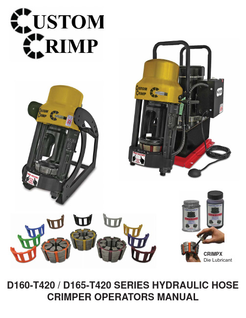
CRIMPXDie Lubricant D160-T420 / D165-T420 SERIES HYDRAULIC HOSE CRIMPER OPERATORS MANUAL•READ INSTRUCTIONS AND IDENTIFY ALL COMPONENT PARTS BEFOREUSING CRIMPER• CRIMPER CAN PRODUCE 60 TONS OF FORCE. KEEP BOTH HANDS AWAYFROM PINCH POINTS• CONSULT HOSE AND FITTING MANUFACTURER FOR CORRECT MACHINESETTINGS AND CRIMP MEASUREMENTS• ALWAYS WEAR EYE PROTECTIONSAFETY PRECAUTIONSMODELS COVEREDThis manual is applicable to different variations of the D160-T420 Series and D165-T420 Series Crimpers.Crimping, calibration and repair procedures are similar for all models.For Parts and Service, Contact:Custom Machining Services, Inc.Valparaiso, In 46383(219) 462-6128Small Footprint forminimum use of spacePowerful 62 TonHydraulic CylinderAdjustable Retraction StopT420 Rubber CagedDie SeriesRemovable PusherEasy AdjustableT420 Micrometer10-¼"17"18-½"Technical Data62 Ton1-¼" - 1 - 2 Wire1-¼" - 4SPL: 17" x W: 10-¼" x H: 18-½"Weight: 85 lbsMicrometer Style Adjustment: T420Die Series: T420 Rubber CagedHand PumpPneumatic PumpMulti-Electric PumpAvailablePumps:Adjustable Calibration ScrewCustomCrimp® QR CodeHigh strength frame for betterstability and performanceDie Orientation DecalT420 Pressure PlateT420 Pressure PlatePowerful 62 TonHydraulic Cylinder1HP/110V/Single Phasepump for fast crimpsMain Power SwitchElectrical EnclosureReservoirPneumatic Pendent SwitchRemovable PusherT420 Rubber CagedDie Series13"22-½"22-½"AdjustableRetraction StopT420 MicrometerFully AdjustableElectronic Shut OffD165-T42062 Ton1-¼" - 1 - 2 Wire1-¼" - 4SPL: 22-½" x W: 13" x H: 22-½"Weight: 154 lbsPower: 1HP/110V/1Phase (Standard)2HP/220V/1Phase (Optional)Micrometer Style Adjustment: T420Die series: D160-T420 Rubber CagedReservoir capacity: 1 US GallonOil type: ISO 46 Hydraulic OilSmall Footprint forminimum use of spaceCustomCrimp® QR CodeDie Orientation DecalFlexible 24" Work Lamp (Optional) P/N:1668-02For D165-T420 SeriesD165 Coupling Stop(Included) P/N:100954Die Storage Drawer (Optional) P/N:104650Dies sold separatelyCrimper shown mounted onthe Die Storage DrawerPneumatic Pendent Switch(Included) P/N:101349ValPower ® Hand Pump 10,000 psi (Optional)P/N:VHP-10-43ValPower ® Pneumatic Pump10,000 psi (Optional)P/N:VAP-10-100T420 Micrometer (Included)P/N:103085ValPower ® Multi-Electric Pump(Optional)CRIMPX Die Lubricant: Grease 4 oz can with brush(Available) P/N:104162T420/D Series Die Removal Magnet(Included) P/N:104679Die Storage Shelf(Optional) P/N:101431CRIMPX Die Lubricant: Oil 4 oz bottle with dauber cap(Included) P/N:103886T420 MICROMETER• Plug the D165-T420 crimper directly into a 110 volt wall outlet. CAUTION: DO NOT RUN THE CRIMPER ON AN EXTENSIONCORD AS LOW VOLTAGE CAN DAMAGE THE MOTOR.• Oil level in the D165-T420 pump should be 1-1/2 to 2 inches below the fi ll plug and should be visible in the sight glass window of the pump reservoir• Check to be certain that the shipping plug in the pump reservoir has been replaced with the Oil Fill and Vent Plug shipped with the crimper.• Place any Die Set and the Pressure Plate in the crimper bottom fl ange in the order shown. (A hose and fi tting are not required for a calibration check)• Lubricate the die set as shown in Crimping Instructions.NOTE: FAILURE TO LUBRICATE THE DIE SET AND COMPRESSIONCONE COULD RESULT IN THE DIE SET SEIZING IN THE COMPRESSION CONE .• Slide the Pusher onto the stud on the hydraulic cylinder.• Set the Micrometer at “0”.• Depress and hold the Start/Stop switch on the D165-T420 Series or continue to apply pressure to the D160-T420 Series until the Die set is completely closed and oil pressure has built up in the hydrau-lic cylinder.• For the D165-T420 Series: If the ram extends and shuts off the motor approximately 1 second after the die fi ngers are completely closed and the pump builds pressure (The sound of the pump will change) the crimper is correctly calibrated.• For the D160-T420 Series: If the micro site indicator (white line) is just visible as shown in the il-lustration after the dies are completely closed and pressure has built up in the hydraulic cylinder the crimper is correctly calibrated.• If the above conditions are not met, the crimper must be recalibrated. See calibration instructions on P 10.FOLLOW THESE STEPS BEFORE USING THE CRIMPER FOR THE FIRST TIMEMicro site IndicatorPhoto # 1Photo # 2Grease Point # 1Place a thin layer of CrimpX oil (supplied with crimper) or a high pressure molybdenum high pressure grease on the surface of the bottom fl ange (as shown in photo # 1).Grease Point # 2Before sliding the pressure plate or the notched pressure plate over the correct dies, place a thin layer of CrimpX oil (supplied with crimper) or a high pressure molybdenum high pressure grease on the entire area that dies come in contact with (as shown in photo # 2).If Dies are sticking in the surface of the bottom fl ange: Continue to lubricate / grease as explained above in addition to lubricating each die fi nger individually (as shown in photo # 3).Note: The die fi ngers must be lubricated at both positions that come in contact with the pressure plate and the bottom flange.Make certain that the cone base is clean and lubricated prior to inserting the die set.Select the correct die set for the hose-fi tting combination from the manufacturers speci fication sheet. Lubricate the die fi ngers withCrimpX Oil furnished with the crimper.Place the lubricated die set squarely in the cone base as shown.Align the fi tting in the die set according to the hose and fi tting manufacturers recommendation.Place the Compression Plate over the die set and compress the die set by hand to hold the hose and fi tting in place. See micrometer setting example .Slide the Pusher onto the stud on the ram and press the start stop switch or apply pressure to the D160-T420 series. The crimper will shut off when the crimp cycle is complete.When the crimp is complete in the D160-T420 series, a white indicator line will be visible.Check the fi nal crimp diameter to con fi rm that it is within manufacturers speci fications.Micrometer Setting Example: With a 30mm die and the micrometer set at 3.0mm, the fi nal crimpdiameter will be 33mm (30mm + 3mm)Make certain that the cone base is clean and lubricated prior to inserting the die set.Select the correct die set for the hose-fi tting combination from the manufacturers speci fi cation sheetLubricate the die fi ngers withCrimpX Oil furnished withthe crimper.Check the fi nal crimp diameter to con fi rm that it is withinAlign the fi tting in the die set according to the hose and fi ttingmanufacturers recommendation.Place the Notched Pressure Plate over the dies so that the notched compression plate is covering all 8 die fi ngers (as shown).Place the pusher onto the retaining ringas shown. Once the correct micrometer setting is set press the start/stop switch. (Apply pressure on D160-T420 series).Place the lubricated die set squarely in the cone base as shown. Make sure the split of the die cages is facing the operator (as shown).1. Die split must face operator.2. Notched Pressure Plate needs to cover all 8 die fi ngers.3. Damage can occur to die fi ngers if parts aren’t aligned properly.Wrong AlignmentBroken Die Finger• Insert any die set and the Compression Plate in the cone base as shown. Note: There should not be a fi tting in the die set when checking calibration.• Set the Micro Crimp Adjuster as follows at “0”.• Slide the Pusher onto the stud of the hydraulic ram.• Press and hold the start/stop switch until the crimper shuts off for theD165-T420 or apply pressure to the D160-T420 Series until the die set is completely closed and the white indicator on the Micro Sight button is just visible.• If the D165-T420 motor shuts off in approximately 1 second after the dieset is fully closed or the white line on the Micro Sight button is just visible,the crimper is correctly calibrated.• If the crimper requires recalibration, hold the micrometer barrel with a 5/16 inch open end wrench and rotate the stem either in or out with a 5/32 inch hex key wrench.• Rotating the stem out of the barrel decrease the time required for the pump to shut off.• Recheck calibration.Install (2) 3/8-16 x 1" carriage bolts in front twoholes (as shown in picture # 1). Use 3/8" plasticretaining washer to hold bolt into place.Slide the drawer slightly out to access two rear holes(as shown in picture # 2). Install (2) 3/8-16 x 1" carriagebolts in rear two holes (as shown in picture # 2). Use3/8" plastic retaining washer to hold bolt into place.Place the D105/D165 base plate over the 4screws as shown in picture # 3.Place 3/8" fl at washer, 3/8" locking washer, andthen the 3/8"- 16 nut over the bolt as shown. Tighten each nut with a 9/16" wrench or socket until the nuts are tight as shown in picture # 4.Note: Bolt the D105/D165 crimper drawer assembly /# 1# 3# 4# 2PROBLEM: CRIMPER WILL NOT RUN AT ALL• The white rocker switch is also a circuit breaker. Check to see that the circuit breaker has not been tripped• Check the wall outlet. The crimper comes from the factory wired for a 115 volt single phase circuit. Use of extension cords or outlets with inadequate power can damage the motor . Do not run the crimper from a portable power source.• Check the stop switch mounted to the switch bracket under the Micro-Crimp Adjuster. This is a normally closed switch and if it does not close the crimper will not operate.CAUTION: Do not operate the crimper with this switch jumpered as the pump will not shut off and the bracketscan be damaged.• Check the pneumatically actuated switch in the electrical box mounted on the motor. This switch controls power to the mo-tor and is actuated with air pressure from the pendant switch bulb.PROBLEM: CRIMP DIAMETER TOO LARGE• Incorrect setting of the Micro-Crimp Adjuster. Check crimp specifi cations.(NOTE: All published machine settings are approximate. To correct for slight variances, the gauge settings may need to be adjusted for the specifi c hose, fi tting and size combination.)• Incorrect die being used. Each die has a useable range of approximately 3mm (.120 in) above the closed diameter of the die.The closed diameter is the die size stamped on the die ring.• Check crimper calibration and re-calibrate if required.• Inadequate pump pressure. Check oil level in the pump. It should be 1-1/2 to 2 inches below the fi ll plug and should be showing in the sight glass window. Fill with ISO 46 weight hydraulic oil if required.• Inadequate lubrication of the dies and compression ring causing the pump to work harder than normal to reach the required diameter. Use only the grease shipped with the machine or equivalent.• Inadequate pressure being generated by the pump. This is most likely if the crimper can crimp the smaller size hoses and not the larger hoses. When correctly adjusted, the pump should generate approximately 10,000 psi.Do Not adjust pump to produce in excess of 10,000 psi as damage to components or personal injury may result.• No pressure being generated by the pump. There should be a defi nite change in pitch of the pump as it cycles into high pres-sure mode and begins to “work” harder.PROBLEM: CRIMP DIAMETER TOO SMALL• Incorrect setting of the Micro-Crimp Adjuster. Check crimp specifi cations.( NOTE: All published machine settings are approximate. To correct for slight variances, the gauge settings may be adjusted for the specifi c hose, fi tting and size combination.)• Incorrect die being used (See die range under Crimp Diameter too Large)• Check crimp diameter and re-calibrate if necessaryPROBLEM: DIES STICKING IN COMPRESSION CONE• Inadequate lubrication of the compression cone and die surfaces. Use only the grease shipped with the machine or equivalent.CustomCrimp® “No-Nonsense” Warranty StatementAll CustomCrimp® Products are warranted to be free of defects in workmanship and materials for one year from the date of installation. This warranty ends when the product becomes unusable for reasons other than defects in workmanship or material.Any CustomCrimp® Product proven to be defective in workmanship or material will be repaired or replaced at no charge. To obtain benefi ts of this warranty, fi rst, contact Warranty Repair Department at Custom Machining Services at (219) 462-6128 and then deliver via prepaid transportation the complete hydraulic product to:ATTN: WARRANTY REPAIR DEPT.Custom Machining Services, Inc.326 North Co. Rd 400 EastValparaiso IN 46383If any product or part manufactured by CustomCrimp® is found to be defective by CustomCrimp®, at its option, CustomCrimp® will either repair or replace the defective part or product and return via ground transportation, freight prepaid.CustomCrimp® will not cover any incoming or outgoing freight charges for machines sold outside The United States.This warranty does not cover any product or part which is worn out, abused, altered, used for a purpose other than for which it was intended, or used in a manner which was inconsistent with any instructions regarding its use.Electric motors are separately warranted by their manufacturer under the conditions stated in their separate warranty.See the complete line of CustomCrimp ® Crimpers and Accessories at:(219) 462-6128CustomCrimp ® Custom Crimp ®Custom Machining Services, Inc.326 N. County Rd. 400 EastValparaiso, IN 46383Ph: (219) 462-6128Fax: (219) 464-2773。
水压试验机液压系统使用说明书

水压试验机液压系统使用说明书使用说明书连云港唯德复合材料设备有限公司目录一、概述二、系统工作原理及说明三、液压系统的使用注意事项四、特别说明五、液压缸故障原因及排除方法六、液压系统压力异常的故障及排除方法七、液压系统原理图八、配件表一、概述水压试验机液压系统是根据用户提供的要求和技术参数而设计的一种专为液压缸提供动力源的泵站机组装置。
它通过电机—油泵组将电能转化为液压能,并由液压阀控制系统的压力、流量、方向,操纵油缸完成设备所需要的各项作业。
二、系统工作原理及说明液压系统由液压泵站、顶升油缸及联接它们的高压管件组成。
较详细的构成见液压系统原理图。
手动换向阀的中位机能是Y,该换向阀处于中位,系统液压执行元件处于浮动状态,当系统与液控单向阀连接可以满足液压定位的不同要求,当换向阀手柄前推或后拉时,顶升油缸活塞杆伸出或缩进,从而实现顶升机构的上升或下降。
在液压系统中小车顶升油缸,经过分流集流阀的控制实现了顶升机构的同步升降;再配合液控单向阀、单向节流阀控制,最终实现油缸均速同步锁紧保压等功能。
溢流阀用于保护系统压力不至于超载,溢流阀出厂时已调好,不必要时,用户不得随意调整。
三、液压系统的使用注意事项1、液压油液压系统使用的液压油推荐使用:南方:N46抗磨液压油或30#液压油。
应注意保护工作油液的清洁度,加油前应通过滤油机(过滤精度100µm)加油,加油口位于油箱上盖板,并装有滤清器,应及时换油,一般情况下,累计工作1200小时应更换一次新油,使用过程中,液面最好位于油窗的中部,应经常拆洗,累计200小时拆洗一次,经多次清洗后、达不到过滤的作用时可更换滤芯。
2、电机的接线电机接线应使电机为顺时针方向旋转(俯视电机风叶应为顺时针方向旋转),若接错,泵不打油,该系统不能工作,且易损坏油泵。
3、系统排气若油缸或管路中混有空气,会出现油缸在顶升、回缩过程中出现爬行或抖动现象,因此在正式运行前需先空运转两次以上。
液压系统使用说明书范例
液压系统使用说明书范例使用说明书编制:审核:批准:时间:2003年月日目录1、综述2、技术数据3、系统结构及工作原理4、安装维护5、调试运行6、附图(略)1、综述本使用说明介绍了VKM5型混合锅液压系统的结构及功能,提供了设备正确操作所必需的相关知识。
本操作说明必需存放在合适的位置,以便操作人员随时取用。
设备投入使用之前,所有操作者必须仔细阅读本操作说明。
我们建议操作者应具备一定的液压知识。
保修期内,用户应将运行情况及完成的各项维修保养工作记入液压系统运行记录本中备查。
2、技术数据2.1、旋转回路2.1.1、最高工作压力:Pe =10MPa2.1.2、最大流量:Qe =9.9L/min2.1.3、马达排量:49.5ml/r;转速:10~200rpm、波动在±2.5%以内2.1.4、电动机参数:变频电机1.5KW/1440rpm/380V/50Hz2.2、升降回路2.2.1、最高工作压力:Pe =4MPa2.2.2、最大流量:Qe =5.8L/min2.2.3、油缸活塞杆运行速度:0.3~1.5m/min(一次调定),两个双作用油缸:油缸活塞直径:φ40mm,活塞杆直径φ25,油缸活塞行程:800mm2.2.4 电动机参数:1.1KW/960rpm/380V/50Hz2.3 油箱容积: V=150L2.4 液压油:N32(冬)/N46(夏),清洁度:ISO标准18/132.5冷却器:冷却水≤28℃、0.15~0.2MPa、20L/min3、系统结构该系统由四部分组成:旋转回路、升降回路、油箱总成及管路系统。
3.1、旋转回路由立式安装的泵电机组件、控制阀组、液压马达等组成。
其中油泵驱动电机为变频电机,由变频器对电机进行调速,使油泵按要求输出变化的流量,从而控制液压马达的输出转速。
3.2、升降回路由立式安装的泵电机组件、手摇泵、控制阀组、两个双作用油缸等组成。
手摇泵直接与油缸下腔相连,当出现突然停电事故时,能人工摇动手摇泵,使油缸上升至要求的位置。
FCS165用户手册

FSH01液压伺服模件用户手册版本号:V01中国华能集团公司技术中心第一章模件介绍综述FSH01 液压伺服模件是用于阀门位置控制的I/O 模件。
主处理器模件通过液压伺服模件控制电液伺服阀,进而控制液压执行机构。
液压伺服模件通过改变电液伺服阀线圈的电流,改变液压执行机构的行程位置。
线性可调差接变压器(LVDT)给液压伺服模件提供执行机构的行程位置反馈。
它的典型应用是控制蒸汽轮机的调节门、燃气轮机的燃料阀和挡板角度调节。
使用提示用户在安装、使用、维护液压伺服模件之前,应仔细阅读本手册。
模件的安装、调试、故障判断和更换,需要对电子线路、液压执行机构、电液伺服阀有操作经验的工程师来进行。
模件的操作、参数设定需要对汽轮机启动、电厂发电工艺流程有操作经验的工程师来进行。
模件简述FSH01 液压伺服模件是带嵌入式数字信号处理器的智能I/O 模件,它由四层印刷线路板和面板组成。
面板上有一个双色LED 、两个单色LED 模件状态指示灯。
它占用FCS165 系统模件安装单元的一个标准槽位。
模件应用FSH01 液压伺服模件为处理器模件提供对液压执行机构的电液伺服阀的驱动。
在大多数情况下,处理器模件配合使用FSD01测速模件、FSH01液压伺服模件完成汽轮机转速的精确闭环控制。
通过I/O总线接受处理器模件的阀门开度指令,输出相应电流驱动电液伺服阀、通过LVDT 自动检测阀门开度、实现汽轮机阀门开度的线型闭环控制,同时向处理器模件反馈阀门开度及状态信号。
模件主要功能及特点电液伺服阀驱动部分:双路±100mA伺服阀电流驱动输出,可驱动MOOG阀、I/H 转换器;驱动输出可设定为平衡位置输出微负电流,负电流为开阀门信号,正电流为关阀门信号。
采用电流驱动技术,对温度引起伺服阀线圈阻抗的变化不敏感。
冗余的伺服阀输出可选择双路伺服阀控制或单阀控制,一路备用。
●防卡瑟功能:可选择叠加频率、幅值可调的Dither信号(通过软件参数设置),防止油动机卡瑟。
液压自动涨紧系统使用说明书

液压自动涨紧系统使用说明书首先检查油泵电机转向,方法是:按一下“电机启动按钮”,“电机运行”指示灯亮,电机运转,此时应仔细观察电机转向是否与要求一致,若不一致应迅速按下“电机停止按钮”使电机停转,然后通过变换电源或电机接线进行调整(调整时应注意一定要先将控制箱进线电源切断以确保安全)电机转向调整好后,将控制箱重新送电并按下“电机启动按钮”使电机运转,电机运转平稳后将液压站上的四个截止阀全部打开,将控制箱上的“油缸回缩开关”打在关的位置,然后慢慢调整调节旋钮1和2,此时压力表1(油泵压力)和压力表2(蓄能器压力)应有压力指示,然后继续调整两个旋钮直至压力表1和2的指示压力一致为止。
随着油泵运转,表1和2压力会逐渐升高,当表1和2的压力升高到190bar时油泵电机自动停止(高压保护)。
此时应仔细检查整个液压站看有无漏油现象,若有应及时处理。
检查完毕,顺时针调整液压站上的减压阀调整螺栓,此时压力表3(油缸压力)有压力指示并逐渐升高,同时张紧油缸活塞杆慢慢升出,压力表2的压力逐渐下降(此时压力表1无压力指示)。
调整过程中,若压力表2的压力降到120bar 以下油泵电机将自动启动补压力,最后压力表3的压力调整在100bar(链条的张紧压力)。
张紧压力调整好后要仔细检查油缸及连接管路,一定要保证无泄漏现象。
捞渣机运行过程中,张紧压力不合适可适当进行调整(顺时针调整减压阀调节螺栓,张紧压力增大;逆时针调整减压阀压力减小)。
捞渣机因检修或其它原因不需张紧链条时可将控制箱上的“油缸回缩开关”打在开的位置,此时油缸会很快回缩到初试位置。
自动张紧系统在正常运行过程中,若因管道泄漏或其他原因使系统压力低于100bar或油缸压力低于40bar时,系统将向渣系统PLC发出“系统压力低”,报警信号,以提醒运行人员及时处理以确保设备运行安全。
自动张紧系统在正常运行过程,若系统压力高于210bar溢流阀将自动打开泄压,以确保整个系统及人身安全。
C140汽轮机说明书
使用说明书目录1、主要技术规范--------------------------------22、汽轮机的结构与性能--------------------------43、主要安装数据--------------------------------94、螺栓热紧说明--------------------------------195、汽轮机启动、运行与维护----------------------226、标志、包装、保管、运输----------------------327、汽轮机用油规范-------------------------------33使用说明书1、主要技术规范1.1 汽轮机型号C140-8.83/0.8831.2 汽轮机型式高压双缸、冲动、单抽汽凝汽式1.3 调节方式喷嘴调节1.4 额定功率140000KW1.5 最大功率155000KW1.6 纯冷凝额定功率140237KW1.7 转速3000r/min1.8转子旋转方向从机头看为顺时针1.8 工作电网频率50HZ1.10 蒸汽初压8.83MPa1.11 蒸汽初温535℃1.12 抽汽压力(额定工况) 0.883MPa1.13 抽汽压力调整范围0.686~1.176MPa1.14 额定工况排汽压力0.0051MPa1.15 纯凝汽工况排汽压力0.0053MPa1.16 冷却水温20℃(最高33℃)冷却水量22000t/h1.17 额定工况给水温度220℃1.18 纯冷凝工况给水温度219.5℃使用说明书1.19 额定工况进汽量578t/h1.20 最大工况进汽量660t/h1.21 纯凝汽工况进汽量505t/h1.22 额定工况抽汽量80t/h1.23 最大抽汽量200t/h1.24 汽缸数21.25 高压部分级数1单列调节级+15压力级1.26 低压部分级数2×5压力级1.27额定工况汽耗 4.128kg/kw.h1.28额定工况热耗8637.7kJ/kw.h1.29纯凝汽工况汽耗 3.601kg/kw.h1.30凝汽工况热耗9104.7kJ/kw.h1.31汽轮机总长14.848m1.32汽轮机外形尺寸(长×宽×高)14.848×6.72×3.775m 1.33回热抽汽数7级1.34高压加热器2台1.35高压除氧器1台1.36低压加热器4台1.37凝汽器数(双排汽) 2台使用说明书2、汽轮机的结构与性能2.1 C140-8.83/0.883型汽轮机为高压、冲动、抽汽凝汽式汽轮机,双缸、单轴、两排汽,具有一级调整抽汽。
- 1、下载文档前请自行甄别文档内容的完整性,平台不提供额外的编辑、内容补充、找答案等附加服务。
- 2、"仅部分预览"的文档,不可在线预览部分如存在完整性等问题,可反馈申请退款(可完整预览的文档不适用该条件!)。
- 3、如文档侵犯您的权益,请联系客服反馈,我们会尽快为您处理(人工客服工作时间:9:00-18:30)。
四、电气控制及联锁:
1. 液压站油箱内液压油油位由一个液位控制器进行检测,设置为低位报警,延时 5 分 钟后,报警信号如未消除,将会发出辊压机停机报警信号。
2. 油箱内液压油温度由一个铂热电阻进行检测,当油温低于 25℃时,电加热器供电, 对油箱内液压油进行加热;当液压油温度达到 35℃时,电加热器断电。
组合控制阀块上设置有安全溢流阀,可对液压缸的工作压力进行限制。当液压缸 内压力达到设计最高压力时,组合控制阀块上的多功能阀组动作,可在极短时间内, 将液压缸的工作压力卸压。
2
CLF14065 辊压机液压系统使用说明书
二、主要技术参数:
1. 液压站型号: 2. 液压站额定压力: 3. 液压泵额定流量: 4. 电机功率: 5. 过滤精度: 6. 液压缸活塞直径: 7. 液压缸活塞杆直径: 8. 工作行程: 9. 使用介质: 10. 油箱容积: 11. 重量:
纸进行。 3. 液压油管的安装应符合相关标准。应注意管道、接头的清洁,不允许有脏物、油脂
或异物进入其中。仔细检查每根管道,必要时应在安装连接时吹拂干净。 4. 根据电气接线图,完成液压站电气组件的接线。当接线完毕、核查无误后,可根据
现场安装情况,向液压油站油箱内按要求加注液压油。液压油加注后,接通电加热 器及恒温控制装置的电源使油温在任何时间始终保持在工作温度范围内。 5. 液压系统的管道安装及检查,可参照《CLF14065 液压管道安装规范》进行。
辊压机液压系统是由本公司集成,液压站型号为 CLYYZ-8II,主要由油箱、液 压泵、电动机、高压过滤器、电加热器、冷却器、压力表、电磁换向阀、单向阀、溢 流阀等元器件组成,液压站提供液压缸工作压力。
辊压机运行过程中,当活动辊两端间隙发生变化,需要调节时,根据控制程序发 出的信号,液压站及组合控制阀块相关控制阀门动作,对液压缸压力进行加压或减压 调节,从而调整活动辊的位置,对活动辊辊隙进行纠偏调整。当活动辊纠偏完成后, 恢复保压运行工况。
1ห้องสมุดไป่ตู้
CLF14065 辊压机液压系统使用说明书
一、概述:
辊压机在运行过程中,物料通过固定辊与活动辊之间时,在两辊的压力作用下而 被挤碎。在物料被压辊挤压的过程中,物料对压辊的反作用力将会使辊压机活动辊产 生回退力,向活动辊上施压并维持固定辊与活动辊之间的辊隙稳定是由液压控制系统 完成的。
对活动辊两端施压,由配置于辊压机本体上的四个液压缸进行,每两个液压缸为 一组,两组液压缸分别置于活动辊两侧,对称装配在端部件上。液压缸施压于活动辊 两侧轴承座上,从而传递到两辊之间的物料上。每组液压缸的压力控制各由一个组合 控制阀块控制,组合控制阀块安装在辊压机活动辊侧端部件上。组合控制阀块主要由 集成块、蓄能器、电磁换向阀、节流阀、单向阀、溢流阀、压力传感器、快速卸荷阀 组及测压接头组成。液压缸内液压油的补充及排泄,均由组合控制阀块上相关液压元 器件进行控制。
3. 液压泵在运行中,如液压站油箱内油温达到 40℃时,应将液压站冷却器供水管路上 冷却水阀门打开,向冷却器供水冷却液压油。
4. 液压站运行一段时间后,当高压过滤器滤芯脏污,滤油压差达到设定值时,安装在 过滤器上的压差发讯器发出报警电气讯号,同时压差发讯器红色栓顶出,应在停机 时更换滤芯。
5. 每组液压缸活塞端压力,由组合控制阀块上的压力传感器进行检测,与安装在辊压 机本体上的位移传感器检测的辊隙,共同实现压力、位移联合检测控制。
组合控制阀块上设置的溢流阀 A、溢流阀 B(见图 21),对液压缸的最高工作压力 进行了限制。当液压缸活塞端压力超过安全溢流阀的设定压力值时,溢流阀开启卸压, 降低液压缸活塞端的压力。
组合控制阀块设置有快速卸压阀(见图 21,电磁换向阀 C),当主控程序发出快速
3
CLF14065 辊压机液压系统使用说明书
CLYYZ-8II 16 MPa 8 L/min 5.5 KW 10 µm Ø360 mm Ø280 mm 50 mm VG 68(VG46)抗磨液压油 400 L ~585 Kg
注意:VG46 为冬季使用的液压油牌号。
三、工作原理:
当液压站油位、油温正常,发出液压站启动备妥信号。启动液压泵,液压站低负荷 运行。当辊压机主控程序发出辊压机启动预备信号后,液压站上电磁换向阀通电,液压 站处于溢流运行状态;设置在辊压机上的组合控制阀块上的电磁换向阀 A(见图 21) 通电换向,向液压缸活塞端内注入液压油,液压缸内压力开始上升,当压力达到设定值 时,向主控程序发出液压系统备妥信号,液压泵转入低负荷运行。
CLF14065 辊压机液压系统 使用说明书
版本号:C 版
成都市利君实业有限责任公司
CLF14065 辊压机液压系统使用说明书
目录
目 录................................................................................................................................................1 一、概述:..............................................................................................................................................2 二、主要技术参数:..............................................................................................................................3 三、工作原理:......................................................................................................................................3 四、电气控制及联锁:..........................................................................................................................4 五、液压系统的安装:..........................................................................................................................4 六、操作说明:......................................................................................................................................5
1.概述:........................................................................................................................................5 2.液压系统初次运行: ................................................................................................................ 5 3.液压系统负荷运行操作说明: ................................................................................................ 6 七、液压系统维护、检修:..................................................................................................................7 1. 系统初期运行维护、检修:..................................................................................................7 2. 每周维护、检修:..................................................................................................................7 3. 液压站的检修..........................................................................................................................8 4. 组合控制阀块的检修............................................................................................................17 5. 阀件清洗注意事项................................................................................................................33
液压油温度,由本公司编制的自动控制程序进行检测、调控。 2.液压系统初次运行: 1) 确保液压站油箱内已按照要求加注适量液压油。向油箱内加注液压油时,电加热器
应确保处于断电状态。油箱内加注液压油时,必须通过空气滤清器向油箱内加注液 压油,液压油牌号为 VG68(冬季为 VG46)抗磨液压油。 2) 在依次启动液压系统运行前,必须确保辊子间间距已调整适当。两辊不能接触,且 两辊间或两辊上不允许有异物。辊压机上方进料口应盖严以防止异物进入压辊之 间。 3) 点动液压泵的电机,检查旋转方向是否正确。启动液压泵连续运转 10min,检查高 压过滤器滤油压差,如达到设定值,必须更换滤芯。完成上述步骤后,液压泵电机 断电停机。 警告:启动液压泵前,确认液压站高压球阀处于开启状态,关闭高压球阀会造成液 压泵损坏! 4) 检查所有压力连接管道是否安全可靠,是否有漏油的现象发生。 5) 蓄能器充氮: a) 蓄能器充氮气前,应放出蓄能器与压力管路连接处内残留的液压油。蓄能器充