CLVTH16501IDGGREP;中文规格书,Datasheet资料
DTG650用户手册说明书

V E R S A T I L I TY// DgT 650USER MANUAL//. . . . . . . . . . . . . . . . . . . . . . . . . . . . . . . . . . . . . . . . . . . . . . . . . . . . . . . . . . . . . . . . . . . . . . . . . . . . . . . . . . . . . . . . . . . . . . . . . . . . . . . . . . . . . . . . . . . . . . . . . . . . . . . . . . . . . . . . . . . . . . . . . . . . . . . . . . . . . . . . . . . . . . . . . . . . . . . . . . . . . . .. . . . . . . . . . . . . . . . . . . . . . . . . . . . . . . . . . . . . . . . . . . . . . . . . . . . . . . . . . . . . . . . . . . . . . . . . . . . . .. . . . . . . . . . . . . . . . . . . . . . . . . . . . . . . . . . . . . . . . . . . . . . . . . . . . . . . . . . . . . . . . . . . . . . . . . . . . . . . . . . . . . . . . .. . . . . . . . . . . . . . . . . . . . . . . . . . . . . . . . . . . . . . . . . . . . . . . . . . . . . . . . . . . . . . . . . . . . . . . . . . . . . . . . .. . . . . . . . . . . . . . . . . . . . . . . . . . . . . . . . . . . . . . . . . . . . . . . . . . . . . . . . . . . . . . . . . . . .. . . . . . . . . . . . . . . . . . . . . . . . . . . . . . . . . . . . . . . . . . . . . . . . . . . . . . . . . . . . . . . . . . . . . . . . . . . . . . . . . . . .. . . . . . . . . . . . . . . . . . . . . . . . . . . . . . . . . . . . . . . . . . . . . . . . . . . . . . . . . . . . . . . . . . . . . . . . . . . . .. . . . . . . . . . . . . . . . . . . . . . . . . . . . . . . . . . . . . . . . . . . . . . . . . . . . . . . . . . . . . . . . . . . . . . . . . . . . . . . . . . . . .. . . . . . . . . . . . . . . . . . . . . . . . . . . . . . . . . . . . . . . . . . . . . . . . . . . . . . . . . . . . . . . . . . . . . . .// IntroThank you for choosing a LEWITT DGT 650!In brief: It’s the most versatile USB microphone on the market. It’s compatible with Windows, Mac and even iOS devices. It can be used to record vocals, instruments, ambient sound, samples, podcasts and more, both mono with a cardioid polar pattern and stereo thanks to its XY capsule arrangement.Plug in and record your guitar, synthesizer, mixing desk or any other line output-equipped device via the brea-kout box. You can even plug any MIDI input device directly into your DGT 650’s own 5-pin MIDI jack ...You see, this is way more than a simple USB microphone: it’s your Digital Multi-T ool.// Features//XY stereo capsule arrangement for authentic recordings of any acoustic event// Switchable to cardioid polar pattern// Hi-Z stereo line-in (6.3 mm, ¼ inch) for directly connecting your instruments// Illuminated user interface for quick and easy handling even in dark environments//Streamlined cable handling due to our breakout box // Recording on the go with iPhone, iPod touch or iPad // Built in lithium-ion battery for mobile applications// Bus-powered on PC & Mac// 4 recording modes// MIDI support// Headphone amp// Zero-latency direct monitoring// Mixable direct monitoring and tape return signal for host device playback and zero-latency monitoring of the microphone// Asynchronus USB transfer: precise internal clock handles the samplerate timing to avoid jitter and ensure bit & pitch accurate audio reproduction // T op applications // Home studio and live recording// Mobile / outdoor recording// Sample and demo recording// Podcasts and YouTube productions// Recording ModesWe’ve built four different recording modes into your DGT 650 to make it the most versatile USB microphone in the world, serving you as a true digital multi-tool. Since we’ll need to refer to those different modes later on in this user manual (and because we think they’re really cool), we’d like to briefly introduce them to you here:XY Stereo Mode // Two cardioid capsules with 90° opening for XY stereo recording. Use this mode for recor-ding live concerts, band rehearsals, ambient sounds, background vocals and for similar applications where you want to capture the room sound and the stereo image of any acoustic event.Cardioid Mode // The two capsules are mixed together to create a cardioid pattern. Best used for vocal recor-ding or other applications where you need good rear and side rejection.Singer/Songwriter Mode // Channel 1 is the cardioid mic and channel 2 is the line input. Use this mode for simultaneous recording of acoustic and line sources. For example: plug in your guitar to the line input and sing into the microphone to put the two signals on separate tracks. If you plug a stereo source into the line input, it will be summed mono (this could possibly cause phase issues on some synthesizers).Stereo Line-In Mode // Used to capture a stereo line signal. Connect a synthesizer or mixing console output and record it directly to your device.// SetupConnect the breakout box to the lockable hi-speed 18-pin data connector (11) of the microphone, then connect the USB cable to the computer or the lightning connector (sold separately) to your iOS device. If you need to extend the USB cable, be sure to use a HI-SPEED-compatible USB extension cord. We do not recommend the use of USB hubs, but if you need to, only use a powered hub or use the dedicated charging port to power the DGT 650.OS X (10 .6 and up) //Connect the DGT 650 to the breakout box and the breakout box to the USB port.Open “system preferences” in the menu at the top of the screen.Click on the “Sound” icon.Click the “Output” tab and select “DGT 650.”Click the “Input” tab and also select the “DGT 650.”windows //Connect the DGT 650 to the breakout box and the breakout box to the USB port.Download and install the drivers – please follow the onscreen instructions.T o use the DGT 650 with your preferred sequencer / digital audio workstation, refer to the software manual. Download the Control Center at www .lewitt-audio .com/DgT-Series/DgT-650/Downloads in order to change the settings of your DGT 650 from your computeriOS //Just plug and play. But do make sure that the internal battery is charged or that a charger is connected to the dedicated charging port.//User Interface// Displays active recording mode b // Cardioid Modec // Singer/Songwriter Moded //Stereo Line-In Mode// Mix the output signal of your device playback and your voice at the same time ...Return // Monitor the output of your PC, Mac or iOS device Direct //Monitor the input of the DGT 650 without any latency // Use these filters to get rid of unwanted The high-pass filters at 80Hz or 160Hz affect the microphoneand line input at 12dB per octave.Pre-Attenuation // For loud signals to prevent clipping. a b c d//Displays a value for some settings//Input and output gain settingsBattery Status // Indicates whether the device isJog Dial //Push and turn to change settings.Status Indicator //Displays the current state of Illuminated white // Standard modeNot illuminated // Settings modeIlluminated red // Overload has occurred. Decrease the gain or change the pre-attenuationsetting.Micro USB port; use a dedicatedmobile devices to charge the internal battery. It is notpossible to charge the microphone by connectingthe dedicated charging port to a PC’s USB port, butthere’s no need to do so, since the DGT 650 will thenbe charged via the data connection.//Connects your DGT 650 with//Connects your DGT 650 tobattery will be charged.//Plug in your headphones//Plug in your MIDI device here.//Plug in your instrument here.// Operating the microphoneThe following will walk you through all the settings of your DGT 650.Standard Mode //Settings Mode// This is where you can change all the settings on your DGT 650 including recording modes,rotate it to change the selected setting.headphone/Output gain// The headphone symbol is lit. Rotate the jog dial to change the output volume. ATTENTION: Your DGT 650 has a professional, built-in headphone amp. Be sure to check your gain settings befor using headphones, the signal can be very loud. Honestly, we mean it - this can seriously harm your ears. Input gain // Press the jog dial until the input gain symbol is lit. We use a very fine gain control – there are intermediate steps that do not show up on the LEDs. The settings will change depending on the selected recording mode. You can set input gain levels for all 4 recording modes individually.Stereo Mode selected // Gain L R will be lit. Rotate the jog dial to change the gain for both capsules together.Cardioid Mode selected// Gain L R will be lit. Rotate the jog dial to change the gain.Singer/Songwriter Mode selected// Gain L will be lit first. This lets you set the gain for the left channel – in this mode, it’s the cardioid microphone. Press the jog dial; Gain R will now be lit. This lets you change the gain of the right channel – in this mode, it’s the line input.Stereo Line Mode selected// Gain L R will be lit first. This lets you change the left and right-channel gain settings together. Press the jog dial again; Gain L will be lit. This lets you adjust the gain of the left input separately. Press the jog dial again to change the gain of the right channel separately.Recording Mode // The selected recording mode symbol is lit. Rotate the jog dial to change the recording mode. Press the jog dial to switch to the next setting.//high-pass Filter //160Hz@12dB/Oct.Pre-Attenuation //by rotating the jog dial the options are 0dB, -10dB and -20dB.// T ech Data// MicrophoneAcoustical operating principle //pressure gradient transducer, permanently polarized, XY-stereoTransducer Ø //2 x 17 mm / 0.67 inchPolar pattern //cardioid, XY-stereoFrequency range //20 ... 20,000 HzDynamic range of mic. Amp. //110 dB-APre-attenuation pad //10 dB20 dB switchableBass cut filter slope //12 dB / octave at 80 Hz12 dB / octave at 160 Hz // generalResolution //24 BitSample rates //44.1 kHz // 48 kHz // 96 kHzRecording modes //1: left / right = microphone X/Y2: left / right = microphone cardioid3: left / right = stereo line-in4: left = microphone cardioid / right = line input leftMaster gain (analogue) //0 dB ... 40 dBSupply voltage //USB high-power device, 5V (+/-5%) / Internal battery Internal battery //Li-ion, 950mAh / 3,7V; > 3h playtimeCurrent consumption //< 500mA (charging) // < 275mA (normal operation) Connector //18-pin lockable hi-speed connectorDimensions //138 x 52 x 36 mm, 5.43 x 2.04 x 1.42 inch Net weight //310 g, 10.9 oz// Sensitivity, SPL, Self-noise0 dB gain, no attenuators // Sensitivity: -45.6 dBFSLimiting spl: 140 dBSelf-noise: 31.6 dB, 29.2 dB (A)10 dB gain, no attenuators // Sensitivity: -35.6 dBFSLimiting spl: 130 dBSelf-noise: 25 dB, 21 dB (A)20 dB gain, no attenuators // Sensitivity: -25.6 dBFSLimiting spl: 120 dBSelf-noise: 24.9 dB, 19.6 dB (A)30 dB gain, no attenuators // Sensitivity: -15.6 dBFSLimiting spl: 110 dBSelf-noise: 26.7 dB, 20.8 dB (A)40 dB gain, no attenuators // Sensitivity: -5.6 dBFSLimiting spl: 100 dBSelf-noise: 22.5 dB, 18 dB (A)// Line-inInput impedance //> 1 Meg ohmFull scale input voltage //8 dBuInput dynamic range //110 dB (A)Frequency response //20 ... 20,000 Hz// headphonesOutput power //40mW / 16 ohm THD+N < 0.2 %20mW / 32 ohm THD+N < 0.14 % Frequency response // 30 ... 20,000 Hz Headphone volume control // - 60 dB ... 0 dB// Saftey guidelines// The capsule is a sensitive, high precision component. Make sure you do not drop it from high heights and avoid strong mechanical stress and force.// T o ensure high sensitivity and best sound reproduction of the microphone, avoid exposing it to moisture, dust or extreme temperatures.// Keep this product out of the reach of children.// Do not use force on the switch or cable of the microphone.// When disconnecting the microphone cable, grasp the connector and do not pull the cable.// Do not attempt to modify or fix it. Contact qualified service personnel in case any service is needed. Please do not disassemble or modify the microphone for any reasons as this will void users warranty.// The casing of the microphone can be cleaned easily using a wet cloth, never use alcohol or another solvent for cleaning. If necessary the foam wind stopper can be washed with soap water. Please wait till it is dry before using it again.// Please also refer to the owner’s manual of the component to be connected to the microphone.// warrantyAll products manufactured by LEWITT GmbH feature a limited two-year warranty. This two-year warranty is specific to the date of purchase as shown on your purchase receipt.LEWITT GmbH shall satisfy the warranty obligations by remedying any material or manufacturing faults free of charge at LEWITT’s discretion either by repair or by exchanging individual parts or the entire appliance. Any defective parts removed from a product during the course of a warranty claim shall become the property of LEWITT GmbH.While under warranty period, defective products may be returned to the authorized LEWITT dealer together with original proof of purchase. T o avoid any damages in transit, please use the original packaging if available. Please do not send your product to LEWITT GmbH directly as it will not be serviced. Freight charges have to be covered by the owner of the product.For further information please visit or check your warranty card.// Regulatory Information LEWITT GmbH declares under its sole responsibility that DGT 650 complies with the European directive 2004/108/EC and 2006/95/EC. The product has been tested according to harmonized European standards: EN 55022: 2010EN 55024: 2010EN 61000-3-2: 2006 + A2: 2009EN 61000-3-3: 2008EN 60950-1:2006 + A11:2009 + A1:2010 + A12:2011Product testing was carried out by SEM. T est Compliance Service Co., Ltd. notified body number SEM11124587 / SEM11126875.LEWITT GmbH hereby declares under its sole responsibility that DGT 650 has been tested and conforms to the following FCC and ANSI standards: FCC Part 15B Section 15.205, 15.107 and 15.109 ANSI C63.4-2009Product testing was carried out by SEM. T est Compliance Service Co., Ltd.WEEE note: Electronic waste has to be collected separately. Please bring this device to a local recycling center at the end of its life time.Manufacturers signature:Date: 9th October 2014 DI Roman Perschon Place: Vienna, AUSTRIA CEO – Lewitt GmbHDeclaration of conformity can be downloaded at www .lewitt-audio .com or obtained from*********************.。
74LVTH16501MTDX资料

© 2001 Fairchild Semiconductor Corporation DS500101March 2001Revised March 200174LVTH16501 Low Voltage 18-Bit Universal Bus Transceivers with Bushold and 3-STATE Outputs74LVTH16501Low Voltage 18-Bit Universal Bus Transceivers with Bushold and 3-STATE OutputsGeneral DescriptionThe LVTH16501 is an 18-bit universal bus transceiver combining D-type latches and D-type flip-flops to allow data flow in transparent, latched, and clocked modes.Data flow in each direction is controlled by output-enable (OEAB and OEBA), latch-enable (LEAB and LEBA), and clock (CLKAB and CLKBA) inputs.The LVTH16501 data inputs include bushold, eliminating the need for external pull-up resistors to hold unused inputs.The transceiver is designed for low voltage (3.3V) V CC applications, but with the capability to provide a TTL inter-face to a 5V environment. The LVTH16501 is fabricated with an advanced BiCMOS technology to achieve high speed operation similar to 5V ABT while maintaining low power dissipation.Featuress Input and output interface capability to systems at 5V V CC s Bushold data inputs eliminate the need for external pull-up resistors to hold unused inputs s Live insertion/extraction permitteds Power up/down high impedance provides glitch-free bus loading s Outputs source/sink −32 mA/+64 mAs Functionally compatible with the 74 series 16501s ESD Performance:Human-Body Model > 2000V Machine Model > 200VCharged-Device Model > 1000VOrdering Code:Devices also available in T ape and Reel. Specify by appending the suffix letter “X” to the ordering code.Order Number Package NumberPackage Description74LVTH16501MEA MS56A 56-Lead Shrink Small Outline Package (SSOP), JEDEC MO-118, 0.300 Wide 74LVTH16501MTDMTD5656-Lead Thin Shrink Small Outline Package (TSSOP), JEDEC MO-153, 6.1mm Wide 274L V T H 16501Connection Diagram Pin DescriptionsFunction Table (Note 1)H = HIGH Voltage Level L = LOW Voltage Level X = Immaterial Z = High Impedance ↑ = LOW-to-HIGH Clock TransitionNote 1: A-to-B data flow is shown: B-to-A flow is similar but uses OEBA,LEBA, and CLKBA. OEBA is active LOWNote 2: Output level before the indicated steady-state input conditions were established, provided that CLKAB was HIGH before LEAB went LOW.Note 3: Output level before the indicated steady-state input conditions were established.Functional DescriptionFor A-to-B data flow, the device operates in the transparent mode when LEAB is HIGH. When LEAB is LOW, the A data is latched if CLKAB is held at a HIGH or LOW logic level. If LEAB is LOW, the A bus data is stored in the latch/flip-flop on the LOW-to-HIGH transition of CLKAB. Output-enable OEAB is active-HIGH. When OEAB is HIGH, theoutputs are active. When OEAB is LOW, the outputs are in the high-impedance state.Data flow for B to A is similar to that of A-to-B but uses OEBA, LEBA, and CLKBA. The output enables are com-plementary (OEAB is active-HIGH and OEBA is active-LOW).Logic DiagramPin Names DescriptionA 1–A 18Data Register A Inputs/3-STATE OutputsB 1–B 18Data Register B Inputs/3-STATE Outputs CLKAB, CLKBA Clock Pulse InputsLEAB, LEBA Latch Enable Inputs OEAB, OEBAOutput Enable InputsInputsOutput OEAB LEAB CLKAB A n B n L X X X Z H H X L L H H XH H H L ↑L L H L ↑H H H L H X B 0 (Note 2)HLLXB 0 (Note 3)74LVTH16501Absolute Maximum Ratings (Note 4)Recommended Operating ConditionsNote 4: Absolute Maximum continuous ratings are those values beyond which damage to the device may occur. Exposure to these conditions or conditions beyond those indicated may adversely affect device reliability. Functional operation under absolute maximum rated conditions is not implied.Note 5: I O Absolute Maximum Rating must be observed.Symbol ParameterValueConditionsUnits V CC Supply Voltage −0.5 to +4.6V V I DC Input Voltage −0.5 to +7.0V V O DC Output Voltage −0.5 to +7.0Output in 3-STATEV −0.5 to +7.0Output in HIGH or LOW State (Note 5)V I IK DC Input Diode Current −50V I < GND mA I OK DC Output Diode Current −50V O < GND mAI O DC Output Current64V O > V CC Output at HIGH State mA 128V O > V CCOutput at LOW StateI CC DC Supply Current per Supply Pin ±64mA I GND DC Ground Current per Ground Pin ±128mAT STGStorage Temperature−65 to +150°CSymbol ParameterMin Max Units V CC Supply Voltage 2.7 3.6V V I Input Voltage5.5V I OH HIGH-Level Output Current −32mA I OL LOW-Level Output Current 64mAT AFree-Air Operating Temperature−4085°C ∆t/∆VInput Edge Rate, V IN = 0.8V –2.0V, V CC = 3.0V10ns/V 474L V T H 16501DC Electrical CharacteristicsNote 6: An external driver must source at least the specified current to switch from LOW-to-HIGH.Note 7: An external driver must sink at least the specified current to switch from HIGH-to-LOW.Note 8: This is the increase in supply current for each input that is at the specified voltage level rather than V CC or GND.Dynamic Switching Characteristics (Note 9)Note 9: Characterized in SSOP package. Guaranteed parameter, but not tested.Note 10: Max number of outputs defined as (n). n −1 data inputs are driven 0V to 3V. Output under test held LOW.Symbol ParameterV CC T A = −40°C to +85°C Units Conditions(V)Min Max V IK Input Clamp Diode Voltage 2.7−1.2V I I = −18 mA V IH Input HIGH Voltage 2.7–3.6 2.0V V O ≤ 0.1V or V IL Input LOW Voltage 2.7–3.60.8V O ≥ V CC − 0.1V V OHOutput HIGH Voltage2.7–3.6V CC − 0.2V I OH = −100 µA 2.7 2.4V I OH = −8 mA 3.02.0V I OH = −32 mA V OLOutput LOW Voltage2.70.2V I OL = 100 µA 2.70.5V I OL = 24 mA3.00.4V I OL = 16 mA 3.00.5V I OL = 32 mA 3.00.55V I OL = 64 mA I I(HOLD)Bushold Input Minimum Drive 3.075µA V I = 0.8V −75µA V I = 2.0V I I(OD)Bushold Input Over-Drive 3.0500µA (Note6)Current to Change State −500µA (Note 7)I IInput Current3.610µA V I = 5.5V Control Pins 3.6±1µA V I = 0V or V CC Data Pins3.6−5µA V I = 0V 1µA V I = V CC I OFF Power Off Leakage Current 0±100µA 0V ≤ V I or V O ≤ 5.5V I PU/PD Power up/down 3-STATE 0–1.5V ±100µA V O = 0.5V to 3.0V Output CurrentV I = GND or V CC I OZL 3-STATE Output Leakage Current 3.6−5µA V O = 0.0V I OZH 3-STATE Output Leakage Current 3.65µA V O = 3.6V I OZH +3-STATE Output Leakage Current 3.610µA V CC < V O ≤ 5.5V I CCH Power Supply Current 3.60.19mA Outputs HIGH I CCL Power Supply Current 3.65mA Outputs LOW I CCZ Power Supply Current 3.60.19mA Outputs Disabled I CCZ +Power Supply Current3.60.19mA V CC ≤ V O ≤ 5.5V,Outputs Disabled ∆I CCIncrease in Power Supply Current 3.60.2mAOne Input at V CC − 0.6V (Note 8)Other Inputs at V CC or GNDSymbol ParameterV CC T A = 25°C Units Conditions (V)MinTyp MaxC L = 50 pF, R L = 500ΩV OLP Quiet Output Maximum Dynamic V OL 3.30.8V (Note 10)V OLVQuiet Output Minimum Dynamic V OL3.3−0.8V(Note 10)74LVTH16501AC Electrical CharacteristicsNote 11: Skew is defined as the absolute value of the difference between the actual propagation delay for any two separate outputs of the same device. The specification applies to any outputs switching in the same direction, either HIGH-to-LOW (t OSHL ) or LOW-to-HIGH (t OSLH ).Capacitance (Note 12)Note 12: Capacitance is measured at frequency f = 1 MHz, per MIL-STD-883, Method 3012.Symbol ParameterT A = −40°C to +85°C, C L = 50 pF, R L = 500 ΩUnitsV CC = 3.3 ± 0.3V V CC = 2.7V Min MaxMin Maxf MAX CLKAB or CLKBA to B or A 150150MHz t PLH Propagation Delay 1.3 5.1 1.3 5.6ns t PHL Data to Outputs 1.3 4.7 1.3 5.3t PLH Propagation Delay 1.5 5.5 1.5 6.1ns t PHL LEBA or LEAB to B or A 1.5 5.1 1.5 5.7t PLH Propagation Delay 1.356 1.3 6.2ns t PHL CLKBA or CLKAB to B or A 1.3 5.1 1.3 5.7t PZH Output Enable Time1.3 4.9 1.3 5.6ns t PZL 1.3 5.4 1.3 6.2t PHZ Output Disable Time 1.7 5.9 1.7 6.6ns t PLZ 1.7 5.8 1.7 6.3t SSetup TimeA before CLKAB 2.1 2.4nsB before CLKBA2.1 2.4A or B before LE, CLK HIGH 2.4 1.6A or B before LE, CLK LOW2.4 1.6t H Hold Time A or B after CLK 1.0 1.0ns A or B after LE1.7 1.7t W Pulse WidthLE HIGH3.3 3.3ns CLK HIGH or LOW3.33.3t OSLH Output to Output Skew (Note 11)1.0 1.0ns t OSHL1.0 1.0Symbol ParameterConditionsTypical Units C IN Input Capacitance V CC = 0V, V I = 0V or V CC 4pF C I/OInput/Output CapacitanceV CC = 3.0V, V O = 0V or V CC8pF 674L V T H 16501Physical Dimensions inches (millimeters) unless otherwise noted56-Lead Shrink Small Outline Package (SSOP), JEDEC MO-118, 0.300 WidePackage Number MS56APhysical Dimensions inches (millimeters) unless otherwise noted (Continued)56-Lead Thin Shrink Small Outline Package (TSSOP), JEDEC MO-153, 6.1mm WidePackage Number MTD56Fairchild does not assume any responsibility for use of any circuitry described, no circuit patent licenses are implied and Fairchild reserves the right at any time without notice to change said circuitry and specifications.LIFE SUPPORT POLICYFAIRCHILD’S PRODUCTS ARE NOT AUTHORIZED FOR USE AS CRITICAL COMPONENTS IN LIFE SUPPORT DEVICES OR SYSTEMS WITHOUT THE EXPRESS WRITTEN APPROVAL OF THE PRESIDENT OF FAIRCHILD SEMICONDUCTOR CORPORATION. As used herein:1.Life support devices or systems are devices or systemswhich, (a) are intended for surgical implant into the body, or (b) support or sustain life, and (c) whose failure to perform when properly used in accordance with instructions for use provided in the labeling, can be rea-sonably expected to result in a significant injury to the user.2. A critical component in any component of a life supportdevice or system whose failure to perform can be rea-sonably expected to cause the failure of the life supportdevice or system, or to affect its safety or effectiveness. 74LVTH16501 Low Voltage 18-Bit Universal Bus Transceivers with Bushold and 3-STATE Outputs。
LG iGX样本(中文版)
-Solution Leader in Electrics& Automation
STARVERT G X
紧凑高性能变频器
0.4~22kW 3Phase 380~480Volts
Automatiom Equipment
New Name of
小心选择电流断路器. 当变频器上电的时候,可能有大 的浪涌电流涌入
为了使变频器长时间运行在高性能状态下,请把变频器安 装在正确的方向的适当的位置,留出适当的空间.不正确的 端子接线会导致设备的损坏.
有必要的情况下再安装。 如果安装了,不要用它来 启动和停止变频器。否则, 容易缩短产品的使用寿命。
控制连线
安全警告
为了您的安全,请在操作前先阅读说明书 请联系授权的服务人员进行检查、维修、调整 请由专业人员进行拆除维修
LS产电的30年
LS产电在不断地变革和成长中积累了丰富的经验。 同时具备了面临激烈竞争及挑战时也能生存并发展的强大组织力量。
取得飞跃和成长的企业 1974年 金星机电(株)创立 1987年 金星产电(株)设立 1994年 企业上市
电气及自动化领域的领先者 1995年 商号变更为LG产电(株) 1996年 取得了韩国最早变频器领域
的ISO9001认证 1998年 低压电器生产突破1亿台
第二次质的飞跃 1999年 合并LG金属(株) 1999年 转让铜管和自动销售机事业 2003年 内部调整,归属于LG电缆 2005年 更名为LS产电
动能缓冲
电源突降或瞬时掉电的情况下,变频器会出现欠压故障并保护停机。使 用此功能后,变频器在电源出现问题时会根据减速方式或直流电压参考方式 控制输出频率,利用电机产生的回馈能量维持直流侧电压以延长出现欠压保 护的时间,实现电源突降或瞬时掉电的情况下变频器能持续工作。
EG6501芯片手册

ELECTRONIC GIANT EG6501 低静态功耗LDO芯片用户手册无输出电容的,低功耗,高速LDO稳压器版本变更记录目录1. 特点 (4)2. 描述 (4)3. 应用领域 (4)4. 引脚 (5)4.1 引脚定义 (5)4.2 引脚描述 (5)5. 结构框图 (6)6. 典型应用电路 (6)7. 电气特性 (6)7.1 极限参数 (6)7.2 典型参数 (7)8. 应用设计 (8)8.1工作原理描述 (8)8.2限流和短路保护 (8)8.3CE引脚应用 (8)9. 封装尺寸 (9)EG6501芯片用户手册V1.01. 特点⏹ 输入电压范围:1.6V ~6.0V⏹ 输出电压设定范围:1.25V ~5.0V ⏹ 输入输出电压差:150mV@IOUT=100mA ⏹ 低消耗电流:30uA@VOUT=3.3V ⏹ 待机电流:0.1uA 以下⏹ 电源抑制比: 50dB@1kHz,VOUT=3.3V⏹ 保护电路:电流限制电路(230mA,TYP )/短路保护(25mA ,TYP) ⏹ 无需输出电容:内部相位补偿 ⏹封装:SOT-252. 描述EG6501是一款高精度、低噪声、低压差的高速CMOS LDO 电压调整器芯片,无需输出电容,内部由基准电压源,误差放大器,驱动功率管,恒定电流限制电路,相位补偿电路等组成, 输出电压范围为1.25V ~5.0V 。
采用内部相位补偿,即使不使用电容也能得到稳定的工作状态。
由于不使用输出电容,可以节省电路板的空间, 实现降低成本。
从CE 端子输入低电平,使EG6501芯片进入待机状态,消耗电流为0.1μA 以下。
此外,本芯片具有低消耗和高速性, 优越的负载瞬态响应。
采用小型SOT-25封装最适用于节省空间的电路设计。
3. 应用领域⏹ 手机 ⏹ 数码相机 ⏹ LCD 模块 ⏹ 数字机顶盒⏹ 便携式游戏机 ⏹ 无线LAN 模块 ⏹ 蓝牙设备⏹红外热释电设备产品信息器件编号:范例:“EG6501-33”是表示典型输出电压为3.3V 的电源芯片 “EG6501-50”是表示典型输出电压为5V 的电源芯片4. 引脚4.1 引脚定义图4-1. EG6501管脚定义4.2 引脚描述5. 结构框图VIN CE VssVOUT图5-1. EG6501结构框图6. 典型应用电路V INCEOUT图6-1. EG6501典型应用电路图7. 电气特性7.1 极限参数A注:超出所列的极限参数可能导致芯片内部永久性损坏,在极限的条件长时间运行会影响芯片的可靠性。
lg lw650 投影仪用户手册 - 技术指南说明书

LX750/LW650/LS+700/LW720U s e r M a n u a l-Te c h n i c a l G u i d e020-000161-02ProjectorLW650/LS+700/LX750/LW720 User's Manual – Operating GuideThe following signals are used for the initial settings. The signal timing of some computer models may be different. In such case, adjust the items V POSITION and H POSITION in the IMAGE menu.Back porch (B) Front porch (D) Back porch (b) Front porch (d) Display time (C)Display time (c)Data DataH. Sync. V. Sync.Sync (A) Sync (a)Computer/ Signal Horizontal signal timing (μs)Computer/SignalVertical signal timing (lines) (A)(B)(C)(D)(a)(b)(c)(d)TEXT 2.0 3.020.3 1.0TEXT3424001 VGA (60Hz) 3.8 1.925.40.6VGA (60Hz)23348010 VGA (72Hz) 1.3 4.120.30.8VGA (72Hz)3284809 VGA (75Hz) 2.0 3.820.30.5VGA (75Hz)3164801 VGA (85Hz) 1.6 2.217.8 1.6VGA (85Hz)3254801 SVGA (56Hz) 2.0 3.622.20.7SVGA (56Hz)2226001 SVGA (60Hz) 3.2 2.220.0 1.0SVGA (60Hz)4236001 SVGA (72Hz) 2.4 1.316.0 1.1SVGA (72Hz)62360037 SVGA (75Hz) 1.6 3.216.20.3SVGA (75Hz)3216001 SVGA (85Hz) 1.1 2.714.20.6SVGA (85Hz)3276001 Mac 16" mode 1.1 3.914.50.6Mac 16" mode3396241 XGA (60Hz) 2.1 2.515.80.4XGA (60Hz)6297683 XGA (70Hz) 1.8 1.913.70.3XGA (70Hz)6297683 XGA (75Hz) 1.2 2.213.00.2XGA (75Hz)3287681 XGA (85Hz) 1.0 2.210.80.5XGA (85Hz)33676811152 x 864(75Hz) 1.2 2.410.70.61152 x 864(75Hz)33286411280 x 960(60Hz) 1.0 2.911.90.91280 x 960(60Hz)3369601SXGA (60Hz) 1.0 2.311.90.4SXGA(60Hz)33810241 SXGA (75Hz) 1.1 1.89.50.1SXGA (75Hz)33810241 SXGA (85Hz) 1.0 1.48.10.4SXGA (85Hz)34410241 UXGA (60Hz) 1.2 1.99.90.4UXGA (60Hz)34612001 W-XGA (60Hz) 1.7 2.516.00.8W-XGA (60Hz)3237681 SXGA+ (60Hz) 1.2 1.911.50.7SXGA+ (60Hz)432105031280 x800(60Hz) 1.6 2.415.30.81280 x800(60Hz)3248001A COMPUTER IN1,B COMPUTER IN2,C MONITOR OUT D-sub 15pin mini shrink jack• Video signal: RGB separate, Analog, 0.7Vp-p, 75Ω terminated (positive)• H/V. sync. signal: TTL level (positive/negative)• Composite sync. signal: TTL levelAt RGB signalPin SignalPin Signal1Video Red 9(No connection)2Video Green 10Ground3Video Blue11(No connection)4(No connection)12A ,B : SDA (DDC data), C : (No connection)5Ground13H. sync / Composite sync.6Ground Red 14V. sync.7Ground Green 15A ,B : SCL (DDC clock), C : (No connection)8Ground BlueD BNC (G/Y, B/Cb/Pb, R/Cr/Pr, H, V)• BNC jack x 5• Video : Analog 0.7Vp-p, 75Ω terminator • H/V, sync, : TTL level (positive/negative)• Composite sync, : TTL levelCOMPONENT VIDEO E Y, F Cb/Pb, G Cr/PrRCA jack x3• System: 480i@60, 480p@60, 576i@50, 576p@50, 720p@50/60, 1080i@50/60, 1080p@50/60Port Signal Y Component video Y , 1.0±0.1Vp-p, 75Ω terminator with composite sync Cb/Pb Component video Cb/Pb, 0.7±0.1Vp-p, 75Ω terminator Cr/Pr Component video Cr/Pr, 0.7±0.1Vp-p, 75Ω terminatorREMOTE CONTROL K IN L OUTØ3.5 stereo mini jack• To be connected with the remote control that came with the projector.CONTROL M IN N OUTD-sub 9pin plug• About the details of RS-232C communication, please refer to the following RS-232C Communication in this manual.Pin Signal Pin Signal Pin Signal 1(No connection)4(No connection)7RTS 2RD 5Ground8CTS3TD6(No connection)9(No connection)I VIDEO 1RCA jack• System: NTSC, PAL, SECAM, PAL-M, PAL-N, NTSC4.43• 1.0±0.1Vp-p, 75Ω terminator H S-VIDEO Mini DIN 4pin jack Pin Signal1Color signal 0.286Vp-p (NTSC, burst), 75Ω terminatorColor signal 0.300Vp-p (PAL/SECAM, burst) 75Ω terminator 2Brightness signal, 1.0Vp-p, 75Ω terminator 3Ground 4GroundJ VIDEO 2BNC jack• System: NTSC, PAL, SECAM, PAL-M, PAL-N, NTSC4.43• 1.0±0.1Vp-p, 75Ω terminatorO HDMI• Type :Digital video connector PinSignalPinSignalPinSignal1T.M.D.S. Data2 +8T.M.D.S. Data0 Shield 15SCL 2T.M.D.S. Data2 Shield 9T.M.D.S. Data0 -16SDA3T.M.D.S. Data2 -10T.M.D.S. Clock +17DDC/CEC Ground 4T.M.D.S. Data1 +11T.M.D.S. Clock Shield 18+5V Power5T.M.D.S. Data1 Shield 12T.M.D.S. Clock -19Hot Plug Detect6T.M.D.S. Data1 -13CEC7T.M.D.S. Data0 +14Reserved(N.C. on device)P DVI-DDVI-D jack (digital to digital)PinSignalPinSignalPinSignal1T.M.D.S. Data2 -9T.M.D.S. Data1 -17T.M.D.S. Data0 -2T.M.D.S. Data2 +10T.M.D.S. Data1 +18T.M.D.S. Data0 +3T.M.D.S. Data2/4 Shield 11T.M.D.S. Data1/3 Shield 19T.M.D.S. Data0/5 Shield 4-12-20-5-13-21-6DDC Clock 14+5V Power22T.M.D.S. Clock Shield 7DDC Data 15Ground (for +5V)23T.M.D.S. Clock +8-16Hot Plug Detect24T.M.D.S. Clock -Q LANRJ-45 jack Pin Signal Pin Signal Pin Signal1TX+4-7-2TX-5-8-3RX+6RX-Commands Control Description Parameter or ResponsePOWR Power Contorol 0 = Standby1 = Power OnPOWR ?Power Status inquiry 0 = Standby1 = Power On2 = Cool DownINPT Input Source selection 11 = COMPUTER IN 112 = COMPUTER IN 213 = BNC21 = COMPONENT22 = S-VIDEO23 = VIDEO 124 = VIDEO 231 = HDMI32 = DVI-DINPT ?Input Source inquiry 11 = COMPUTER IN 112 = COMPUTER IN 213 = BNC21 = COMPONENT22 = S-VIDEO23 = VIDEO 124 = VIDEO 231 = HDMI32 = DVI-DAVMT AV Mute 30 = BLANK off31 = BLANK onAVMT ?AV Mute inquiry 30 = BLANK off31 = BLANK onERST ?Error Status inquiry 1st byte: Refers to Fan error; one of 0 to 22nd byte: Refers to Lamp error; one of 0 to 23rd byte: Refers to Temptrature error; one of 0 to 2 4th byte: Refers to Cover error; one of 0 to 25th byte: Refers to Filter error; one of 0 to 26th byte: Refers to Other error; one of 0 to 2The mearning of 0 to 2 is as given below0 = Error is not detected; 1 = Warning; 2 = ErrorThis projector is equipped with the PJLink TM Class 1.See the following table for the commands for controlling the projector using the PJLink TM protocol are as given in the table below.Commands Control Description Parameter or ResponseLAMP ?Lamp Status inquiry 1st number (digits 1 to 5): Lamp Time2nd number : 0 = Lamp off, 1 = Lamp onINST ?Input Source List inquiry11 12 13 21 22 23 24 31 32NAME ?Projector Name inquiry Responds with the name set in "PROJECTOR NAME" of "NETWORK"INF1 ?Manufacturer's Name inquiry CHRISTIEINF2 ?Model Name inquiry LX750 (XGA model)LW650/LW720 (WXGA model) LS+700 (SXGA+ model)INFO ?Other Information inquiry Responds with the factory information and so on CLSS ?Class Information inquiry1NOTE • The password used in PJLink TM is the same as the password set in the Web Brouwser Comtrol. To use PJLink TM without authentication, do not set any password in Web Browser Control.• For specifications of PJLink TM, see the web site of the Japan BusinessMachine and Information System Industries Association.URL: http://pjlink.jbmia.or.jp/CONTROL port RS-232C cable (Cross) RS-232C port of the projector of the computer- (1) (1) CDRD (2) (2) RDTD (3) (3) TD- (4) (4) DTRGND (5) (5) GND- (6) (6) DSRRTS (7) (7) RTSCTS (8) (8) DTS- (9) (9) RIConnecting the cable1. Turn off the projector and the computer.2. Connect the CONTROL port of the projector with a RS-232C port ofthe computer by a RS-232C cable (cross). Use the cable that fulfills the specification shown in the previous page.3. Turn the computer on, and after the computer has started up turn theprojector on.Communications setting19200bps, 8N11. ProtocolConsist of header (7 bytes) + command data (6 bytes).2. HeaderBE + EF + 03 + 06 + 00 + CRC_low + CRC_highCRC_low : Lower byte of CRC flag for command dataCRC_high : Upper byte of CRC flag for command data3. Command dataCommand data chartbyte_0byte_1byte_2byte_3byte_4byte_5Action Type Setting codelow high low high low highAction (byte_0 - 1)Action Classification Content1SET Change setting to desired value.2GET Read projector internal setup value.4INCREMENT Increment setup value by 1.5DECREMENT Decrement setup value by 1.6EXECUTE Run a command.Requesting projector status (Get command)(1) Send the request code Header + Command data (‘02H’+‘00H’+ type (2bytes)+‘00H’ +‘00H’) from the computer to the projector.(2) The projector returns the response code ‘1DH’+ data (2 bytes) to the computer. Changing the projector settings (Set command)(1) Send the setting code Header + Command data (‘01H’+‘00H’+ type (2 bytes) +setting code (2 bytes)) from the computer to the projector.(2) The projector changes the setting based on the above setting code.(3) The projector returns the response code ‘06H’ to the computer.Using the projector default settings (Reset Command)(1) The computer sends the default setting code Header + Command data(‘06H’+‘00H’ + type (2 bytes) +‘00H’+‘00H’) to the projector.(2) The projector changes the specified setting to the default value.(3) The projector returns the response code ‘06H’ to the computer.Increasing the projector setting value (Increment command)(1) The computer sends the increment code Header + Command data(‘04H’+‘00H’+ type (2 bytes) +‘00H’+‘00H’) to the projector.(2) The projector in creases the setting value on the above setting code.(3) The projector returns the response code ‘06H’ to the computer.Decreasing the projector setting value (Decrement command)(1) The computer sends the decrement code Header + Command data(‘05H’+‘00H’+ type (2 bytes) +‘00H’ + ‘00H’) to the projector.(2) The projector decreases the setting value on the above setting code.(3) The projector returns the response code ‘06H’ to the computer.When the projector cannot understand the received commandWhen the projector cannot understand the received command, the error code ‘15H’ is sent back to the computer.Sometimes the projector cannot properly receive the command. In such a case, the command is not executed and the error code ‘15H’ is sent back to the computer. If this error code is returned, send the same command again.When the projector cannot execute the received command.When the projector cannot execute the received command, the error code ‘1CH’ + ‘xxxxH’ is sent back to the computer. When the data length is greater than indicated by the data length code, the projector ignore the excess data code. Conversely when the data length is shorter than indicated by the data length code, an error code will be returned to the computer.NOTE • Operation cannot be guaranteed when the projector receives an undefined command or data.• Provide an interval of at least 40ms between the response code and any other code.• The projector outputs test data when the power supply is switched ON, and when the lamp is lit. Ignore this data.• Commands are not accepted during warm-up.Communication PortThe following two ports are assigned for the command control.TCP #23TCP #9715Command Control SettingsConfigure the following items form a web browser when command control is used. Port SettingsNetwork Control Port1 (Port: 23)Port openClick the [Enable] check box to open [NetworkControl Port1 (Port: 23)] to use TCP #23.Default setting is “Enable”.AuthenticationClick the [Enable] check box for the[Authentication] setting when authenticationis required.Default setting is “Disable”.Network Control Port2 (Port: 9715)Port openClick the [Enable] check box to open [NetworkControl Port2 (Port: 9715)] to use TCP#9715.Default setting is “Enable”.AuthenticationClick the [Enable] check box for the[Authentication] setting when authenticationis required.Default setting is “Enable”.Security SettingsNetwork Control AuthenticationPasswordEnter the desired authentication password.This setting will be the same for [NetworkControl Port1 (Port: 23)] and [NetworkControl Port2 (Port: 9715)].Default setting is blank.Re-enterAuthenticationPasswordWhen the authentication setting is enabled, the following settings are required.Command Format[TCP #23]1. ProtocolConsist of header (7 bytes) + command data (6 bytes)2. HeaderBE + EF + 03 + 06 + 00 + CRC_low + CRC_highCRC_low: Lower byte of CRC flag for command dataCRC_high: Upper byte of CRC flag for command data3. Command dataCommand data chartbyte_0byte_1byte_2byte_3byte_4byte_5Action Type Setting codelow high low high low highAction (byte_0 - 1)Action Classification Content1Set Change setting to desired value.2Get Read projector internal setup value.4Increment Increment setup value by 1.5Decrement Decrement setup value by 1.6Execute Run a command.Requesting projector status (Get command)(1) Send the following request code from the PC to the projector.Header + Command data (‘02H’ + ‘00H’ + type (2 bytes) + ‘00H’ + ‘00H’) (2) The projector returns the response code ‘1DH’ + data (2 bytes) to the PC. Changing the projector settings (Set command)(1) Send the following setting code from the PC to the projector.H eader + Command data (‘01H’ + ‘00H’ + type (2 bytes) + setting code (2 bytes))(2) The projector changes the setting based on the above setting code.(3) The projector returns the response code ‘06H’ to the PC.Using the projector default settings (Reset Command)(1) The PC sends the following default setting code to the projector.Header + Command data (‘06H’ + ‘00H’ + type (2 bytes) + ‘00H’ + ‘00H’)(2) The projector changes the specified setting to the default value.(3) The projector returns the response code ‘06H’ to the PC.Increasing the projector setting value (Increment command)(1) The PC sends the following increment code to the projector.Header + Command data (‘04H’ + ‘00H’ + type (2 bytes) + ‘00H’ + ‘00H’)(2) The projector increases the setting value on the above setting code.(3) The projector returns the response code ‘06H’ to the PC.Decreasing the projector setting value (Decrement command)(1) The PC sends the following decrement code to the projector.Header + Command data (‘05H’ + ‘00H’ + type (2 bytes) + ‘00H’ + ‘00H’)(2) The projector decreases the setting value on the above setting code.(3) The projector returns the response code ‘06H’ to the PC.When the projector cannot understand the received commandWhen the projector cannot understand the received command, the error code ‘15H’ is sent back to the PC.Sometimes the projector cannot properly receive the command. In such a case, the command is not executed and the error code ‘15H’ is sent back to the PC. If this error code is returned, send the same command again.When the projector cannot execute the received command.When the projector cannot execute the received command, the error code ‘1CH’ + ‘xxxxH’ is sent back to the PC.When the data length is greater than indicated by the data length code, the projector ignore the excess data code. Conversely when the data length is shorter than indicated by the data length code, an error code will be returned to the PC.When authentication error occurred.When authentication error occurred, the error code the ‘1FH’ + ‘0400H’ is sent back to the PC.[TCP #9715]1. ProtocolConsist of header (1 byte) + data length (1 byte) + command data (13 bytes) + check sum (1 bytes) + connection ID (1 byte).2. Header 02, Fixed3. Data LengthNetwork control commands byte length (0D, Fixed)4. Command dataNetwork control commands that start with BE EF (13bytes).5. Check SumThis is the value to make zero on the addition of the lower 8 bits from the header to the checksum.6. Connection IDRandom value from 0 to 255 (This value is attached to the reply data).NOTE • Operation cannot be guaranteed when the projector receives an undefined command or data.• Provide an interval of at least 40ms between the response code and any other code.• Commands are not accepted during warm-up.7. Reply DataThe connection ID (the data is same as the connection ID data on the sending data format) is attached to the Network control commands reply data.ACK reply: ‘06H’ + ‘xxH’NAK reply: ‘15H’ + ‘xxH’Error reply: ‘1CH’ + ‘xxxxH’ + ‘xxH’Data reply: ‘1DH’ + ‘xxxxH’ + ‘xxH’Projector busy reply: ‘1FH’ + ‘xxxxH’ + ‘xxH’Authentication error reply: ‘1FH’ + ‘0400H’ + ‘xxH’(‘xxH’ : connection ID)Automatic Connection BreakThe TCP connection will be automatically disconnected after there is no communication for 30 seconds after being established.AuthenticationThe projector does not accept commands without authentication success when authentication is enabled. The projector uses a challenge response type authentication with an MD5 (Message Digest 5) algorithm. When the projector is using a LAN, a random 8 bytes will be returned if authentication is enabled. Bind this received 8 bytes and the authentication password and digest this data with the MD5 algorithm and add this in front of the commands to send.Following is a sample if the authentication password is set to “password” and the random 8 bytes are “a572f60c”.1) Select the projector.2) Receive the random 8 bytes “a572f60c” from the projector.3) B ind the random 8 bytes “a572f60c” and the authentication password“password” and it becomes “a572f60cpassword”.4) D igest this bind “a572f60cpassword” with MD5 algorithm.It will be “e3d97429adffa11bce1f7275813d4bde”.5) A dd this “e3d97429adffa11bce1f7275813d4bde” in front of the commands andsend the data.Send “e3d97429adffa11bce1f7275813d4bde”+command.6) W hen the sending data is correct, the command will be performed and thereply data will be returned. Otherwise, an authentication error will be returned.NOTE• As for the transmission of the second or subsequent commands, the authentication data can be omitted when the same connection.munications settingSet the same communication settings (selecting from options below) on theCONTROL terminal for transmitting and receiving side connected with a RS-232C cable.Baud rate: 4800 / 9600 / 19200 / 38400 bps Parity NONE / ODD / EVEN Data bit: 8 bit (fixed)Start bit: 1 bit (fixed)Stop bit: 1 bit (fixed)mans available only for daisy chain communicationThe projector supports the following commands only for daisy chain.(1) Control the projector (Set/Increment/Decrement/Execute)(2) Get the projector’s status (Get)(3) Get the number of connected projectors(4) Set the communication Group identification and Communication ID.(5) Get the communication Group identification and Communication ID.mand formatProtocolConsist of header data (7 bytes) + command data (6 bytes)HeaderBE + EF + Packet_Type + 06 + Group + ID + Checksum Data chartSupport Command Packet_TypeGroup ID Control the projector‘83H’0~160~64Get the projector’s status‘83H’1~161~64Get the number of connected projectors ‘84H’00Set the communication Groupidentification and Communication ID ‘85H’1~161~64Get the communication Groupidentification and Communication ID‘86H’CONTROL OUT port in Projector CONTROL IN port in ProjectorRS-232C cable (Cross)- (1) (1) CD RD (2) (2) RD TD (3) (3) TD - (4) (4) DTR GND (5)(5) GND - (6) (6) DSR RTS (7) (7) RTS CTS (8)(8) DTS- (9)(9) RICalculation of ChecksumSum up all of 12 bytes except the Checksum, then make the bit inversion of the lowest byte of the total, and add 1 to the inverted byte. The calculated result is the Checksum data.Exp. Communication Group: A / Communication ID: 1Header data (7 bytes)Command data (6 bytes)Header PacketType Data Size Group ID Checksum Action Type SettingCodeBE EF830601016601 0000 6001 00 BE + EF + 83 + 06 + 01 + 01 + 01 + 00 + 00 + 60 + 01 + 00 = ‘029AH’The lowest byte of ‘029AH’ is ‘9AH’ (1001 1010). Making the bit inversion of the ‘9AH’ gets ‘65H’ (0110 0101), then, add 1. The calculated checksum is ’66H’. Group and ID SettingsThis daisy chain command can adjust the control range by using the Group identification and ID.Group ID Direction note1~161~64Individual control The command is available to the projectors havingthe same Group identification and ID numbers withcommand setting.1~160Designated controlaccording to theGroup identification The command is available to the projectors having the same Group identification with command setting.01~64Designated controlaccording to the ID The command is available to the projectors having the same ID number with command setting.00Unlimited. The command is available to the all projectors.Command data①Control the projectorbyte_0byte_1byte_2byte_3byte_4byte_5 Action Type Setting Code low high low high low highAction (byte_0-1)Action Classification Content1Set Change setting to desired value.4Increment Increment setup value by 1.5Decrement Decrement setup value by 1.6Execute Run a command.Note: For the Type and Setting Code, see the RS-232C communication/Network command table ( 20).②Get the projector’s statusbyte_0byte_1byte_2byte_3byte_4byte_5 Action Type Connection ID low high low high low highAction (byte_0-1)Action Classification Content2Get Read projector internal setup value.Connection ID (byte_4-5)Connection ID Content0~255This value is attached to the reply data.③Other commandsbyte_0byte_1byte_2byte_3byte_4byte_5 Action Target Number Connection ID low high low high low highSupport Command Action Target Number Connection ID Get the number of connected projectors200~25511~655350~255 Set the communication Groupidentification and Communication IDGet the communication Group21~655350~255 identification and Communication IDCommand dataRequesting projector status (Get command)(1) Send the following request code from the PC to the projector.Header + Command data (‘02H’ + ‘00H’ + type (2 bytes) + connection ID (2 bytes))(2) The projector returns the response code to the PC.‘9DH’ + ‘02H’ + connection ID (2 bytes) + data (2 bytes)When the projector cannot understand the received command, the error code is sent back to the PC.‘95H’ + ‘02H’ + connection ID (2 bytes) + ‘00H’ + ‘00H’When the projector cannot execute the received command, the error code is sent back to the PC.‘9CH’ + ‘02H’ + connection ID (2 bytes) + error code (2 bytes)Action (byte_0-1)Error CodeError Code Content0The command was not accepted, since the projector connected to PC was busy.1Communication error is happened between projectors.2The command was not accepted, since the designated projector was not found.Changing the projector settings (Set command)(1) Send the following request code from the PC to the projector.Header + Command data (‘01H’ + ‘00H’ + type (2 bytes) + setting code (2 bytes))(2) The projector changes the setting based on the above setting code.(3) Projector does not send out the response data.Using the projector default settings (Reset Command)(1) The PC sends the following default setting code to the projector.Header + Command data (‘06H’ + ‘00H’ + type (2 bytes) + ‘00H’ + ‘00H’)(2) The projector changes the specified setting to the default value.(3) Projector does not send out the response data.Increasing the projector setting value (Increment command)(1) The PC sends the following increment code to the projector.Header + Command data (‘04H’ + ‘00H’ + type (2 bytes) + ‘00H’ + ‘00H’)(2) The projector increases the setting value on the above setting code.(3) Projector does not send out the response data.Decreasing the projector setting value (Decrement command)(1) The PC sends the following decrement code to the projector.Header + Command data (‘05H’ + ‘00H’ + type (2 bytes) + ‘00H’ + ‘00H’)(2) The projector decreases the setting value on the above setting code.(3) Projector does not send out the response data.Get the number of connected projectors(1) Send the following request code from the PC to the projector.Header + Command data (‘02H’ + ‘00H’ + ‘00H’ + ‘00H’ + connection ID (2 bytes)) (2) The projector returns the response code to the PC.‘9EH’ + ‘04H’ + connection ID (2 bytes) + number of projectors (2 bytes) + group (1 byte) + ID (1 byte)When the projector cannot understand the received command, the error code is sent back to the PC.‘96H’ + ‘04H’ + connection ID (2 bytes) + ‘00H’ + ‘00H’ + ‘00H’ + ‘00H’When the projector cannot execute the received command, the error code is sent back to the PC.‘9FH’ + ‘06H’ + connection ID (2 bytes) + position number of projector having an error* (2 bytes) + group (1 byte) + ID (1 byte) + error code (2 bytes)*The position number is counted from the projector connected to PC directly, which has No.1 as position number. Then, the next one is No.2 and so on.Error CodeError Code Content0The command was not accepted, since the projector connected to PC was busy.1Communication error is happened between projectors.Set the communication Group identification and Communication ID(1) Send the following setting code from the PC to the projector.Header + Command data (‘01H’ + ‘00H’ + target number (2 bytes) + connection ID (2 bytes))(2) The projector changes the group and ID setting based on the above setting code.(3) Projector does not send out the response data.Get the communication Group identification and Communication ID(1) Send the following request code from the PC to the projector.Header + Command data (‘02H’ + ‘00H’ + target number (2 bytes) + connection ID (2 bytes))(2) The projector returns the response code to the PC.‘90H’ + ‘04H’ + connection ID (2 bytes) + target number (2 bytes) + group (1 byte) + ID (1 byte)When the projector cannot understand the received command, the error code is sent back to the PC.‘97H’ + ‘04H’ + connection ID (2 bytes) + ‘00H’ + ‘00H’ + ‘00H’ + ‘00H’When the projector cannot execute the received command, the error code is sent back to the PC.‘91H’ + ‘06H’ + connection ID (2 bytes) + position number of projector having an error* (2 bytes) + group (1 byte) + ID (1 byte) + error code (2 bytes)* The position number is counted from the projector connected to PC directly, which has No.1 as position number. Then, the next one is No.2 and so on.Error CodeError Code Content0The command was not accepted, since the projector connected to PC was busy.1Communication error is happened between projectors.2The command was not accepted, since the designated projector was not found.NOTE • As for the transmission of the second or subsequent commands, the authentication data can be omitted when the same connection.• Commands are not accepted during warm-up.•To use the daisy chain communication, set the DAISY CHAIN of the COMMUNICATIONTYPE item in the OPTION menu on the OSD (On Screen Display) ( User's Manual (detailed) - Operating Guide)Names Operation Type HeaderCommand DataCRC Action Type Setting CodePower Set OFF BE EF0306 002A D301 0000 6000 00ON BE EF0306 00BA D201 0000 6001 00Get BE EF0306 0019 D302 0000 6000 00(Example Return)00 0001 0002 00(Off)(On)(Cool Down)Input Source Set COMPUTER IN 1BE EF0306 00FE D201 0000 2000 00COMPUTER IN 2BE EF0306 003E D001 0000 2004 00HDMI BE EF0306 000E D201 0000 2003 00VIDEO 1BE EF0306 006E D301 0000 2001 00S-VIDEO BE EF0306 009E D301 0000 2002 00COMPONENT BE EF0306 00AE D101 0000 2005 00BNC BE EF0306 00CE D001 0000 2007 00DVI-D BE EF0306 00AE D401 0000 2009 00VIDEO 2BE EF0306 005E D401 0000 200A 00Get BE EF0306 00CD D202 0000 2000 00 Error Status Get BE EF0306 00D9 D802 0020 6000 00(Example Return)00 0001 0002 0003 00(Normal)(Cover error)(Fan error)(Lamp error)04 0005 00(Temp error)(Air flow error)07 00 08 00 0F 00 10 00(Cold error) (Filter error) (Shutter error) (Lens Shift error) BRIGHTNESS Get BE EF0306 0089 D202 0003 2000 00Increment BE EF0306 00EF D204 0003 2000 00Decrement BE EF0306 003E D305 0003 2000 00 CONTRAST Get BE EF0306 00FD D302 0004 2000 00Increment BE EF0306 009B D304 0004 2000 00Decrement BE EF0306 004A D205 0004 2000 00 PICTURE MODE Set NORMAL BE EF0306 0023 F601 00BA 3000 00CINEMA BE EF0306 00B3 F701 00BA 3001 00DYNAMIC BE EF0306 00E3 F401 00BA 3004 00BOARD (BLACK)BE EF0306 00E3 EF01 00BA 3020 00BOARD (GREEN)BE EF0306 0073 EE01 00BA 3021 00WHITE BOARD BE EF0306 0083 EE01 00BA 3022 00DAY TIME BE EF0306 00E3 C701 00BA 3040 00CUSTOM BE EF0306 00E3 FB01 00BA 3010 00Get BE EF0306 0010 F602 00BA 3000 00 GAMMA Set 1 DEFAULT BE EF0306 0007 E901 00A1 3020 002 DEFAULT BE EF0306 0097 E801 00A1 3021 003 DEFAULT BE EF0306 0067 E801 00A1 3022 004 DEFAULT BE EF0306 00F7 E901 00A1 3023 005 DEFAULT BE EF0306 00C7 EB01 00A1 3024 006 DEFAULT BE EF0306 0057 EA01 00A1 3025 001 CUSTOM BE EF0306 0007 FD01 00A1 3010 002 CUSTOM BE EF0306 0097 FC01 00A1 3011 003 CUSTOM BE EF0306 0067 FC01 00A1 3012 004 CUSTOM BE EF0306 00F7 FD01 00A1 3013 00。
MU6501L管制计划表(量产)

初版日期:2004/09/18 修訂日期1:2005/02/01 修訂日期2 修訂日期3 其他批准/日期(如需要) 方 法 抽 樣 量測方式 數量 頻率 目檢 目檢 目檢 目檢 目檢/電測 100%全檢 100%全檢 100%全檢 100%全檢 100%全檢
頁次: 修訂日期4 修訂日期5 修訂日期6 修訂日期7
4 of 5
管制方式
反應計劃
自主檢查及IPQC 1.不良重工返修 巡檢記錄 2. 不良品標示隔離 自主檢查及IPQC 巡檢記錄 自主檢查及IPQC 巡檢記錄 自主檢查及IPQC 巡檢記錄 1.不良重工返修 2. 不良品標示隔離 1.不良重工返修 2. 不良品標示隔離 1.不良重工返修 2. 不良品標示隔離
螢橋光電股份有限公司
管制計劃表
頁次:
□量試 □量產
2 of 5
機種負責人/電話 03-321-7416 分機 : 5511 跨功能小組: 本公司批准日期 : 2005/01/01 本公司代碼 生產設備/治 N 具/模具/名稱 O 電動起子 1 特 產 其他批准/日期(如需要) 性 品 管制 特性 產品/製程規 製程 分類 格/公差 作業指導票
管制方式
反應計劃
外觀
自主檢查及IPQC 1.不良重工返修 巡檢記錄 2. 不良品標示隔離 自主檢查及IPQC 1.不良重工返修 巡檢記錄 2. 不良品標示隔離 自主檢查及IPQC 1.不良重工返修 巡檢記錄 2. 不良品標示隔離
7
螢幕測試
8
齒輪組 加工(一)
POWER SUPPLY/治具 /遙控器/Video 1 S.G./三用電 表 潤滑油/電動 起子/E-環扣 1 具 潤滑油/電動 起子/E-環扣 具/烙鐵
作業指導票
CLVTH16500IDGGREP;中文规格书,Datasheet资料
OEAB LEAB A1 GND A2 A3 VCC A4 A5 A6 GND A7 A8 A9 A10 A11 A12 GND A13 A14 A15 VCC A16 A17 GND A18 OEBA LEBA
1 2 3 4 5 6 7 8 9 10 11 12 13 14 15 16 17 18 19 20 21 22 23 24 25 26 27 28
description/ordering information (continued)
ORDERING INFORMATION
TA PACKAGE† ORDERABLE PART NUMBER TOP-SIDE MARKING
−40°C to 85°C TSSOP − DGG Tape and reel CLVTH16500IDGGREP LH16500EP † Package drawings, standard packing quantities, thermal data, symbolization, and PCB design guidelines are available at /sc/package.
SN74LVTH16500ĆEP 3.3ĆV ABT 18ĆBIT UNIVERSAL BUS TRANSCEIVER WITH 3ĆSTATE OUTPUTS
SCBS783 − NOVEMBER 2003
D Controlled Baseline D D D D D
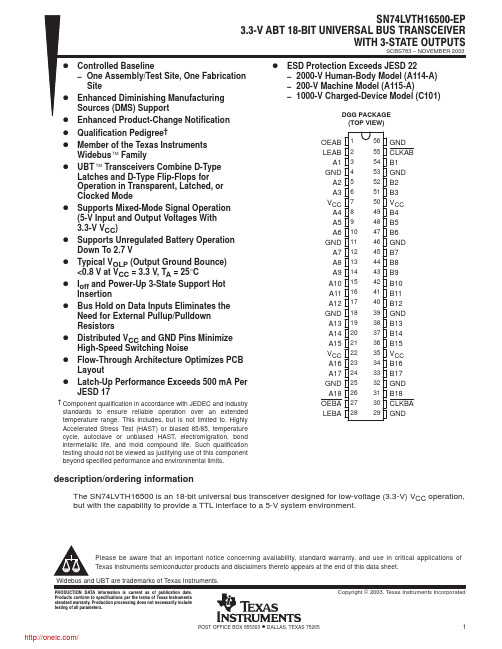
− One Assembly/Test Site, One Fabrication Site Enhanced Diminishing Manufacturing Sources (DMS) Support Enhanced Product-Change Notification Qualification Pedigree† Member of the Texas Instruments Widebus Family UBT Transceivers Combine D-Type Latches and D-Type Flip-Flops for Operation in Transparent, Latched, or Clocked Mode Supports Mixed-Mode Signal Operation (5-V Input and Output Voltages With 3.3-V VCC) Supports Unregulated Battery Operation Down To 2.7 V Typical VOLP (Output Ground Bounce) <0.8 V at VCC = 3.3 V, TA = 25°C Ioff and Power-Up 3-State Support Hot Insertion Bus Hold on Data Inputs Eliminates the Need for External Pullup/Pulldown Resistors Distributed VCC and GND Pins Minimize High-Speed Switching Noise Flow-Through Architecture Optimizes PCB Layout Latch-Up Performance Exceeds 500 mA Per JESD 17
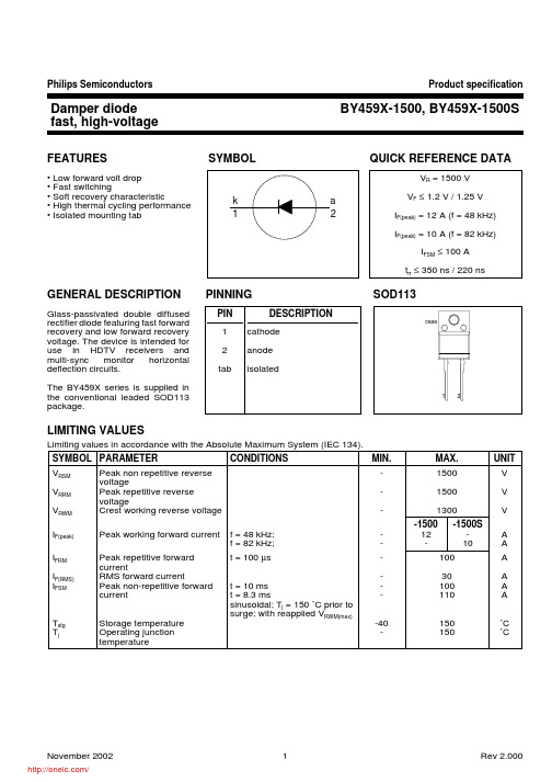
BY459X-1500,127;BY459X-1500S,127;中文规格书,Datasheet资料
T
t
10us 100us 1ms 10ms 100ms 1s 10s
pulse width, tp (s)
BY459F
Fig.7. Transient thermal impedance Zth = f(tp)
Product specification
BY459X-1500, BY459X-1500S
0.25 0.17 2.0 0.70 8.0 11.0 170 200
MAX.
UNIT
1500 1500S
0.35 0.22 µs 3.0 0.95 µC 14.0 19.0 V 250 300 ns
November 2002
2
/
Rev 2.000
Philips Semiconductors
Notes 1. Refer to mounting instructions for F-pack envelopes. 2. Epoxy meets UL94 V0 at 1/8".
November 2002
5
/
Rev 2.000
Philips Semiconductors
trr time
Qs I R
25%
100%
Fig.2. Definition of trr and Qs
VCC
Line output transformer LY
Cf
Cs
deflection transistor
D1
Fig.3. Basic horizontal deflection circuit.
The BY459X series is supplied in the conventional leaded SOD113 package.
- 1、下载文档前请自行甄别文档内容的完整性,平台不提供额外的编辑、内容补充、找答案等附加服务。
- 2、"仅部分预览"的文档,不可在线预览部分如存在完整性等问题,可反馈申请退款(可完整预览的文档不适用该条件!)。
- 3、如文档侵犯您的权益,请联系客服反馈,我们会尽快为您处理(人工客服工作时间:9:00-18:30)。
Please be aware that an important notice concerning availability, standard warranty, and use in critical applications of Texas Instruments semiconductor products and disclaimers thereto appears at the end of this data sheet. Widebus and UBT are trademarks of Texas Instruments.
OEAB LEAB A1 GND A2 A3 VCC A4 A5 A6 GND A7 A8 A9 A10 A11 A12 GND A13 A14 A15 VCC A16 A17 GND A18 OEBA LEBA
1 2 3 4 5 6 7 8 9 10 11 12 13 14 15 16 17 18 19 20 21 22 23 24 25 26 27 28
FUNCTION TABLE† INPUTS OEAB L H H H H H LEAB X H H L L L CLKAB X X X ↑ ↑ H A X L H L H X OUTPUT B Z L H L H B0‡ B0§
56 55 54 53 52 51 50 49 48 47 46 45 44 43 42 41 40 39 38 37 36 35 34 33 32 31 30 29
GND CLKAB B1 GND B2 B3 VCC B4 B5 B6 GND B7 B8 B9 B10 B11 B12 GND B13 B14 B15 VCC B16 B17 GND B18 CLKBA GND
DGG PACKAGE (TOP VIEW)
D
D D D D D D
† Component qualification in accordance with JEDEC and industry standards to ensure reliable operation over an extended temperature range. This includes, but is not limited to, Highly Accelerated Stress Test (HAST) or biased 85/85, temperature cycle, autoclave or unbiased HAST, electromigration, bond intermetallic life, and mold compound life. Such qualification testing should not be viewed as justifying use of this component beyond specified performance and environmental limits.
PRODUCTION DATA information is current as of publication date. Products conform to specifications per the terms of Texas Instruments standard warranty. Production processing does not necessarily include testing of all parameters.
D Flow-Through Architecture Optimizes PCB D D
Layout Latch-Up Performance Exceeds 500 mA Per JESD 17 ESD Protection Exceeds JESD 22 − 2000-V Human-Body Model (A114-A) − 200-V Machine Model (A115-A)
description/ordering information
The SN74LVTH16501 is an 18-bit universal bus transceiver designed for low-voltage (3.3-V) VCC operation, but with the capabiห้องสมุดไป่ตู้ity to provide a TTL interface to a 5-V system environment.
Data flow in each direction is controlled by output-enable (OEAB and OEBA), latch-enable (LEAB and LEBA), and clock (CLKAB and CLKBA) inputs. For A-to-B data flow, the device operates in the transparent mode when LEAB is high. When LEAB is low, the A data is latched if CLKAB is held at a high or low logic level. If LEAB is low, the A data is stored in the latch/flip-flop on the low-to-high transition of CLKAB. When OEAB is high, the outputs are active. When OEAB is low, the outputs are in the high-impedance state. Data flow for B to A is similar to that of A to B, but uses OEBA, LEBA, and CLKBA. The output enables are complementary (OEAB is active high and OEBA is active low). Active bus-hold circuitry holds unused or undriven inputs at a valid logic state. Use of pullup or pulldown resistors with the bus-hold circuitry is not recommended. When VCC is between 0 and 1.5 V, the device is in the high-impedance state during power up or power down. However, to ensure the high-impedance state above 1.5 V, OE should be tied to VCC through a pullup resistor and OE should be tied to GND through a pulldown resistor; the minimum value of the resistor is determined by the current-sinking/current-sourcing capability of the driver. This device is fully specified for hot-insertion applications using Ioff and power-up 3-state. The Ioff circuitry disables the outputs, preventing damaging current backflow through the device when it is powered down. The power-up 3-state circuitry places the outputs in the high-impedance state during power up and power down, which prevents driver conflict.
description/ordering information (continued)
ORDERING INFORMATION
TA PACKAGE† ORDERABLE PART NUMBER TOP-SIDE MARKING
−40°C to 85°C TSSOP − DGG Tape and reel CLVTH16501IDGGREP LH16501EP † Package drawings, standard packing quantities, thermal data, symbolization, and PCB design guidelines are available at /sc/package.
Copyright 2003, Texas Instruments Incorporated
POST OFFICE BOX 655303
• DALLAS, TEXAS 75265
1
/
SCBS784 − NOVEMBER 2003
SN74LVTH16501ĆEP 3.3ĆV ABT 18ĆBIT UNIVERSAL BUS TRANSCEIVER WITH 3ĆSTATE OUTPUTS
SN74LVTH16501ĆEP 3.3ĆV ABT 18ĆBIT UNIVERSAL BUS TRANSCEIVER WITH 3ĆSTATE OUTPUTS
SCBS784 − NOVEMBER 2003
D Controlled Baseline D D D D D
− One Assembly/Test Site, One Fabrication Site Enhanced Diminishing Manufacturing Sources (DMS) Support Enhanced Product-Change Notification Qualification Pedigree† Member of the Texas Instruments Widebus Family UBT Transceiver Combines D-Type Latches and D-Type Flip-Flops for Operation in Transparent, Latched, or Clocked Mode State-of-the-Art Advanced BiCMOS Technology (ABT) Design for 3.3-V Operation and Low Static-Power Dissipation Supports Mixed-Mode Signal Operation (5-V Input and Output Voltages With 3.3-V VCC) Supports Unregulated Battery Operation Down To 2.7 V Typical VOLP (Output Ground Bounce) <0.8 V at VCC = 3.3 V, TA = 25°C Ioff and Power-Up 3-State Support Hot Insertion Bus Hold on Data Inputs Eliminates the Need for External Pullup/Pulldown Resistors Distributed VCC and GND Pins Minimize High-Speed Switching Noise