AX3161-V1.0
NBR1200电信级防攻击宽带路由器产品介绍
NBR1200电信级防攻击宽带路由器产品介绍V2.0福建星网锐捷网络有限公司版权所有侵权必究目录1 产品图片 (1)2 产品概述 (2)3 产品特性 (3)4 技术参数 (7)5 典型应用 (9)6 订购信息 (10)1 产品图片图1-1NBR1200电信级防攻击宽带路由器2 产品概述RG-NBR1200是锐捷网络公司推出的电信级防攻击宽带路由器。
它主要定位于以太网/光纤/ADSL接入的普教中小学、政府、企业机构、网吧、酒店等网络环境。
RG-NBR1200采用RISC架构高性能通讯专用网络处理器。
固化带有2个百兆以太网WAN口,1个独立的光模块扩展插槽,插上模块就提供了3个WAN口,4个百兆以太网LAN口,一个Console配置口。
RG-NBR1200拥有先进的硬件架构,出色的小包转发能力。
内置高性能防火墙,具备防病毒、防攻击能力。
丰富的内网安全特性和智能的带宽管理功能。
人性化的WEB管理和监控界面。
NBR1200的最大带机数为250台。
3 产品特性高速稳定的硬件架构●采用PowerPC RISC高性能通讯专用网络处理器,内嵌锐捷网络自主研发的RGNOS网络操作平台,提供电信级产品的高性能和高稳定性。
●支持硬件端口镜像功能,不影响网络性能,兼容常见信息监控过滤系统,并且监控口在提供监控功能的同时,还可以继续使用,不会影响任何功能。
●内置电信级宽频开关电源,具有防雷、防过压、防浪涌设计,适应电压不稳定场合。
灵活的内外网应用●最多3个百兆WAN口,4个百兆LAN口,所有接口可自动识别网线和交叉线。
●支持VRRP热备份协议和基于Ping/DNS的线路检测,实现多台设备、多条宽带线路的负载均衡和线路备份。
●支持基于目的地址或源地址的负载均衡和强大精细化的策略路由。
●支持电信网通自动选路功能,实现“电信数据自动走电信线路,网通数据自动走网通线路”。
支持南方、北方选路策略,实用效果更好。
●支持采用NAT或公网模式(路由模式)上网。
EMW3165 V1.1中文数据手册

3.1.
3.2. 3Biblioteka 3.工作环境 ........................................................................................................................................................................... 5
EMW3165
Data Sheet
版本:1.1 日期:2015-07-05 嵌入式 Wi-Fi 模块 编号: DS0007C
特性 包含一个 Cortex-M4 微控制器和一个 IEEE 802.11 b/g/n 射频芯片 100MHz 的 Cortex-M4 内核 2M 字节的片外 SPI flash 和 512K 字节的片 内 flash 128K 字节的 RAM
硬件框图
应用 智能 LED 智能家居/ 家电 医疗保健 1
版权声明 未经许可,禁止使用或复制本手册中全部或任何一部 分内容, 这尤其适用于商标、 机型命名、 零件号和图。
目 1. 2.
录
功能简介 ........................................................................................................................................................................................ 1 模块接口 ........................................................................................................................................................................................ 2
Orbi WiFi 六合一路由器系列安装指南说明书
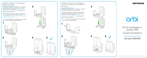
Kit di montaggio aparete Orbi Guida introduttivaModello RBKWMContenuto della confezionePreparazione del supporto di montaggio a pareteCoperchio del montaggio a pareteNota:la staffa e il coperchio sono prefissati.BaseViti (2)Ancoraggi a parete (2)Installare il supporto di montaggio aparete senza la baseUtilizzare questo metodo per installare i modelli Orbi con fori di montaggio sulla parte inferiore.Nota: queste istruzioni riguardano il sistema WiFiSupporto e CommunityVisita /support per trovare le risposte alle tue domande e accedere agli ultimi download. Puoi cercare anche utili consigli nella nostra Community NETGEAR, visitando la pagina .© NETGEAR, Inc. NETGEAR e il logo NETGEAR sono marchi di NETGEAR, Inc. Qualsiasi marchio non‑NETGEAR è utilizzato solo come riferimento.NETGEAR INTERNATIONAL LTD Floor 1, Building 3,University Technology Centre Curraheen Road, Cork, T12EF21, IrlandaNETGEAR, Inc.piazza Della Repubblica 32, 20124 MilanoIMPORTANTE: è possibile installare il supportodi montaggio a parete solo verticalmente su una parete. Non installare il supporto di montaggio a parete orizzontalmente o sul soffitto.Marzo 2020Per la conformità alle normative vigenti, compresa la Dichiarazione di conformità UE, visitare il sito Web https:///about/regulatory/.Prima di collegare l'alimentazione, consultare il documento relativo alla conformità normativa.Per consultare l'Informativa sulla privacy di NETGEAR, visitare il sito Webhttps:///about/privacy‑policy .Utilizzando questo dispositivo, l'utente accetta i Termini e le condizioni di NETGEAR consultabili all'indirizzohttps:///about/terms‑and‑conditions . Se l'utente non accetta tali Termini e condizioni, restituire il dispositivo presso il luogo di acquisto entro il termine previsto per la restituzione.Conformità normativa e note legaliPer ulteriori informazioni su questa configurazione, consultare Installare il supporto di montaggio a parete senza la base .Determinare se il supporto dimontaggio a parete richiede la baseSe il modello Orbi è dotato di fori di montaggio sulla parte inferiore, è possibile installare il supporto di montaggio a parete senza base.Per ulteriori informazioni su questa configurazione, vedere una delle seguenti sezioni sull'altro lato di questa guida rapida:• Installare il supporto di montaggio a parete con la base•Installare il supporto di montaggio a parete con la base per i prodotti Orbi più piccoliSupporto di montaggio a parete senza baseSupporto di montaggio a parete con la base。
华三路由器软件升级指南

亿佰特WiFi模组选型指南以及WiFi模块应用方案详解
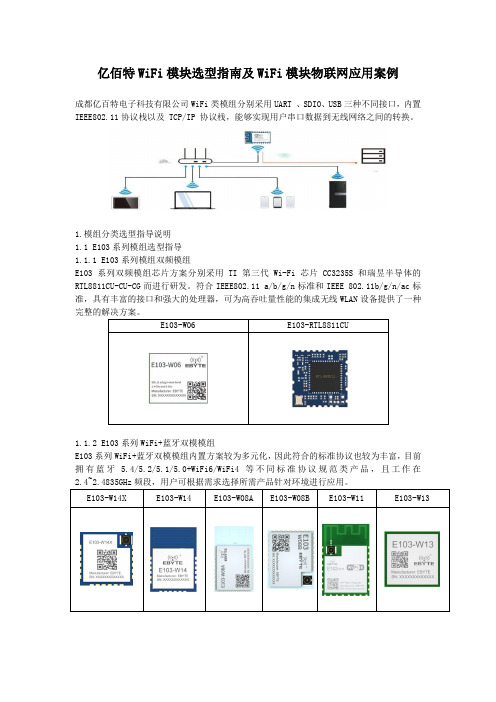
亿佰特WiFi模块选型指南及WiFi模块物联网应用案例成都亿百特电子科技有限公司WiFi类模组分别采用UART 、SDIO、USB三种不同接口,内置IEEE802.11协议栈以及 TCP/IP 协议栈,能够实现用户串口数据到无线网络之间的转换。
1.模组分类选型指导说明1.1 E103系列模组选型指导1.1.1 E103系列模组双频模组E103系列双频模组芯片方案分别采用TI第三代Wi-Fi芯片CC3235S和瑞昱半导体的RTL8811CU-CU-CG而进行研发。
符合IEEE802.11 a/b/g/n标准和IEEE 802.11b/g/n/ac标准,具有丰富的接口和强大的处理器,可为高吞吐量性能的集成无线WLAN设备提供了一种E103-W06 E103-RTL8811CU1.1.2 E103系列WiFi+蓝牙双模模组E103系列WiFi+蓝牙双模模组内置方案较为多元化,因此符合的标准协议也较为丰富,目前拥有蓝牙 5.4/5.2/5.1/5.0+WiFi6/WiFi4等不同标准协议规范类产品,且工作在1.1.3 E103系列超低功耗WiFi模组E103系列低功耗WiFi模组工作在2.4~2.4835GHz 频段,符合IEEE 802.11b/g/n协议标准。
模块集成了透传功能,即拿即用,支持串口 AT 指令集用户通过串口即可使用网络访问的功能,广泛应用于穿戴设备、家庭自动化、家庭安防、个人保健、智能家电、配饰与遥控器、1.1.4 E103系列WiFi路由模组E103系列WiFi路由模组目前拥有两款产品,分别为E103-W20(7688)和 E103-W20(7628)。
该类模块是基于联发科 MT7688AN及 MT7628AN为核心的低成本低功耗的物联网模块。
模块引出了 MT7688AN /MT7628AN的所有接口,支持 OpenWrt 操作系统及自定义开发,具有丰富的接口和强大的处理器,可以广泛的应用于智能设备或云服务应用等,并可以自由进行1.1.5 E103系列通用型模组E103系列通用型模组不仅具有丰富的外设接口,还拥有强大的神经网络运算能力和信号处理能力,成本低,且适用于AloT 领域的多种应用场景,例如唤醒词检测和语音命令识别、E103-RTL8189 E103-W05 E103-W01-IPX E103-W01 E103-W101.1.6 E103系列WiFi mesh模组在 EBYTE 的方案中,我们公司支持WIFI Mesh支持有路由组网和无路由组网的模块为E103-W07,E103-W07是一套建立在Wi-Fi协议之上的网络协议。
精选-无线WiFi-博达企业级智能无线AC控制器宣传彩页

产品概述BDCOM WSC6100系列是上海博达基于多核高性能嵌入式平台打造的高性能、高可靠性的无线AC控制器产品,具有接口全面、功能全面、运行稳定等特点。
支持CAPWAP标准协议,可提供强大的WLAN接入管理与控制能力;支持自动信道管理、无线射频调整、用户负载均衡等功能,提供良好的用户漫游及切换等能力。
WSC6100系列还支持支持认证与计费接口,与博达和业界主流Radius、Portal平台对接组网。
WSC6100-X32B /X64B WSC6100-X128B/X256B主要特性■集中的无线网络管理BDCOM WSC6100系列AC控制器可以独立部署,也可与博达UAC8100和BCP8200云平台配套部署,提供电信级的运营组网能力。
同时支持标准SNMP管理,对用户和AP实施统一管理,大大简化了无线业务网络的部署和维护。
■良好的无缝漫游特性博达WSC6100系列控制器集中转发和本地转发多种组网模式,支持二三层漫游能力。
在集中式组网中,漫游域可不受网络IP规划影响,可让用户在网络规划时,无需关注拓扑,只要考虑无线信号的合理覆盖即可。
该特性不仅方便用户的网络使用,更能降低网络规划和建设的门槛。
■集中的无线网络安全接入博达提供的WLAN无线网络安全支持WEP/WPA/WAP2/802.1x方式,支持无线IPS/IDS,支持二层用户的隔离,支持集中的ACL控制;支持多种认证方式:支持802.1x认证,支持MAC 地址认证,Portal认证,PPPoE认证与WAPI方式认证;支持非法AP检测及后续处理,支持无线攻击防御,支持静态黑白名单,减少非法用户对无线网络冲击。
■全面的QoS保证WSC6100系列支持报文分类和流量控制,支持DSCP流量调度,支持端到端的QoS映射,支持802.11e,支持负荷均衡和接纳控制。
■多样的对接和认证接口WSC6100系列支持Portal2.0和WiFidog双重接口,可与业界主流云平台对接,实现灵活多样的组网和认证、推送能力。
美科星 MERCURY AX1800双频千兆Wi-Fi 6无线路由器 快速安装指南说明书

1 硬件连接2 设置路由器扫一扫下载APP轻松管理路由器关注微信公众号服务支持在身边※ 本指南中产品图片仅为示意,端口数量、类型和位置等请以实际产品为准。
使用连接到路由器网络的设备打开浏览器,访问 ,按照设置向导的指示即可完成路由器设置。
未经深圳市美科星通信技术有限公司明确书面许可,任何单位或个人不得擅自仿制、复制、誊抄或转译本手册部分或全部内容,且不得以营利为目的进行任何方式(电子、影印、录制等)的传播。
声明Copyright © 2020 深圳市美科星通信技术有限公司版权所有 , 保留所有权利。
地址:深圳市南山区高新区高新南四道023号高新工业村R1号B区第三层西段公司网址: 技术支持热线:400-8810-500深圳市美科星通信技术有限公司为深圳市美科星通信技术有限公司注册商标。
本手册提及的所有商标, 由各自所有人拥有。
本手册所提到的产品规格和资讯仅供参考, 如有内容更新, 恕不另行通知。
除非有特殊约定, 本手册仅作为使用指导, 所作陈述均不构成任何形式的担保。
7108502435 REV1.0.1单台路由器的上网配置方法请如图连接路由器。
路由器接通电源后,系统指示灯绿色常亮,等待一段时间后,指示灯闪烁两次,系统启动成功,指示灯变为红色常亮。
设置完成后,请检查系统指示灯状态:配置完成绿色常亮红色常亮路由器等待配置或连接异常工作状态工作说明选择上网方式此处以宽带拨号上网为例访问若无法打开此页面,请参看常见问题解答设置无线名称和无线密码完成设置后重新连接到无线网络,即可正常上网< 1 >< 2 >< 3 >< 4 >连接到路由器的无线信号(无线名称可在产品底部的标贴上找到)·无线路由器·电源适配器·快速安装指南·路由参数记录标贴包装清单:两台路由器距离较远,指示灯橙色常亮,未能发挥强劲信号实力。
TP-Link R系列企业级路由器主要功能配置实例说明书

声明Copyright © 2021 普联技术有限公司版权所有,保留所有权利未经普联技术有限公司明确书面许可,任何单位或个人不得擅自仿制、复制、誊抄或转译本手册部分或全部内容,且不得以营利为目的进行任何方式(电子、影印、录制等)的传播。
为普联技术有限公司注册商标。
本手册提及的所有商标,由各自所有人拥有。
本手册所提到的产品规格和资讯仅供参考,如有内容更新,恕不另行通知。
除非有特殊约定,本手册仅作为使用指导,所作陈述均不构成任何形式的担保。
目录第1章前言 (1)1.1 目标读者 (1)1.2 本书约定 (1)1.3 适用机型 (1)第2章基础联网设置 (3)2.1 企业路由器基本设置指南 (3)2.1.1 应用介绍 (3)2.1.2 需求介绍 (3)2.1.3 设置方法 (3)2.1.4 注意事项 (7)2.2 企业路由器IPv6上网配置指导 (8)2.2.1 应用介绍 (8)2.2.2 需求介绍 (8)2.2.3 设置方法 (8)2.2.4 疑问解答 (15)第3章设备管理 (17)3.1 如何在外网远程管理(控制)路由器? (17)3.1.1 应用介绍 (17)3.1.2 需求介绍 (17)3.1.3 设置方法 (17)3.1.4 注意事项 (20)3.1.5 疑问解答 (21)3.2 如何设置自动重启? (22)3.2.1 应用介绍 (22)3.2.2 需求介绍 (22)3.2.3 设置方法 (22)3.2.4 注意事项 (23)第4章负载均衡 (24)4.1 多WAN口路由器负载均衡的设置指南 (24)4.1.1 应用介绍 (24)4.1.2 需求介绍 (24)4.1.3 工作原理 (24)4.1.4 设置方法 (25)第5章路由转发模块 (27)5.1 策略路由设置指南 (27)5.1.1 应用介绍 (27)5.1.2 需求介绍 (27)5.1.3 设置方法 (28)5.1.4 疑问解答 (31)5.2 ISP选路设置指南 (33)5.2.1 应用介绍 (33)5.2.2 需求介绍 (33)5.2.3 设置方法 (34)5.3 静态路由设置指南 (36)5.3.1 应用介绍 (36)5.3.2 需求介绍 (36)5.3.3 设置方法 (37)5.4 线路备份设置指南 (38)5.4.1 应用介绍 (38)5.4.2 需求介绍 (38)5.4.3 设置方法 (38)5.4.4 注意事项 (40)5.5 虚拟服务器设置指南 (41)5.5.1 应用介绍 (41)5.5.2 需求介绍 (41)5.5.3 设置方法 (42)5.5.4 疑问解答 (43)5.6 NAT-DMZ功能设置指南 (44)5.6.1 应用介绍 (44)5.6.2 需求介绍 (44)5.6.3 设置方法 (45)第6章AP和易展管理 (47)6.1 AP管理设置指南 (47)6.1.1 应用介绍 (47)6.1.2 需求介绍 (47)6.1.3 设置方法 (47)6.2 易展AP设置指南 (53)6.2.1 应用介绍 (53)6.2.2 需求介绍 (53)6.2.3 设置方法 (54)6.2.4 注意事项 (58)第7章行为管控 (59)7.1 连接数限制设置指南 (59)7.1.1 应用介绍 (59)7.1.2 需求介绍 (59)7.1.3 设置方法 (59)7.1.4 疑问解答 (60)7.2 访问控制设置指南 (61)7.2.1 应用介绍 (61)7.2.2 需求介绍 (61)7.2.3 设置方法 (61)7.2.4 疑问解答 (67)7.3 应用限制设置指南 (68)7.3.1 应用介绍 (68)7.3.2 需求介绍 (68)7.3.3 设置方法 (68)7.4 网址过滤设置指南 (71)7.4.1 应用介绍 (71)7.4.2 需求介绍 (71)7.4.3 设置方法 (71)7.4.4 疑问解答 (75)7.5 网页安全设置指南 (76)7.5.1 应用介绍 (76)7.5.2 需求介绍 (76)7.5.3 设置方法 (76)第8章安全防护 (78)8.1 ARP防护设置指南 (78)8.1.1 应用介绍 (78)8.1.2 需求介绍 (78)8.1.3 设置方法 (78)8.1.4 疑问解答 (84)8.2 MAC地址过滤设置指南 (86)8.2.1 应用介绍 (86)8.2.2 需求介绍 (86)8.2.3 设置方法 (86)第9章VPN模块 (88)9.1 IPSec VPN设置指南 (88)9.1.1 应用介绍 (88)9.1.2 需求介绍 (88)9.1.3 设置方法 (89)9.2 L2TP VPN设置指南 (96)9.2.1 应用介绍 (96)9.2.2 需求介绍 (96)9.2.3 设置方法 (97)9.3 PPTP VPN设置指南 (105)9.3.1 应用介绍 (105)9.3.2 需求介绍 (105)9.3.3 设置方法 (106)9.4 L2TP VPN代理上网设置指南 (115)9.4.1 应用介绍 (115)9.4.2 需求介绍 (115)9.4.3 设置方法 (115)9.5 PPTP VPN代理上网设置指南 (120)9.5.1 应用介绍 (120)9.5.2 需求介绍 (120)9.5.3 设置方法 (120)第10章认证管理 (125)10.1 一键上网设置指南 (125)10.1.1 应用介绍 (125)10.1.2 需求介绍 (125)10.1.3 设置方法 (126)10.2 短信认证设置指南 (130)10.2.1 应用介绍 (130)10.2.2 需求介绍 (130)10.2.3 设置方法 (131)10.3 Portal认证设置指南—使用内置WEB服务器和内置认证服务器 (136)10.3.1 应用介绍 (136)10.3.2 需求介绍 (136)10.3.3 设置方法 (137)10.4 Portal认证设置指南—使用内置WEB服务器和外部认证服务器 (141)10.4.1 应用介绍 (141)10.4.2 需求介绍 (141)10.4.3 设置方法 (142)10.5 Portal认证设置指南—使用外置WEB服务器和内置认证服务器 (146)10.5.1 应用介绍 (146)10.5.2 需求介绍 (146)10.5.3 设置方法 (147)10.6 Portal认证设置指南—使用外置WEB服务器和外置认证服务器 (150)10.6.1 应用介绍 (150)10.6.2 需求介绍 (150)10.6.3 设置方法 (151)10.7 免认证策略的使用方法 (154)10.7.1 应用介绍 (154)10.7.2 需求介绍 (154)10.7.3 设置方法 (155)10.8 Portal认证中,外部WEB服务器建立规范 (158)10.8.1 应用介绍 (158)10.8.2 流程规范 (159)第11章工业级特性 (163)11.1 如何使用工业级路由器? (163)11.1.1 产品介绍 (163)11.1.2 需求介绍 (163)11.1.3 设置方法 (164)第12章其它功能 (168)12.1 地址组的设置与管理 (168)12.1.1 应用介绍 (168)12.1.2 需求介绍 (168)12.1.3 设置方法 (168)12.1.4 疑问解答 (170)12.2 带宽控制设置指南 (172)12.2.1 应用介绍 (172)12.2.2 需求介绍 (172)12.2.3 设置方法 (172)12.2.4 疑问解答 (175)12.3 PPPOE服务器应用设置指南 (177)12.3.1 应用介绍 (177)12.3.2 需求介绍 (177)12.3.3 设置方法 (178)12.3.4 疑问解答 (181)12.4 网络唤醒功能使用指南 (183)12.4.1 应用介绍 (183)12.4.2 需求介绍 (183)12.4.3 设置方法 (183)12.5 诊断工具使用指南 (186)12.5.1 应用介绍 (186)12.5.2 需求介绍 (186)12.5.3 设置方法 (187)第1章前言本手册旨在帮助您正确使用R系列企业级路由器。
- 1、下载文档前请自行甄别文档内容的完整性,平台不提供额外的编辑、内容补充、找答案等附加服务。
- 2、"仅部分预览"的文档,不可在线预览部分如存在完整性等问题,可反馈申请退款(可完整预览的文档不适用该条件!)。
- 3、如文档侵犯您的权益,请联系客服反馈,我们会尽快为您处理(人工客服工作时间:9:00-18:30)。
52KHz, 2A PWM Buck DC/DC ConverterGENERAL DESCRIPTIONThe AX3161 series are monolithic IC designed for a step-down DC/DC converter, and own the ability of driving a 2A load without additional transistor. It saves board space. The external shutdown function can be controlled by logic level and then come into standby mode. The internal compensation makes feedback control having good line and load regulation without external design. Regarding protected function, thermal shutdown is to prevent over temperature operating from damage, and current limit is against over current operating of the output switch. If current limit function occurs and V FB is down below 0.5V, the switching frequency will be reduced. An external compensation is easily to system stable; the low ESR output capacitor can be used.The AX3161 series operates at a switching frequency of 52KHz thus allow smaller sized filter components than what would be needed with lower frequency switching regulators. The output version included fixed 5V, 12V, and an adjustable type. The chips are available in standard TO263-5L package.FEATURES-Output voltage: 5V and adjustable output version.-Adjustable version output voltage range, 1.23V to 57V.-52KHz fixed switching frequency.-Voltage mode non-synchronous PWM control.-Thermal-shutdown and current-limit protection.-ON/OFF shutdown control input.-Short Circuit Protect (SCP).-Operating voltage can be up to 60V.-Output load current: 2A.-TO263-5L Pb-Free package.-Low power standby mode.-Built-in switching transistor on chip.Axelite一级代理商: 福贝特国际(香港)有限公司Tel: 0755‐25681756QQ: 94070229 E‐mail: sales@Web: BLOCK DIAGRAMVssSW V CCPIN ASSIGNMENTTO263-5L ( Side View )ABSOLUTE MAXIMUM RATINGSCharacteristics Symbol Rating Unit Maximum Supply Voltage V CC +63 V ON/OFF Pin Input Voltage V EN-0.3 to 35 V Feedback Pin Voltage V FB-0.3 to 35 VOutput Voltage to Ground V OUT -0.8 V Power Dissipation Internally limited PD ( T J-T A ) / θJA W Storage Temperature Range T ST-65 to +150 °C Operating Junction Temperature Range T J-40 to +125 °C Operating Supply Voltage V OP+4.5 to +60 V Thermal Resistance from Junction to case θJC 3.5°C/W Thermal Resistance from Junction to ambient θJA 25°C/WNote 1: θJA is measured with the PCB copper area (need connect to V SS pins) of approximately 3 in2 (Multi-layer).ELECTRICAL CHARACTERISTICS(Unless otherwise specified, T A=25°C, V CC=12V. I LOAD = 0.2A)Characteristics Symbol Conditions Min Typ Max UnitsQuiescent Current I Q V FB=1.5V for Adjustableversion force driver off - 4 8 mAFeedback bias current I FB V FB=1.3V(Adjustable version only) - -10 -50 nAShutdown supply Current I SD EN pin=5VV CC=60V - 100 200 uAOscillator frequency F OSC 405265KHz(Adjustable) When V FB<0.5V - 15 - KHzOscillator frequency of shortcircuit protect F SCP(Fixed)When < VOUT *40% -15-KHzMax. Duty Cycle (ON) V FB=0V force driver on - 100 -Min. Duty Cycle (OFF) DC VFB=1.5V for Adjustableversion force driver off - 0 -%Current limit I CL Pear current, No outside circuitV FB=0V force driver on 2.3 - - A Load Regulation( V△OUT/V OUT ) V△OUT I OUT = 0.2 to 2A - 0.6 1.2 %Saturation voltage V SA T I OUT=2A, No outside circuitV FB=0V force driver on - 1.2 1.4 V SW Pin=0V - - -200 uASW pin leakagecurrentSW Pin=-0.8V I SW LNo outside circuitV FB=1.5V for Adjustableversion force driver offV CC=60V force driver off - -5 - mA V IL Low (regulator ON) - 0.6EN pin logic input thresholdvoltageV IH High (regulator OFF) 2.0 1.3-VEN pin logic input current I H V EN=2.5V (OFF) - -0.1 -10 uA EN pin input current I L V EN=0.5V (ON) - -0.01 -1 uA Thermal shutdown Temp T SD- 150 - °CELECTRICAL CHARACTERISTICS (CONTINUED) APPLICATION CIRCUIT(1) Fixed Output Voltage Versions(2) Adjustable Output Voltage Version with Delayed StartupV OUT = V FB ×(1 +R2R1), V FB = 1.23V, R2 = 0.47K ~ 3K Table 1 Resistor select for output voltage settingV OUT R2 R1 3.3V 1.5K 2.5K 5V 1.5K 4.7K 12V 1.5K 13KVersion Characteristics Symbol ConditionsMin Typ Max UnitsOutput Feedback voltageV FB I LOAD =0.2A V OUT programmed for 3.3V 1.193 1.23 1.267VAX3161-ADJ EfficiencyηV CC = 12V, I LOAD =2A - 79 - %Output voltage V OUT I LOAD =0.2A 4.85 5.00 5.15 V AX3161-5.0VEfficiencyη V CC = 12V, I LOAD =2A - 83 - %L1 recommend value (I OUT=2A,)V OUT 3.3V 5V 12V =12V 100uH 120uH NA V IN=24V 120uH 150uH 200uH V IN=32~48V 120uH 150uH 300uH V INFUNCTION DESCRIPTIONPin FunctionsV CCThis is the positive input supply for the IC switching regulator. A suitable input bypass capacitor must be presented at this pin to minimize voltage transients and to supply the switching currents needed by the regulator.V SSCircuit ground.SWInternal switch. The voltage at this pin switches between (+V CC – V SAT) and approximately – 0.5V, with a duty cycle of approximately V OUT / V CC. To minimize coupling to sensitive circuitry, the PC board copper area connected to this pin should be minimized.FeedbackSenses the regulated output vo l tage to complete the feedback loop.ENAllows the switching regulator circuit to be shutdown using logic level signals thus dropping the total input supply current to approximately 100uA. Pulling this pin below a threshold voltage of approximately 1.3V turns the regulator on, and pulling this pin above1.3V (up to a maximum of V CC) shuts the regulator down. If this shutdown feature is notneeded, the EN pin can be wired to the ground pin.Output Capacitor SelectionThe output capacitor is required to filter the output and provide regulator loop stability. The important capacitor parameters are; the 100 KHz Equivalent Series Resistance (ESR), the RMS ripples current rating, voltage rating, and capacitance value. For the output capacitor, the ESR value is the most important parameter. The ESR can be calculated from the following formula.ESR I VL RIPPLE×Δ= = 0.4A x 80m Ω= 32mVAn aluminum electrolytic capacitor's ESR value is related to the capacitance and its voltage rating. In most case, higher voltage electrolytic capacitors have lower ESR values. Most of the time, capacitors with much higher voltage ratings may be needed to provide the low ESR values required for low output ripple voltage. It is recommended to replace this low ESR capacitor by using a 470µF low ESR values < 80m Ω.Thermal ConsiderationsThe data for these curves was taken with the AX3161 operating as a buck-switching regulator in an ambient temperature of 25°C (still air). These temperature increments are all approximate and are affected by many factors. Higher ambient temperatures require more heat sinker.For the best thermal performance, wide copper traces and generous amounts of printed circuit board copper (need connect to the V SS pins) should be used in the board layout, (One exception is the SW(switch) pin, which should not have large areas of copper.) Large areas of copper provide the best transfer of heat (lower thermal resistance) to the surrounding air, and moving air lowers the thermal resistance even further.Package thermal resistance and junction temperature increments are all approximate. The increments are affected by a lot of factors. Some of these factors include board size, shape, thickness, position, location, and even board temperature. Other factors are, trace width, total printed circuit copper area, copper thickness, single or double-sided, multi-layer board and the amount of solder on the board.The effectiveness of the PC board to dissipate heat also depends on the size, quantity and spacing of other components on the board, as well as whether the surrounding air is still or moving. Furthermore, some of these components such as the catch diode will add heat to the PC board and the heat can vary as the input voltage changes. For the inductor, depending on the physical size, type of core material and the DC resistance, it could either act as a heat sink taking heat away from the board, or it could add heat to the board.TYPICAL CHARACTERISTICSPower on test wave(V IN =12V, V OUT =3.3V, I OUT =2A ) EN on test wave(V IN =12V, V OUT =5V, I OUT=2A )Load Transient Response (V IN =12V, V OUT =3.3V, I OUT =0.2~2A)Efficiency (V OUT =3.3V)Efficiency (V OUT =5.0V)PACKAGE OUTLINESCLand Pattern Recommendation(Unit: mm)Dimensions in Millimeters Dimensions in Inches SymbolMin. Nom. Max. Min. Nom. Max.A 4.06 4.45 4.83 0.16 0.175 0.19 b 0.51 0.76 0.99 0.02 0.03 0.039 C 0.38 0.56 0.74 0.015 0.022 0.029 C2 1.14 1.4 1.65 0.045 0.055 0.065 D 8.38 9.02 9.65 0.33 0.355 0.38 E 9,65 10.2 10.7 0.38 0.4 0.42 e 1.70 BSC 0.067 BSC L 14.6 15.2 15.9 0.575 0.6 0.625 L1 1.78 2.29 2.79 0.07 0.09 0.11 L2 - - 1.68 - - 0.066 Mold flash shall not exceed 0.005inch per side JEDEC outline: TO-263 BA。