09.第九章 热电阻120V测试选件说明书-新版
欧洲共同体标准电压接地电阻测量仪说明书
一、安全提示本说明书包括确保仪器安全使用必须遵守的注意事项和安全规则,因此使用前请务必认真阅读。
在使用本仪器之前,请阅读并理解本说明书所包括的内容。
本说明书要妥善保管,以便随时为测试作参考。
使用本仪器必须严格按照本说明书中描述测试步骤进行。
请务必详细了解本说明书中有关安全方面的内容。
一定要严格遵守相关安全规则,否则可能导致伤害事故或仪器损坏。
安全符号的操作。
请勿在有易燃易爆的环境下测试,否则可能会产生火花引起爆炸。
当本仪器潮湿或使用者的手潮湿的时候请勿做接线动作。
请勿施加超过本仪器的容许界限或测试范围的电量。
当您正在测试时请不要打开电池盖。
请一定不要在出现任何不正常情况的时候进行测试。
如:胶壳破裂,测试线断裂、脱皮外露等。
请用户不要随意拆装本仪器,若需维修请与本公司售后服务部或代理处联系。
当仪器表面湿滑,请不要更换电池或打开电池门,需先用干布擦干后再进行。
若需更换电池或打开电池门,请在关机后进行。
测试前请确认测试线的连接插头都已紧密的插入相应端口内。
当仪器在很长时间不使用时,请把电池取出并放置好。
不要把本仪器暴露在极端温度和潮湿等恶劣环境中。
请用湿布或中性清洁剂去清洁本仪器,不要用磨剂或溶剂。
当本仪器潮湿时,请确定使其干燥后储存。
本仪器中图形标志有以下几种,使用时请注意其内容:表示危险、警告、注意标志 表示有双重绝缘或强化绝缘保护表示交流(AC) 接地符合欧洲共同体(European Union)标准二、特性本仪器采用智能微控制器芯片控制,具有高精度和高可靠性;可用于测量各种电力设施配线,电气设备,防雷设备等接地装置的接地电阻值,还可以进行接地电压测量。
(注:本仪器不适合在室外恶劣环境条件下使用,如下雨、雷电等)2.1 具有背光和电池检测功能。
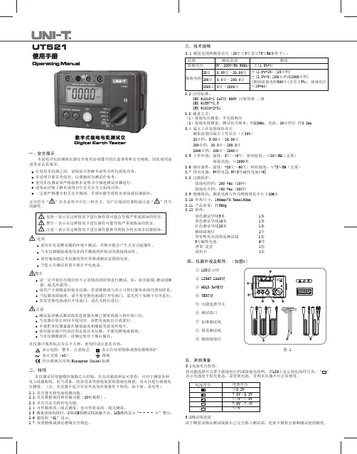
三、技术规格3.1 测量范围和测量误差(20℃±5℃及≤75%RH条件下):范围 测量范围 精度接地电压0V~200V(50/60Hz) ±(1.0%+4)±(2.0%+10) (20Ω档)±(2.0%+3)(200Ω档或2000Ω档)(辅助接地电阻500Ω(误差±5%);接地电压≤10Vac)20Ω 0.00Ω~20.00Ω200Ω0.0Ω~200.0Ω2000Ω0Ω~2000Ω接地电阻3.2 应用标准:IEC 61010-1 CATⅢ 600V 污染等级 二级IEC 61557-1,5IEC 61010-2-313.3 测量方式:(1)接地电压测量:平均值响应(2)接地电阻测量:测试信号频率:约820Hz,电流:20Ω档位 约3.2mA3.4 最大工作范围保持误差测量范围内最大工作误差(±30%)20Ω档:5.00Ω~20.00Ω200Ω档:20.0Ω~200.0Ω2000Ω档:200Ω~2000Ω3.5 工作环境:温度:5℃~40℃;相对湿度:≤80%RH(无雾)海拔高度:≤2000米3.6 储存条件:温度:-20℃~60℃;相对湿度:≤75%RH(无雾)3.7 供电电源:9V供电[1.5V(5号碱性电池)*6]3.8 过载保护:接地电阻档:200 Vac (10秒)接地电压档:400 Vac (30秒)3.9 绝缘阻抗:测量电路与外壳绝缘阻抗不小于20MΩ3.10 外形尺寸:160mmx70.5mmx100mm3.11 产品重量:约560g3.12 附件:绿色测试导线5米 1条黄色测试导线10米 1条红色测试导线20米 1条辅助接地钉 2个带有鳄鱼夹的简易测试线 1套5号碱性电池 6节背带/皮套 1套说明书 1张四、仪器外观及配件:(如图1)图 1① LCD显示屏② LIGHT/LOAD键③ HOLD/SAVE键④ TEST键⑤ 功能选择开关⑥ 测试端口⑦ 标准测试线⑧ 简易测试线⑨ 辅助接地钉2.2 具有数据保持和存储功能(20组数据)。
热电偶和热电阻手册
热电偶和热电阻技术手册作者:天长市金德仪表有限公司网址:/热电偶测量温度时要求其冷端(测量端为热端,通过引线与测量电路连接的端称为冷端)的温度保持不变,其热电势大小才与测量温度呈一定的比例关系。
若测量时,冷端的(环境)温度变化,将影响严重测量的准确性。
在冷端采取一定措施补偿由于冷端温度变化造成的影响称为热电偶的冷端补偿。
热电偶的冷端补偿通常采用在冷端串联一个由热电阻构成的电桥。
电桥的三个桥臂为标准电阻,另外有一个桥臂由(铜)热电阻构成。
当冷端温度变化(比如升高),热电偶产生的热电势也将变化(减小),而此时串联电桥中的热电阻阻值也将变化并使电桥两端的电压也发生变化(升高)。
如果参数选择得好且接线正确,电桥产生的电压正好与热电势随温度变化而变化的量相等,整个热电偶测量回路的总输出电压(电势)正好真实反映了所测量的温度值。
这就是热电偶的冷端补偿原理。
热电阻热电阻是中低温区最常用的一种温度检测器。
它的主要特点是测量精度高,性能稳定。
其中铂热是阻的测量精确度是最高的,它不仅广泛应用于工业测温,而且被制成标准的基准仪。
1、热电阻测温原理及材料热电阻测温是基于金属导体的电阻值随温度的增加而增加这一特性来进行温度测量的。
热电阻大都由纯金属材料制成,目前应用最多的是铂和铜,此外,现在已开始采用镍、锰和锗等材料制造热电阻。
2、热电阻的类型1)普通型热电阻从热电阻的测温原理可知,被测温度的变化是直接通过热电阻阻值的变化来测量的,因此,热电阻体的引出线等各种导线电阻的变化会给温度测量带来影响。
2)恺装热电阻恺装热电阻是由感温元件(电阻体)、引线、绝缘材料、不锈钢套管组合而成的坚实体,它的外径一般为(p2--cp8mm,最小可达cpmm。
与普通型热电阻相比,它有下列优点:①体积小,内部无空气隙,热惯性上,测量滞后小;②机械性能好、耐振,抗冲击;③能弯曲,便于安装④使用寿命长。
3)端面热电阻端面热电阻感温元件由特殊处理的电阻丝材绕制,紧贴在温度计端面。
久茂自动化(大连)有限公司 室内、室外、通道温度测量热电阻说明书
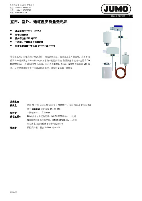
室内、室外、通道温度测量热电阻⏹测温范围-50~+90℃(200℃)⏹用于空调行业⏹防护等级从IP20到IP65⏹二线制、三线制或四线制连接⏹可提供变送器一体化型(4~20mA或0~10V)该电阻温度计主要应用于空调系统,用来测量室温、通风孔及室外的温度。
采用不同的塑料外壳以满足各种特殊应用所要求的不同防护等级。
传感器通常使用一支符合DIN EN 60751 B级二线制的Pt100热电阻,也可提供Pt500、Pt1000、Ni1000型和各种NTC版本。
从接线盒开始可进行三线或四线连接,可提供变送器一体化型。
技术数据接线盒塑料PC支架(材料PP对应型号902520/11),防护等级从IP20到IP65 型号902524/25防护等级IP54和IP65保护管不锈钢1.4571,直径6mm热电阻插芯Pt100热电阻温度传感器,DIN EN 60751 B级,二线制Pt1000热电阻温度传感器,DIN EN 60751 B级,二线制更多热电阻温度传感器请参考选型说明变送器模拟变送器,输出4~20mA或0~10V变送器1所指数据为量程满度20mA2使用较高数据认证/认证标准接线图标准版本变送器用于基本型号902520/10变送器适用于基本型号902520/2x和902524/3x供电单元接线示例,4~20mA和0~10V外形尺寸基本型号 902520/10基本型号 902520/11基本型号 902520/15基本型号 902520/21基本型号 902520/22基本型号902520/23基本型号 902520/24基本型号 902524/25基本型号 902524/31基本型号 902524/32选型说明:室内、室外、通道温度测量热电阻(1)基本型号(1)(2)(3)(4)(5)选型代码- - / (1)选型举例902520/10 - 572 - 1001 - 1 / 0001请逐一列出附加代码,代码顺序由小到大,用逗号隔开2请指明测量范围选型说明:室内、室外、通道温度测量热电阻(1)基本型号×658(1)(2)(3)(4)(5)选型代码- - /选型举例902520/21 - 573 - 1003 - 1 / 000选型说明:室内、室外、通道温度测量热电阻(1)基本型号(1)(2)(3)(4)(5)(6)(7)(8)选型代码- - - - - - / (1)选型举例902524/25 - 380 - 1003 - 1 - 6 - 100 - 000 / 0001请逐一列出附加代码,代码顺序由小到大,用逗号隔开2工艺连接可在“工艺连接附件”部分找到选型说明:室内、室外、通道温度测量热电阻(1)基本型号(1)(2)(3)(4)(5)(6)(7)(8)- - - - - / (1)902524/31 - 380 - 1003 - 1 - 6 - 100 - 000 / 0001请逐一列出附加代码,代码顺序由小到大,用逗号隔开2请指明测量范围过程连接附件。
热电阻操作说明书

热电阻操作说明书1. 概述热电阻是一种用于测量温度的传感器。
它利用材料的温度变化引起的电阻变化来实现温度的测量。
本操作说明书旨在介绍如何正确操作热电阻,以确保准确的温度测量结果。
2. 安装2.1 选择合适的位置在安装热电阻之前,应选择一个适合测量温度的位置。
避免将热电阻放置在易受外部干扰的区域,如直接阳光照射、风口、背后有热源等地方。
2.2 连接电路将热电阻与测量设备相连。
确保电缆连接牢固,无松动或破损。
正确连接热电阻的导线极性,避免引起测量误差。
3. 使用3.1 预热在进行温度测量之前,应充分预热热电阻。
预热时间取决于热电阻的特性,具体可参考产品手册。
预热的目的是确保热电阻的温度与被测温度保持一致,以获得准确的测量结果。
3.2 温度测量将热电阻置于待测物体或环境中,确保它与物体充分接触。
等待一段时间,直到热电阻的温度稳定。
然后,读取温度值,并记录下来。
重复此过程,以获取准确的平均温度值。
4. 维护与保养4.1 清洁定期清洁热电阻,以确保准确的测量结果。
使用软布或刷子轻轻擦拭热电阻的表面,避免使用化学物质或腐蚀剂。
4.2 校准定期校准热电阻,以保证其测量精度。
可以使用专业的校准设备或将其送至认可的机构进行校准。
5. 注意事项- 避免将热电阻暴露在高温、高湿度或腐蚀性环境中,以防止热电阻受损。
- 在测量高温对象时,注意防止热电阻过热,以免影响其寿命和测量准确性。
- 使用过程中如发现热电阻损坏或故障,应立即停止使用并寻求专业维修。
6. 常见问题解答6.1 为什么热电阻的温度测量不准确?可能的原因包括未正确连接电路、热电阻损坏或老化、预热不充分等。
请仔细检查以上因素,并根据需要进行处理或更换热电阻。
6.2 如何延长热电阻的使用寿命?避免将热电阻长时间暴露在高温、高湿度或腐蚀性环境中。
定期清洁和校准热电阻,可以有效延长其使用寿命。
以上是热电阻操作说明书,希望能帮助您正确使用该设备,并获得准确的温度测量结果。
电子热电阻模块应用手册说明书
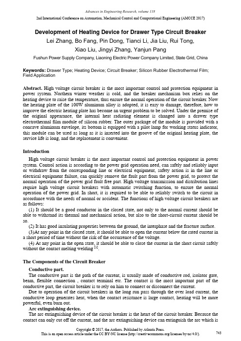
2nd International Conference on Automation, Mechanical Control and Computational Engineering (AMCCE 2017)Development of Heating Device for Drawer Type Circuit Breaker Lei Zhang, Bo Fang, Pin Dong, Tianci Li, Jia Liu, Rui Tong,Xiao Liu, Jingyi Zhang, Yanjun PangFushun Power Supply Company, Liaoning Electric Power Company Limited, State Grid, China Keywords:Drawer Type; Heating Device; Circuit Breaker; Silicon Rubber Electrothermal Film; Field ApplicationAbstract. High voltage circuit breaker is the most important control and protection equipment in power system. Northern winter weather is cold, and the breaker mechanism box relies on the heating device to raise the temperature, thus ensure the normal operation of the circuit breaker. Now the heating plate of the 100W aluminum alloy is adopted, it is easy to damage, therefore, how to improve the electric heating plate has become an urgent problem to be solved. Under the premise of the original appearance, the internal heat radiating element is changed into a drawer type electrothermal film module of silicon rubber. The outer package of the module is provided with a concave aluminum envelope, its bottom is equipped with a pilot lamp for working status indicator, this module can be used as long as it is inserted into the groove of the original heating plate, the service life is long, and the replacement is convenient.IntroductionHigh voltage circuit breaker is the most important control and protection equipment in power system. Control action is according to the power grid operation need, can safely and reliably input or withdraw from the corresponding line or electrical equipment, safety action is in the line or electrical equipment failure, can quickly remove the fault part from the power grid, to protect the normal operation of the power grid fault free part. High voltage transmission and distribution lines require high voltage circuit breakers with automatic switching function, to ensure the normal operation of the power grid. In short, it is required to be able to reliably switch to the circuit in accordance with the needs of normal or accident. The functions of high voltage circuit breakers are as follows:(1) It should be a good conductor in the closed state, not only to the normal current should be able to withstand its thermal and mechanical action, but also to the short-circuit current should be so.(2) It has good insulating properties between the ground, the interphase and the fracture surface.(3)At any point in the closed state, it should be able to open the current below the rated current ina short period of time without the risk of the occurrence of the voltage.(4) At any point in the open state, it should be able to close the current in the short circuit safely without the contact melting welding [1].The Components of the Circuit BreakerConductive part.The conductive part is the path of the current, is usually made of conductive rod, isolator gate, beam, flexible connection , contact terminal etc. The contact is the most important part of the conductive part, the circuit breaker is to rely on him to connect or disconnect the current.Due to operation of the circuit breakers in the long run pass through the over load current, the conductive loop generates heat, when the contact resistance is large contact, heating will be more powerful, even burn out.Arc extinguishing device.The arc extinguishing device of the circuit breaker is the heart of the circuit breaker. Because the contact can only cut off the current, and the arc extinguishing device can extinguish the arc which isgenerated by the contact in the off current. Therefore, its good and bad determines the breaking capacity of circuit breakers to a great extent.Insulation system.The following three aspects must be guaranteed in the circuit breaker.(1) The insulation between the charged part and the ground part, mainly the porcelain bushing, the lifting rod, etc.(2) When the circuit breaker is in the open position, the insulation between the fracture surface is usually guaranteed by insulation oil (vacuum or SF6)(3) The insulation of the phase, three-phase oil circuit breaker mainly rely on insulation oil, insulation separator to insulation.Operating mechanism.The operation mechanism is an important part of the circuit breaker, it can ensure that the contact system in a certain way and a certain speed when divide-shut brake, reliable connection and disconnection of the circuit, The operation of mechanical oil is manual, electromagnetic, spring type. Require him to move flexible and reliable. It requires action flexible and reliable[1].Heating device.A heating device is arranged in a circuit breaker mechanism box, it can raise the temperature in the box to ensure the normal operation of the circuit breaker.The Shortage of Heating DeviceNorthern winter weather is cold, the breaker mechanism box needs to rely on the heating device to raise the temperature in the chamber to ensure the normal operation of the circuit breaker. 100W aluminum alloy plate heater is used in all circuit breakers in Fushun area, The type heating plate adopts a resistance wire inside, the 220V voltage is set up on both ends to cause the resistance wire to heat and it increases the temperature in the mechanism box, but the heat could not be distributed which leads to the resistance wire breakage, damage to the heating system.The Design Principle of the Drawer Type Circuit Breaker Heating DeviceAiming at the problems in the existing technology, based on the excellent properties of silicone rubber electric heating module, and through the heating effect comparison,the article provides a drawer type heating device for 66kV and the above breaker mechanism, which solves the problem of the damage of the heating device in the prior art.The design scheme is as follows:Under the premise of the original appearance, the inner heat radiating element is replaced into a drawer type silicon rubber electrothermal film module, This module uses silicone rubber which has high temperature (-60℃to 250℃), high thermal conductivity (thermal conductivity coefficient of 0.83), good insulation performance ,good strength, high temperature resistant fiber reinforced material and soft electric heating membrane element which is composed of nickel chromium alloy resistance wire or circuit with metal foil heating film, the outer package of the module is provided with a concave aluminum envelope, its bottom is equipped with a pilot lamp for working status indicator, drawer type silicon rubber electrothermal module is inserted into the groove of the original heating plate.Fig.1. Cutaway view of the silicon rubber electrothermal moduleFig.2. Internal structure diagram of the silicon rubber electrothermal moduleFig.3. Installation diagram the silicon rubber electrothermal moduleFig.4. Bottom sketch map after installedField ApplicationThe drawer type silicon rubber heating module is installed in the 220kV bus circuit breaker mechanism box of the ShengLi 220kV substation, since the installation in November 30, 2015, the circuit breaker mechanism box is tested and controlled by a thermometer at 20 ℃, and no hysteresis circuit breaker occurred.The drawer type silicon rubber heating module is installed in the 66kV PingLvYi line circuit breaker mechanism box of the HePing 220kV substation, since the installation in November 30, 2015, the circuit breaker mechanism box is tested and controlled by a thermometer at 20 ℃, and no hysteresis circuit breaker occurred.The advantages of the device are as follows: The silicon rubber electrothermal module has excellent physical strength and flexibility, and can make the electric heating element and the heated object in good contact; It can be designed into various shapes; it has light weight, thin thickness, small heat capacity, and can achieve very fast heating rate; The precision metal electrothermal circuit can further improve the surface power density of the silicon rubber heating element, improve the uniformity of the surface heating power, prolong the service life and have a good control performance; Silicone rubber has good weather resistance and aging resistance, as the surface insulation material of electric heating film, it can effectively prevent the product surface crack and enhance the mechanical strength, and greatly extend the service life of the product; Silicon rubber electrothermal module has good resistance to chemical corrosion resistance, used for wet, corrosive gas and other places of relatively poor environment; It is easy to install; the pilot lamp indicates the working status correctly, prevents the accident of scald when the heating plate is checked. ConclusionsThe design and manufacture of the drawer type heating device is simple, the application is also very convenient, and solve practical problems, so it can be applied to the field work. Through the practical work, we can know that our overall design ideas are correct and clear. Drawer type heating device successfully solved the problem that the circuit breaker mechanism box is not easy to replace the internal heating device because of the cold winter in northern, thereby ensuring the normal operation of the circuit breaker mechanism. Moreover, the bottom of this device is equipped with a pilot lamp for working status indicator, this module can be used as long as it is inserted into the groove of the original heating plate, the service life is long, and the replacement is convenient, so it has a wide range of promotional value and application prospects.References[1] Dan Wenpei, Wang Bing, Qi Ling. An Eample of Eectrical Euipment Testing and Fault Treatment. China Water Conservancy and Hydropower Press, 2012.6[2] Chen Huagang. Preventive Test Method and Diagnosis Technology of Electric Power Equipment [M]. Beijing science and Technology Press.2001[3] Yang Guangyuan. Analysis of The cause of Circuit Rresistance of LW24-72.5Type Circuit Breaker in Guangxi Electric Power.2011。
EMERSON 热电阻和热电偶组件 说明书
参考手册00809-0306-2654,修订版 BA2009 年 9 月热电阻和热电偶组件参考手册参考手册00809-0306-2654,修订版 BA2009 年 9 月热电阻和热电偶 电阻温度计和热电偶组件的安装建议注意操作产品前,请阅读本手册。
为了个人和系统安全以及实现最佳产品性能,请务必在安装、使用和维护本产品前透彻地理解手册内容。
有关更多详细信息,请联系当地的罗斯蒙特代表。
参考手册00809-0306-2654,修订版 BA2009 年 9 月热电阻和热电偶/rosemount 目录第 1简介如何使用本手册 . . . . . . . . . . . . . . . . . . . . . . . . . . . . . . . . . . . . . . . . . .1-1安全消息 . . . . . . . . . . . . . . . . . . . . . . . . . . . . . . . . . . . . . . . . . . . . . . .1-1第 2使用电阻温度计测量温度描述和测量原理 . . . . . . . . . . . . . . . . . . . . . . . . . . . . . . . . . . . . . . . . . .2-1结构 . . . . . . . . . . . . . . . . . . . . . . . . . . . . . . . . . . . . . . . . . . . . . . . . . . .2-1连接方法 . . . . . . . . . . . . . . . . . . . . . . . . . . . . . . . . . . . . . . . . . . . . . . .2-3应用领域 . . . . . . . . . . . . . . . . . . . . . . . . . . . . . . . . . . . . . . . . . . . . . . .2-4第 3使用热电偶测量温度描述和测量原理 . . . . . . . . . . . . . . . . . . . . . . . . . . . . . . . . . . . . . . . . . .3-1保护管的安装. . . . . . . . . . . . . . . . . . . . . . . . . . . . . . . . . . . . . . . . . . . .3-3导线和连接件. . . . . . . . . . . . . . . . . . . . . . . . . . . . . . . . . . . . . . . . . . . .3-3应用领域 . . . . . . . . . . . . . . . . . . . . . . . . . . . . . . . . . . . . . . . . . . . . . . .3-3第 4外壳组件规则和说明. . . . . . . . . . . . . . . . . . . . . . . . . . . . . . . . . . . . . . . . . . . . . .4-1应力 . . . . . . . . . . . . . . . . . . . . . . . . . . . . . . . . . . . . . . . . . . . . . . . .4-1扭矩 . . . . . . . . . . . . . . . . . . . . . . . . . . . . . . . . . . . . . . . . . . . . . . . .4-1外壳组件. . . . . . . . . . . . . . . . . . . . . . . . . . . . . . . . . . . . . . . . . . . . .4-1陶瓷外壳安装 . . . . . . . . . . . . . . . . . . . . . . . . . . . . . . . . . . . . . . . . .4-2变送器连接 . . . . . . . . . . . . . . . . . . . . . . . . . . . . . . . . . . . . . . . . . . .4-2附录 A基本值的公差限值附录 B热电偶的公差限值参考手册00809-0306-2654,修订版 BA 热电阻和热电偶2009 年 9 月目录-2参考手册00809-0306-2654,修订版 BA2009 年 9 月热电阻和热电偶第1部分简介如何使用本手册. . . . . . . . . . . . . . . . . . . . . . .第 1-1 页安全消息. . . . . . . . . . . . . . . . . . . . . . . . . .第 1-1 页如何使用本手册本手册为使用罗斯蒙特 1075 系列提供安装、组态、故障排除和其他程序的信息。
热电阻调试作业指导书
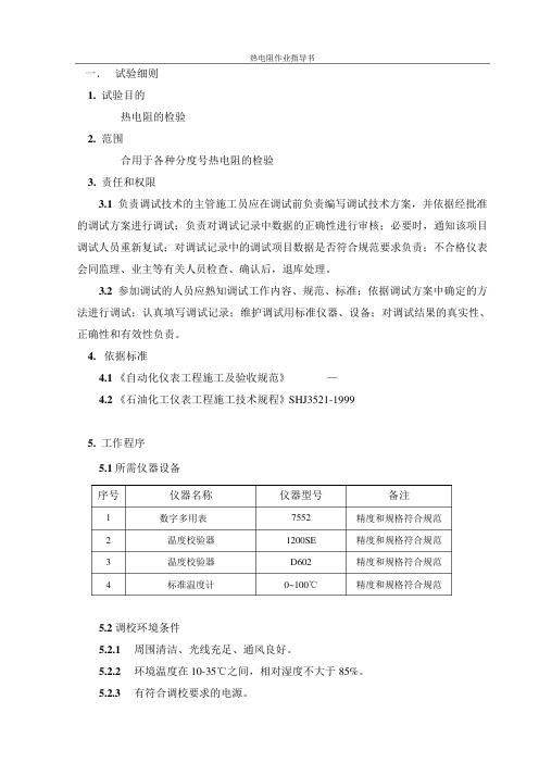
一. 试验细则1. 试验目的热电阻的检验2. 范围合用于各种分度号热电阻的检验3. 责任和权限3.1负责调试技术的主管施工员应在调试前负责编写调试技术方案,并依据经批准的调试方案进行调试;负责对调试记录中数据的正确性进行审核;必要时,通知该项目调试人员重新复试;对调试记录中的调试项目数据是否符合规范要求负责;不合格仪表会同监理、业主等有关人员检查、确认后,退库处理。
3.2参加调试的人员应熟知调试工作内容、规范、标准;依据调试方案中确定的方法进行调试;认真填写调试记录;维护调试用标准仪器、设备;对调试结果的真实性、正确性和有效性负责。
4.依据标准—20024.1《自动化仪表工程施工及验收规范》GB500934.2《石油化工仪表工程施工技术规程》SHJ3521-19995. 工作程序5.1 所需仪器设备序号仪器名称仪器型号备注1 数字多用表7552 精度和规格符合规范2 温度校验器1200SE 精度和规格符合规范3 温度校验器D602 精度和规格符合规范4 标准温度计0~100℃精度和规格符合规范5.2 调校环境条件5.2.1周围清洁、光线充足、通风良好。
5.2.2 环境温度在10-35℃之间,相对湿度不大于85%。
5.2.3有符合调校要求的电源。
5.2.4避开振动大、灰尘多、噪声大和有强磁场干扰的地方。
5.3调校前的准备工作5.3.1 制定调校技术方案,进行技术交底。
5.3.2熟悉仪表说明书、仪表规格书;掌握仪表性能及操作要求。
5.3.3标准仪器要具备有效的检定合格证;基本误差的绝对值不应超过被校仪表基本误差绝对值的1/3。
5.4 调校方法5.4.1外观检查5.4.1.1铭牌及设备的型号、规格、材质、测量范围、技术条件应符合设计要求。
5.4.1.2无变形、损伤、油漆脱落、零件丢失等缺陷;外形主要尺寸、连接尺寸符合设计要求5.4.1.3端子、接头固定件等应完整;附件齐全。
合格证及检定证书齐备。
5.4.2热电阻的导通及绝缘性能的检验用万用表检查正、负极两端的导通。
热电阻测温仪使用说明书
热电阻测温仪使用说明书欢迎使用热电阻测温仪!本使用说明书旨在帮助您正确操作和了解热电阻测温仪,以确保您能够准确测量温度并得到可靠的结果。
请按照以下步骤进行操作:1. 介绍与规格热电阻测温仪是一种基于电阻对温度变化的测量原理的仪器。
它由外壳、温度传感器、显示屏、按钮和电源组成。
采用了先进的技术,具有高精度和稳定性。
主要规格:- 测量范围:-50℃至150℃- 精度:±0.5℃- 分辨率:0.1℃- 响应时间:<5秒- 电源:两节AAA电池- 尺寸:150mm x 25mm x 15mm- 重量:50g2. 使用方法步骤一:装载电池打开背部的电池仓盖,按照正确的正负极方向将两节AAA电池放入电池仓,然后将电池仓盖牢固地关闭。
步骤二:测量温度首先,请确保热电阻测温仪的温度传感器头部干净,没有污垢或异物。
然后,将温度传感器头部轻轻插入您需要测量温度的物体或液体中,待仪表稳定后,读取显示屏上的温度数值即可。
步骤三:单位切换按下仪器侧边的“单位”按钮,即可在摄氏度(℃)和华氏度(℉)之间进行切换。
3. 注意事项- 避免将热电阻测温仪浸入液体中,以免损坏仪器。
- 在测量温度前,请确保温度传感器头部干净,以免影响测量结果。
- 避免将热电阻测温仪暴露在极端高温或低温环境中,以免损坏仪器。
- 长时间不使用热电阻测温仪时,请取出电池,以免电池漏液导致仪器损坏。
- 如有需求,可以使用软布轻轻擦拭热电阻测温仪的外壳,但请注意避免使用化学溶剂或腐蚀性液体。
4. 故障排除如果您在使用热电阻测温仪时遇到以下问题,请参考以下解决方法:- 仪器不能开机:请检查电池是否安装正确,并确保电池电量充足。
- 温度显示不准确:请确保温度传感器头部清洁,并避免使用在极端温度环境下。
5. 免责声明本产品仅为测量温度提供参考数据,不作为精密温度测量仪器。
使用本产品时请遵循使用说明,并对数据的准确性负责。
感谢您选购热电阻测温仪。
如有任何疑问或问题,请及时联系我们的客户服务部门,我们将竭诚为您提供支持和帮助!。
- 1、下载文档前请自行甄别文档内容的完整性,平台不提供额外的编辑、内容补充、找答案等附加服务。
- 2、"仅部分预览"的文档,不可在线预览部分如存在完整性等问题,可反馈申请退款(可完整预览的文档不适用该条件!)。
- 3、如文档侵犯您的权益,请联系客服反馈,我们会尽快为您处理(人工客服工作时间:9:00-18:30)。
热电阻测试说明书
1 概略
1.1 VBE功能件,是通过测试主机,作为PN接触面的温度变化(mV),测试器件的
热电阻特性,再与规定值比较及判断,并表示△VF值。
2 规格
2.1 测试范围
2.1.1 所测器件:晶体管、MOS的FET、二极管
2.1.2 Pre-check:B-E间的OPEN, SHORT
2.1.3 测试范围:△VBE / ⊿VDS000.0m~999.9mV[ 精确度: ±(1%
+3mV) ]
2.2 设定范围
2.3 印加可能范围: 最大规格:150W/10ms
Power Curve
1.00
10.00
VC (V)
IE (A)
2.4
测试热电阻必要的设备:(DTS-1000测试机一台)
1 TPU-1150 (Power unit) 120V 电源
2 PCB-004
3 (Control PCB) 控制板 3 HD-1220 热电阻测试站
※ 由于VCC=120V ,标准DTS 的LV1板的进行改造才可以测试。
注意安全:
由于测试的回路含有大容量的电容器,所以在关断DTS 主电源以后请等待5分钟后再连接与拆除相关的电缆,切记!
4 VBE 使用规格:使用△VBE功能件,需要以下的条件
4.1 测试主机:DTS-1000(只限:M11-1000V20A)
4.2 系统软件:需要另外提供
5 系统构成
6 热电阻测试:
所谓半导体的热电阻,是指器件消耗1W电力时,内部元件和封装表面,周围空气之间的温度差。
热电阻=1W热量的是移动,即每秒移动1个焦耳时的温度差(℃/w)
作为资料的表示方法。
(1)θjc(每1W时,内部元件接触部和封装表面之间的热电阻)
(2)θca(每1W时,封装表面和周围空气之间的热电阻)
(3)θja(每1W时,内部元件接触部和周围空气之间的热电阻θjc+θca)
(4)Tj(半导体元件接触部温度,作为资料性能,保证的最高温度为能Tjmax ,可以用下列的关系式来表示。
Tj=(θjc+θca)× P +Ta=(θja )× P +Ta
P:消費電力 Ta:周围空气温度
元件的构成及形状
另外,要直接测试半导体元件的电力损失部分,电极及IC的芯片,是不可能的。
这样,通过和温度上升或正比的PN 连接,测试对温度上升敏感的ICBO 等就能测出温度的上升。
一般用PN 连接顺方向电压[VF]求其温度。
所以,既然知道了半导体PN 连接部的电压变化,就有可能知道温度的上升。
晶体管在B-E之间有PN 连接部,FET在S-D间有寄生的二极管,利用这个,测试内部连接的温度,能知道安全动作领域,(利用PN 连接的方法,是最稳定的方法,其他方法也可以,比如FET 的VGS部分,漏电流、HFE也能知道其温度。
)
DTS热电阻测试选件,用A-K间、B-E间、S-D间来测试。
7 热电阻的测试原理
7.1 首先,在晶体管加上VCB电压,注入IM(测试电流),电力印加前的温度状态的
VFB后电压值VBE1(加小的电力测试以免温度上升)
7.2 一定时间印加IE电流,这时,晶体管在VCE*IE(W)的电力下加热。
7.3 把状态快速回到同(1)一样的IM电流偏置,测试电力印加后的VBE2。
对正常说的VBE1值和印加电力PW=IE*VC后的VBE2就能求出△VBE=VBE1-VBE2,作为测试结果,所表示的值,已经是△VBE值。
一般来说,后来元件的温度变化为2mV/℃,所以知道△VBE÷2mV/℃,加上一定的电力,就能知道晶体管的温度上升了多少。
比如:VBE1值=650→印加电力=VCE×IE=50V×1A=100w(1sec)→VBE2值=450mV的条件,△VBE =650mV-450mV=2000mV,其晶体管,通过印加100W(1sec),△VBE=200Mv,200mV÷2mV=100℃,就能求得B-E连接上升为℃100℃
8 软件的使用:
8.1 使用Juno软件的Editor程序,在原有测试文件中增加热电阻测试项目:
二极管DVF
三极管DVBE
场效应管DVDS
8.2 系统显示相应的测试参数设置窗口,根据提示设定相关的测试参数:
8.3 完成新增加的测试项目设定后,再次保存测试文件即可。