Adding Ribbon Control To Your Application
ADLRAN ATLAS 800PLUS 使用手册说明书

iv
Affidavit Requirements for Connection to Digital Services • An affidavit is required to be given to the telephone company whenever digital terminal equipment
901 Explorer Boulevard P.O. Box 140000
Huntsville, AL 35814-4000 (256) 963-8000
© 2000 ADTRAN, Inc. All Rights Reserved.
Prinns require that in this manual the following information be provided to the customer:
6. This unit contains no user-serviceable parts. 7. The following information may be required when applying to your local telephone company for
leased line facilities.
without encoded analog content and billing protection is used to transmit digital signals containing encoded analog content which are intended for eventual conversion into voiceband analog signals and transmitted on the network. • The affidavit shall affirm that either no encoded analog content or billing information is being transmitted or that the output of the device meets Part 68 encoded analog content or billing protection specifications. • End user/customer will be responsible for filing an affidavit with the local exchange carrier when connecting unprotected customer premise equipment (CPE) to 1.544 Mbps or subrate digital services. • Until such time as subrate digital terminal equipment is registered for voice applications, the affidavit requirement for subrate services is waived.
Windows Vista Parental Controls 用户指南说明书

Learn more about how you can use Windows to simplify your life with Windows Guides
2
W I N D O W S G U I D E Using Parental Controls
Windows Vista Parental Controls (continued)
Ultimate versions for Windows Media Center) n Family Safety for Windows Live OneCare™—available as a free
download
Windows Guides is a library of easy-to-use guides that show you how to get more from your Windows experience. Share these guides with your friends and family.
n Set up Web restrictions
n Set program limits
n Set up which games your children can play
n Set time limits for computer use
Parental Controls, part of the User Accounts and Family Safety Control Panel, centralizes all of the key settings of the Windows Vista Parental Controls. From this one location, you can configure the parental controls for your computer and applications, setting appropriate limits on your children’s game playing, Web browsing, and overall computer use. You can review activity reports that show how your children have been using the computer. Monitoring your children’s computer behavior not only makes it easy for you to keep track of what they are seeing, hearing, and doing, but it also enables you to refine and modify parental controls based on actual feedback. For your children, the Parental Controls icon in the system tray is always visible to let them know that the Parental Controls feature is on.
HP Color LaserJet Enterprise MFP M776用户指南说明书
Legal informationCopyright and License© Copyright 2019 HP Development Company, L.P.Reproduction, adaptation, or translation without prior written permission is prohibited, except as allowedunder the copyright laws.The information contained herein is subject to change without notice.The only warranties for HP products and services are set forth in the express warranty statementsaccompanying such products and services. Nothing herein should be construed as constituting anadditional warranty. HP shall not be liable for technical or editorial errors or omissions contained herein.Edition 1, 10/2019Trademark CreditsAdobe®, Adobe Photoshop®, Acrobat®, and PostScript® are trademarks of Adobe Systems Incorporated.Apple and the Apple logo are trademarks of Apple Inc., registered in the U.S. and other countries.macOS is a trademark of Apple Inc., registered in the U.S. and other countries.AirPrint is a trademark of Apple Inc., registered in the U.S. and other countries.Google™ is a trademark of Google Inc.Microsoft®, Windows®, Windows® XP, and Windows Vista® are U.S. registered trademarks of MicrosoftCorporation.UNIX® is a registered trademark of The Open Group.iiiT able of contents1 Printer overview (1)Warning icons (1)Potential shock hazard (2)Printer views (2)Printer front view (2)Printer back view (4)Interface ports (4)Control-panel view (5)How to use the touchscreen control panel (7)Printer specifications (8)T echnical specifications (8)Supported operating systems (11)Mobile printing solutions (12)Printer dimensions (13)Power consumption, electrical specifications, and acoustic emissions (15)Operating-environment range (15)Printer hardware setup and software installation (16)2 Paper trays (17)Introduction (17)Load paper to Tray 1 (multipurpose tray) (17)Load Tray 1 (multipurpose tray) (18)Tray 1 paper orientation (19)Use alternative letterhead mode (24)Enable Alternative Letterhead Mode by using the printer control-panel menus (24)Load paper to Tray 2 (24)Load Tray 2 (24)Tray 2 paper orientation (26)Use alternative letterhead mode (29)Enable Alternative Letterhead Mode by using the printer control-panel menus (29)Load paper to the 550-sheet paper tray (30)Load paper to the 550-sheet paper tray (30)550-sheet paper tray paper orientation (32)Use alternative letterhead mode (35)Enable Alternative Letterhead Mode by using the printer control-panel menus (35)ivLoad paper to the 2 x 550-sheet paper trays (36)Load paper to the 2 x 550-sheet paper trays (36)2 x 550-sheet paper tray paper orientation (38)Use alternative letterhead mode (41)Enable Alternative Letterhead Mode by using the printer control-panel menus (41)Load paper to the 2,700-sheet high-capacity input paper trays (41)Load paper to the 2,700-sheet high-capacity input paper trays (41)2,700-sheet HCI paper tray paper orientation (43)Use alternative letterhead mode (45)Enable Alternative Letterhead Mode by using the printer control-panel menus (45)Load and print envelopes (46)Print envelopes (46)Envelope orientation (46)Load and print labels (47)Manually feed labels (47)Label orientation (48)3 Supplies, accessories, and parts (49)Order supplies, accessories, and parts (49)Ordering (49)Supplies and accessories (50)Maintenance/long-life consumables (51)Customer self-repair parts (51)Dynamic security (52)Configure the HP toner-cartridge-protection supply settings (53)Introduction (53)Enable or disable the Cartridge Policy feature (53)Use the printer control panel to enable the Cartridge Policy feature (54)Use the printer control panel to disable the Cartridge Policy feature (54)Use the HP Embedded Web Server (EWS) to enable the Cartridge Policy feature (54)Use the HP Embedded Web Server (EWS) to disable the Cartridge Policy feature (55)Troubleshoot Cartridge Policy control panel error messages (55)Enable or disable the Cartridge Protection feature (55)Use the printer control panel to enable the Cartridge Protection feature (56)Use the printer control panel to disable the Cartridge Protection feature (56)Use the HP Embedded Web Server (EWS) to enable the Cartridge Protection feature (56)Use the HP Embedded Web Server (EWS) to disable the Cartridge Protection feature (57)Troubleshoot Cartridge Protection control panel error messages (57)Replace the toner cartridges (58)T oner-cartridge information (58)Remove and replace the cartridges (59)Replace the imaging drums (62)Imaging drum information (62)Remove and replace the imaging drums (63)Replace the toner-collection unit (66)T oner-collection unit information (66)vRemove and replace the toner-collection unit (67)Replace the staple cartridge (M776zs model only) (70)Staple cartridge information (70)Remove and replace the staple cartridge (71)4 Print (73)Print tasks (Windows) (73)How to print (Windows) (73)Automatically print on both sides (Windows) (74)Manually print on both sides (Windows) (74)Print multiple pages per sheet (Windows) (75)Select the paper type (Windows) (75)Additional print tasks (76)Print tasks (macOS) (77)How to print (macOS) (77)Automatically print on both sides (macOS) (77)Manually print on both sides (macOS) (77)Print multiple pages per sheet (macOS) (78)Select the paper type (macOS) (78)Additional print tasks (79)Store print jobs on the printer to print later or print privately (79)Introduction (79)Create a stored job (Windows) (79)Create a stored job (macOS) (80)Print a stored job (81)Delete a stored job (81)Delete a job that is stored on the printer (81)Change the job storage limit (82)Information sent to printer for Job Accounting purposes (82)Mobile printing (82)Introduction (82)Wi-Fi, Wi-Fi Direct Print, NFC, and BLE printing (82)Enable wireless printing (83)Change the Wi-Fi Direct name (83)HP ePrint via email (83)AirPrint (84)Android embedded printing (85)Print from a USB flash drive (85)Enable the USB port for printing (85)Method one: Enable the USB port from the printer control panel (85)Method two: Enable the USB port from the HP Embedded Web Server (network-connectedprinters only) (85)Print USB documents (86)Print using high-speed USB 2.0 port (wired) (86)Method one: Enable the high-speed USB 2.0 port from the printer control panel menus (86)Method two: Enable the high-speed USB 2.0 port from the HP Embedded Web Server (network-connected printers only) (87)vi5 Copy (88)Make a copy (88)Copy on both sides (duplex) (90)Additional copy tasks (92)6 Scan (93)Set up Scan to Email (93)Introduction (93)Before you begin (93)Step one: Access the HP Embedded Web Server (EWS) (94)Step two: Configure the Network Identification settings (95)Step three: Configure the Send to Email feature (96)Method one: Basic configuration using the Email Setup Wizard (96)Method two: Advanced configuration using the Email Setup (100)Step four: Configure the Quick Sets (optional) (104)Step five: Set up Send to Email to use Office 365 Outlook (optional) (105)Introduction (105)Configure the outgoing email server (SMTP) to send an email from an Office 365 Outlookaccount (105)Set up Scan to Network Folder (108)Introduction (108)Before you begin (108)Step one: Access the HP Embedded Web Server (EWS) (108)Step two: Set up Scan to Network Folder (109)Method one: Use the Scan to Network Folder Wizard (109)Method two: Use Scan to Network Folder Setup (110)Step one: Begin the configuration (110)Step two: Configure the Scan to Network Folder settings (111)Step three: Complete the configuration (118)Set up Scan to SharePoint (118)Introduction (118)Before you begin (118)Step one: Access the HP Embedded Web Server (EWS) (118)Step two: Enable Scan to SharePoint and create a Scan to SharePoint Quick Set (119)Scan a file directly to a SharePoint site (121)Quick Set scan settings and options for Scan to SharePoint (122)Set up Scan to USB Drive (123)Introduction (124)Step one: Access the HP Embedded Web Server (EWS) (124)Step two: Enable Scan to USB Drive (124)Step three: Configure the Quick Sets (optional) (125)Default scan settings for Scan to USB Drive setup (126)Default file settings for Save to USB setup (126)Scan to email (127)Introduction (127)Scan to email (127)Scan to job storage (129)viiIntroduction (129)Scan to job storage on the printer (130)Print from job storage on the printer (132)Scan to network folder (132)Introduction (132)Scan to network folder (132)Scan to SharePoint (134)Introduction (134)Scan to SharePoint (134)Scan to USB drive (136)Introduction (136)Scan to USB drive (136)Use HP JetAdvantage business solutions (138)Additional scan tasks (138)7 Fax (140)Set up fax (140)Introduction (140)Set up fax by using the printer control panel (140)Change fax configurations (141)Fax dialing settings (141)General fax send settings (142)Fax receive settings (143)Send a fax (144)Additional fax tasks (146)8 Manage the printer (147)Advanced configuration with the HP Embedded Web Server (EWS) (147)Introduction (147)How to access the HP Embedded Web Server (EWS) (148)HP Embedded Web Server features (149)Information tab (149)General tab (149)Copy/Print tab (150)Scan/Digital Send tab (151)Fax tab (152)Supplies tab (153)Troubleshooting tab (153)Security tab (153)HP Web Services tab (154)Networking tab (154)Other Links list (156)Configure IP network settings (157)Printer sharing disclaimer (157)View or change network settings (157)Rename the printer on a network (157)viiiManually configure IPv4 TCP/IP parameters from the control panel (158)Manually configure IPv6 TCP/IP parameters from the control panel (158)Link speed and duplex settings (159)Printer security features (160)Introduction (160)Security statements (160)Assign an administrator password (160)Use the HP Embedded Web Server (EWS) to set the password (160)Provide user access credentials at the printer control panel (161)IP Security (161)Encryption support: HP High Performance Secure Hard Disks (161)Lock the formatter (161)Energy-conservation settings (161)Set the sleep timer and configure the printer to use 1 watt or less of power (161)Set the sleep schedule (162)Set the idle settings (162)HP Web Jetadmin (163)Software and firmware updates (163)9 Solve problems (164)Customer support (164)Control panel help system (165)Reset factory settings (165)Introduction (165)Method one: Reset factory settings from the printer control panel (165)Method two: Reset factory settings from the HP Embedded Web Server (network-connectedprinters only) (166)A “Cartridge is low” or “Cartridge is very low” message displays on the printer control panel (166)Change the “Very Low” settings (166)Change the “Very Low” settings at the control panel (166)For printers with fax capability (167)Order supplies (167)Printer does not pick up paper or misfeeds (167)Introduction (167)The printer does not pick up paper (167)The printer picks up multiple sheets of paper (171)The document feeder jams, skews, or picks up multiple sheets of paper (174)Clear paper jams (174)Introduction (174)Paper jam locations (174)Auto-navigation for clearing paper jams (175)Experiencing frequent or recurring paper jams? (175)Clear paper jams in the document feeder - 31.13.yz (176)Clear paper jams in Tray 1 (13.A1) (177)Clear paper jams in Tray 2 (13.A2) (182)Clear paper jams in the fuser (13.B9, 13.B2, 13.FF) (188)ixClear paper jams in the duplex area (13.D3) (194)Clear paper jams in the 550-sheet trays (13.A3, 13.A4) (199)Clear paper jams in the 2 x 550 paper trays (13.A4, 13.A5) (206)Clear paper jams in the 2,700-sheet high-capacity input paper trays (13.A3, 13.A4, 13.A5, 13.A7) (213)Resolving color print quality problems (220)Introduction (220)Troubleshoot print quality (221)Update the printer firmware (221)Print from a different software program (221)Check the paper-type setting for the print job (221)Check the paper type setting on the printer (221)Check the paper type setting (Windows) (221)Check the paper type setting (macOS) (222)Check toner-cartridge status (222)Step one: Print the Supplies Status Page (222)Step two: Check supplies status (222)Print a cleaning page (222)Visually inspect the toner cartridge or cartridges (223)Check paper and the printing environment (223)Step one: Use paper that meets HP specifications (223)Step two: Check the environment (223)Step three: Set the individual tray alignment (224)Try a different print driver (224)Troubleshoot color quality (225)Calibrate the printer to align the colors (225)Troubleshoot image defects (225)Improve copy image quality (233)Check the scanner glass for dirt and smudges (233)Calibrate the scanner (234)Check the paper settings (235)Check the paper selection options (235)Check the image-adjustment settings (235)Optimize copy quality for text or pictures (236)Edge-to-edge copying (236)Improve scan image quality (236)Check the scanner glass for dirt and smudges (237)Check the resolution settings (238)Check the color settings (238)Check the image-adjustment settings (239)Optimize scan quality for text or pictures (239)Check the output-quality settings (240)Improve fax image quality (240)Check the scanner glass for dirt and smudges (240)Check the send-fax resolution settings (242)Check the image-adjustment settings (242)Optimize fax quality for text or pictures (242)Check the error-correction setting (243)xSend to a different fax machine (243)Check the sender's fax machine (243)Solve wired network problems (244)Introduction (244)Poor physical connection (244)The computer is unable to communicate with the printer (244)The printer is using incorrect link and duplex settings for the network (245)New software programs might be causing compatibility problems (245)The computer or workstation might be set up incorrectly (245)The printer is disabled, or other network settings are incorrect (245)Solve wireless network problems (245)Introduction (245)Wireless connectivity checklist (245)The printer does not print after the wireless configuration completes (246)The printer does not print, and the computer has a third-party firewall installed (246)The wireless connection does not work after moving the wireless router or printer (247)Cannot connect more computers to the wireless printer (247)The wireless printer loses communication when connected to a VPN (247)The network does not appear in the wireless networks list (247)The wireless network is not functioning (247)Reduce interference on a wireless network (248)Solve fax problems (248)Checklist for solving fax problems (248)What type of phone line are you using? (249)Are you using a surge-protection device? (249)Are you using a phone company voice-messaging service or an answering machine? (249)Does your phone line have a call-waiting feature? (249)Check fax accessory status (249)General fax problems (250)The fax failed to send (250)No fax address book button displays (250)Not able to locate the Fax settings in HP Web Jetadmin (250)The header is appended to the top of the page when the overlay option is enabled (251)A mix of names and numbers is in the recipients box (251)A one-page fax prints as two pages (251)A document stops in the document feeder in the middle of faxing (251)The volume for sounds coming from the fax accessory is too high or too low (251)Index (252)xiPrinter overview1Review the location of features on the printer, the physical and technical specifications of the printer,and where to locate setup information.For video assistance, see /videos/LaserJet.The following information is correct at the time of publication. For current information, see /support/colorljM776MFP.For more information:HP's all-inclusive help for the printer includes the following information:●Install and configure●Learn and use●Solve problems●Download software and firmware updates●Join support forums●Find warranty and regulatory informationWarning iconsUse caution if you see a warning icon on your HP printer, as indicated in the icon definitions.●Caution: Electric shock●Caution: Hot surface●Caution: Keep body parts away from moving partsPrinter overview1●Caution: Sharp edge in close proximity●WarningPotential shock hazardReview this important safety information.●Read and understand these safety statements to avoid an electrical shock hazard.●Always follow basic safety precautions when using this product to reduce risk of injury from fire orelectric shock.●Read and understand all instructions in the user guide.●Observe all warnings and instructions marked on the product.●Use only a grounded electrical outlet when connecting the product to a power source. If you do notknow whether the outlet is grounded, check with a qualified electrician.●Do not touch the contacts on any of the sockets on the product. Replace damaged cordsimmediately.●Unplug this product from wall outlets before cleaning.●Do not install or use this product near water or when you are wet.●Install the product securely on a stable surface.●Install the product in a protected location where no one can step on or trip over the power cord.Printer viewsIdentify certain parts of the printer and the control panel.Printer front viewLocate features on the front of the printer.2Chapter 1 Printer overviewPrinter front view3Printer back viewLocate features on the back of the printer.Interface portsLocate the interface ports on the printer formatter. 4Chapter 1 Printer overviewControl-panel viewThe control panel provides access to the printer features and indicates the current status of the printer.NOTE:Tilt the control panel for easier viewing.The Home screen provides access to the printer features and indicates the current status of the printer.screens.NOTE:The features that appear on the Home screen can vary, depending on the printerconfiguration.Control-panel view5Figure 1-1Control-panel view?i 12:42 PM6Chapter 1 Printer overviewHow to use the touchscreen control panelPerform the following actions to use the printer touchscreen control panel.T ouchT ouch an item on the screen to select that item or open that menu. Also, when scrolling T ouch the Settings icon to open the Settings app.How to use the touchscreen control panel 7SwipeT ouch the screen and then move your finger horizontally to scroll the screen sideways.Swipe until the Settings app displays.Printer specificationsDetermine the specifications for your printer model.IMPORTANT:The following specifications are correct at the time of publication, but they are subject to change. For current information, see /support/colorljM776MFP .T echnical specificationsReview the printer technical specifications.Product numbers for each model ●M776dn - #T3U55A ●Flow M776z - #3WT91A ●Flow M776zs - #T3U56APaper handling specificationsPaper handling features Tray 1 (100-sheet capacity)Included Included Included Tray 2 (550-sheet capacity)IncludedIncludedIncluded8Chapter 1 Printer overview550-sheet paper trayOptional Included Not included NOTE:The M776dn models accept one optional550-sheet tray.Optional Included Included2 x 550-sheet paper tray and standNOTE:The M776dn models accept one optional550-sheet tray that may be installed on top of thestand.Optional Not included Not included2,700-sheet high-capacity input (HCI) paper trayand standNOTE:The M776dn models accept one optional550-sheet tray that may be installed on top of theoptional printer stand.Printer standOptional Not included Not included NOTE:The M776dn models accept one optional550-sheet tray that may be installed on top of theoptional printer stand.Inner finisher accessory Not included Not included Included Automatic duplex printing Included IncludedIncludedIncluded Included Included10/100/1000 Ethernet LAN connection with IPv4and IPv6Hi-Speed USB 2.0Included Included IncludedIncluded Included IncludedEasy-access USB port for printing from a USBflash drive or upgrading the firmwareIncluded Included Included Hardware Integration Pocket for connectingaccessory and third-party devicesHP Internal USB Ports Optional Optional OptionalOptional Optional OptionalHP Jetdirect 2900nw Print Server accessory forWi-Fi connectivity and an additional Ethernet portOptional IncludedIncludedHP Jetdirect 3100w accessory for Wi-Fi, BLE, NFC,and proximity badge readingPrints 45 pages per minute (ppm) on Letter-sizepaper and 46 ppm on A4-size paperEasy-access USB printing for printing from a USBIncluded Included Includedflash driveT echnical specifications9Included Included Included Store jobs in the printer memory to print later orprint privatelyScans 100 pages per minute (ppm) on A4 andIncluded Included Included letter-size paper one-sidedIncluded Included Included 200-page document feeder with dual-headscanning for single-pass duplex copying andscanningNot included Included Included HP EveryPage T echnologies including ultrasonicmulti-feed detectionNot included Included Included Embedded optical character recognition (OCR)provides the ability to convert printed pages intotext that can be edited or searched using acomputerIncluded Included Included SMART Label feature provides paper-edgedetection for automatic page croppingIncluded Included Included Automatic page orientation for pages that haveat least 100 characters of textIncluded Automatic tone adjustment sets contrast,Included Includedbrightness, and background removal for eachpageIncluded Included Includedfolders on a networkIncludedSend documents to SharePoint®Included IncludedIncluded Included Included NOTE:Memory reported on the configurationpage will change from 2.5 GB to 3 GB with theoptional 1 GB SODIMM installed.Mass storage: 500 GB hard disk drive Included Included IncludedSecurity: HP Trusted Platform Module (TPM)Included Included IncludedT ouchscreen control panel Included Included IncludedRetractable keyboard Not included Included Included 10Chapter 1 Printer overviewFax Optional Included IncludedSupported operating systemsUse the following information to ensure printer compatibility with your computer operating system.Linux: For information and print drivers for Linux, go to /go/linuxprinting.UNIX: For information and print drivers for UNIX®, go to /go/unixmodelscripts.The following information applies to the printer-specific Windows HP PCL 6 print drivers, HP print driversfor macOS, and to the software installer.Windows: Download HP Easy Start from /LaserJet to install the HP print driver. Or, go tothe printer-support website for this printer: /support/colorljM776MFP to download the printdriver or the software installer to install the HP print driver.macOS: Mac computers are supported with this printer. Download HP Easy Start either from /LaserJet or from the Printer Support page, and then use HP Easy Start to install the HP print driver.1.Go to /LaserJet.2.Follow the steps provided to download the printer software.Windows 7, 32-bit and 64-bit The “HP PCL 6” printer-specific print driver is installed for this operating system aspart of the software installation.Windows 8.1, 32-bit and 64-bit The “HP PCL-6” V4 printer-specific print driver is installed for this operating systemas part of the software installation.Windows 10, 32-bit and 64-bit The “HP PCL-6” V4 printer-specific print driver is installed for this operating systemas part of the software installation.Windows Server 2008 R2, SP 1, 64-bit The PCL 6 printer-specific print driver is available for download from the printer-support website. Download the driver, and then use the Microsoft Add Printer tool toinstall it.Windows Server 2012, 64-bit The PCL 6 printer-specific print driver is available for download from the printer-support website. Download the driver, and then use the Microsoft Add Printer tool toinstall it.Windows Server 2012 R2, 64-bit The PCL 6 printer-specific print driver is available for download from the printer-support website. Download the driver, and then use the Microsoft Add Printer tool toinstall it.Windows Server 2016, 64-bit The PCL 6 printer-specific print driver is available for download from the printer-support website. Download the driver, and then use the Microsoft Add Printer tool toinstall it.Windows Server 2019, 64-bit The PCL 6 printer-specific print driver is available for download from the printer-support website. Download the driver, and then use the Microsoft Add Printer tool toinstall it.Supported operating systems11macOS 10.13 High Sierra, macOS 10.14 MojaveDownload HP Easy Start from /LaserJet , and then use it to install the print driver.NOTE:Supported operating systems can change.NOTE:For a current list of supported operating systems and HP’s all-inclusive help for the printer, go to /support/colorljM776MFP .NOTE:For details on client and server operating systems and for HP UPD driver support for this printer, go to /go/upd . Under Additional information , click Specifications .●Internet connection●Dedicated USB 1.1 or 2.0 connection or a network connection● 2 GB of available hard-disk space ●1 GB RAM (32-bit) or2 GB RAM (64-bit)●Internet connection●Dedicated USB 1.1 or 2.0 connection or a network connection●1.5 GB of available hard-disk spaceNOTE:The Windows software installer installs the HP Smart Device Agent Base service. The file size is less than 100 kb. Its only function is to check for printers connected via USB hourly. No data is collected. If a USB printer is found, it then tries to locate a JetAdvantage Management Connector (JAMc) instance on the network. If a JAMc is found, the HP Smart Device Agent Base is securelyupgraded to a full Smart Device Agent from JAMc, which will then allow printed pages to be accounted for in a Managed Print Services (MPS) account. The driver-only web packs downloaded from for the printer and installed through the Add Printer wizard do not install this service.T o uninstall the service, open the Control Panel , select Programs or Programs and Features , and then select Add/Remove Programs or Uninstall a Programto remove the service. The file name isHPSmartDeviceAgentBase.Mobile printing solutionsHP offers multiple mobile printing solutions to enable easy printing to an HP printer from a laptop, tablet, smartphone, or other mobile device.T o see the full list and to determine the best choice, go to /go/MobilePrinting .NOTE:Update the printer firmware to ensure all mobile printing capabilities are supported.●Wi-Fi Direct (wireless models only, with HP Jetdirect 3100w BLE/NFC/Wireless accessory installed)●HP ePrint via email (Requires HP Web Services to be enabled and the printer to be registered with HP Connected)●HP Smart app ●Google Cloud Print12Chapter 1 Printer overview。
IBM SPSS Statistics Version 28 授权用户许可管理员指南说明书

To push to the local desktops running Windows
Because IBM SPSS Statistics installations are compatible with Microsoft Windows Installer (MSI), you can push an installation to the end-user desktop computers.
惠普彩色激光打印机 Pro M454 和惠普彩色激光多功能一体机 Pro M479 维修手册说明书
Table -1 Revision history Revision number 1
Revision date 6/2019
Revision notes HP LaserJet Pro M454 HP LaserJet Pro MFP M479 Repair manual initial release
Additional service and support for HP internal personnel HP internal personnel, go to one of the following Web-based Interactive Search Engine (WISE) sites: Americas (AMS) – https:///wise/home/ams-enWISE - English – https:///wise/home/ams-esWISE - Spanish – https:///wise/home/ams-ptWISE - Portuguese – https:///wise/home/ams-frWISE - French Asia Pacific / Japan (APJ) ○ https:///wise/home/apj-enWISE - English ○ https:///wise/home/apj-jaWISE - Japanese ○ https:///wise/home/apj-koWISE - Korean ○ https:///wise/home/apj-zh-HansWISE - Chinese (simplified)
Find information about the following topics ● Service manuals ● Service advisories ● Up-to-date control panel message (CPMD) troubleshooting ● Install and configure ● Printer specifications ● Solutions for printer issues and emerging issues ● Remove and replace part instructions and videos ● Warranty and regulatory information
LTE系统消息翻译
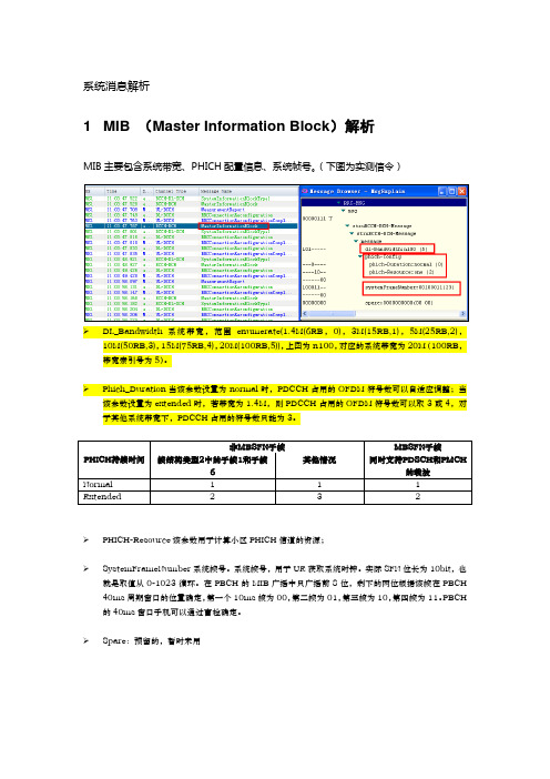
系统消息解析1 MIB (Master Information Block)解析MIB主要包含系统带宽、PHICH配置信息、系统帧号。
(下图为实测信令)➢DL_Bandwidth系统带宽,范围enumerate(1.4M(6RB,0),3M(15RB,1),5M(25RB,2),10M(50RB,3),15M(75RB,4),20M(100RB,5)),上图为n100,对应的系统带宽为20M(100RB,带宽索引号为5)。
➢Phich_Duration当该参数设置为normal时,PDCCH占用的OFDM符号数可以自适应调整;当该参数设置为extended时,若带宽为1.4M,则PDCCH占用的OFDM符号数可以取3或4,对于其他系统带宽下,PDCCH占用的符号数只能为3。
➢PHICH-Resource该参数用于计算小区PHICH信道的资源;➢SystemFrameNumber系统帧号。
系统帧号,用于UE获取系统时钟。
实际SFN位长为10bit,也就是取值从0-1023循环。
在PBCH的MIB广播中只广播前8位,剩下的两位根据该帧在PBCH 40ms周期窗口的位置确定,第一个10ms帧为00,第二帧为01,第三帧为10,第四帧为11。
PBCH 的40ms窗口手机可以通过盲检确定。
➢Spare:预留的,暂时未用2 SIB1 (System Information Block Type1)解析SIB1上主要传输评估UE能否接入小区的相关信息及其他系统消息的调度信息。
主要包括4部分:➢小区接入相关信息(cell Access Related Info)➢小区选择信息(cell Selection Info)➢调度信息(scheduling Info List)➢TDD配置信息(tdd-Config)SIB1消息解析(UE侧):RRC-MSG..msg....struBCCH-DL-SCH-Message......struBCCH-DL-SCH-Message........message..........c1............systemInformationBlockType1..............cellAccessRelatedInfo//小区接入相关信息................plmn-IdentityList//PLMN标识列表..................PLMN-IdentityInfo....................plmn-Identity ......................mcc//460 ........................MCC-MNC-Digit:0x4 (4) ........................MCC-MNC-Digit:0x6 (6) ........................MCC-MNC-Digit:0x0 (0) ......................mnc//00 ........................MCC-MNC-Digit:0x0 (0) ........................MCC-MNC-Digit:0x0 (0) ....................cellReservedForOperatorUse:notReserved (1) ................trackingAreaCode:11100(890C)//TAC跟踪区(890C)为16进制数,转换成十进制为35084,查TAC在该消息中可以查到,此条信元重要。
mds_user_guide

User GuideMDS11.6 Issue 270605 Rev 0NOTE: AVEVA Solutions has a policy of continuing product development: therefore, the information contained in this document may be subject to change without notice. AVEVA SOLUTIONS MAKES NO WARRANTY OF ANY KIND WITH REGARD TO THIS DOCUMENT, INCLUDING BUT NOT LIMITED TO, THE IMPLIED WARRANTIES OF MERCHANTABILITY AND FITNESS FOR A PARTICULAR PURPOSE. While every effort has been made to verify the accuracy of this document, AVEVA Solutions shall not be liable for errors contained herein or direct, indirect, special, incidental or consequential damages in connection with the furnishing, performance or use of this material.This manual provides documentation relating to products to which you may not have access or which may not be licensed to you. For further information on which Products are licensed to you, refer to your license conditions. Copyright 1991 through 2005 AVEVA Solutions LimitedAll rights reserved. No part of this document may be reproduced, stored in a retrieval system or transmitted, in any form or by any means, electronic, mechanical, photocopying, recording or otherwise, without prior written permission of AVEVA Solutions. The software programs described in this document are confidential information and proprietary products of AVEVA Solutions or its licensors.For details of AVEVA's worldwide sales and support offices, see our website at: MDS11.6 User GuideContents1 Introduction ...........................................................................................................11.1 1.2 1.3 1.4 About this User Guide .............................................................................................................. 1 Overview of the MDS application ............................................................................................. 1 Administrator’s role .................................................................................................................. 2 MDS catalogues and specifications ......................................................................................... 22Starting the application ........................................................................................32.1 Creating a multi discipline support ........................................................................................... 6 2.1.1 2.1.2 2.1.3 2.2 2.3 2.4 2.5 2.6 2.7 2.8 2.9 Create by Cursor ..................................................................................................... 14 Create by Clearance................................................................................................ 15 Create by Dimensions ............................................................................................. 16Changing the size of the steelwork ........................................................................................ 17 Adding a packing piece .......................................................................................................... 18 Creating and manipulating connections to external steelwork .............................................. 19 Ending the creation of a support ............................................................................................ 20 Modifying a support................................................................................................................ 21 Deleting a support .................................................................................................................. 25 Copying a support .................................................................................................................. 26 Modifying an ancillary type..................................................................................................... 272.10 Modifying ancillary dimensions .............................................................................................. 27 2.11 Modifying a support name...................................................................................................... 28 2.12 Viewing the application defaults............................................................................................. 29 2.13 Adding a drawing note ........................................................................................................... 30 2.14 Adding a support to the drawlist............................................................................................. 30 2.15 MDS administration options ................................................................................................... 30 2.15.1 Reloading defaults ................................................................................................... 31 2.16 Align a guide to a support ...................................................................................................... 32 2.17 Associate a pad with a shoe .................................................................................................. 32 2.18 Querying the size of an ancillary............................................................................................ 33 2.19 Special supports..................................................................................................................... 34 2.19.1 2.19.2 2.19.3 2.19.4 2.19.5 Creating a special support ....................................................................................... 34 Creating a special support from a combination of standards .................................. 36 Creating a project special support ........................................................................... 38 Creating a special SCTN from the copy section icon .............................................. 40 Including a section into a special support using the Include a Section into SpecialContents-iMDS11.6 User Guideicon .......................................................................................................................... 40 2.19.6 2.19.7 2.19.8 2.19.9 Creating a stiffener box in a special support using the Create a Stiffener Box icon 40 Modifying a stiffener box material or size from the Modify Stiffener Box Material/Size icon .......................................................................................................................... 41 Moving an HVAC project special joint or SCTN with the Move a Project Special Joint/SCTN icon ....................................................................................................... 42 Modifying a special section with the Modify Section icon........................................ 423 4Trunnions.............................................................................................................44 Hangers................................................................................................................484.1 4.2 4.3 4.4 Creating a hanger .................................................................................................................. 48 4.1.1 Using the filter buttons ............................................................................................. 50 Selecting a creation mode...................................................................................................... 52 Ending the creation of a hanger ............................................................................................. 54 Modifying a hanger................................................................................................................. 54 4.4.1 4.4.2 4.4.3 4.5 Rotating all hanger members................................................................................... 55 Rotating a hanger member ...................................................................................... 55 Additional modification options ................................................................................ 56Creating an MDS hanger using a manufacturer’s interface................................................... 605Branch reinforcements .......................................................................................615.1 Creating a branch reinforcement ........................................................................................... 616 7Preliminary supports ..........................................................................................63 Welding application ............................................................................................657.1 7.2 Creating a weld on a framework or special............................................................................ 65 Positioning welds on a framework or special pick ................................................................. 678 9Isometric material list control ............................................................................69 Data access control ............................................................................................709.1 9.2 9.3 Application entry..................................................................................................................... 70 Create mode........................................................................................................................... 70 Additional requirements for MDS with DACS......................................................................... 7110Application data sheets ......................................................................................72Contents-iiMDS11.6 User Guide11 12MDS Wizard .........................................................................................................73 MDS reports.........................................................................................................7412.1 Basic report ............................................................................................................................ 74 12.2 Extended report...................................................................................................................... 75 12.2.1 12.2.2 Extra run-time filter expressions .............................................................................. 75 Customised report headings.................................................................................... 76Contents-iiiMDS11.6 User Guide11.1IntroductionAbout this User GuideThis document provides guidance to the design engineer on how to create supports using the Multi Discipline Supports (MDS) application. It is assumed that the design engineer has a basic understanding of the program.1.2Overview of the MDS applicationThe MDS application allows you to create supports for piping, cable racks, and HVAC. It is highly interactive, enabling you to design supports with the minimum of effort. The MDS application is also highly configurable, allowing the administrator to define project-related defaults, to control the design of supports, and to determine the range and types of ancillary components that can be used on a project. The standard framework supports in the MDS application are designed using structural sections and are template driven. A default set of structural templates based on British Standard steelwork sections is supplied with the MDS application. Any relevant national standard for steelwork sections can be used by configuring the supplied templates. For further information refer to the Framework Template Administration Guide. If the templates supplied do not suit your project or company requirements, get your MDS administrator to configure them, or contact AVEVA Solutions to investigate your requirements and create a special. The requirement to add an extra member to an existing template configuration is an example of a special. The extra member would be designed as, or converted to, a special and then added to the template with the standard Beams and Columns application. Ancillaries are elements, such as u-bolts, bolt-on shoes, anchors, or slip-units, which are attached to pipes. Ancillaries associated with the template are those suitable for, or available with the standard. Ancillaries for cable trays and HVAC, sometimes referred to as fixings, are deemed to be the responsibility of the relevant contractor and are not dealt with in this application. The creation of every support follows this process: 1. Select a support type from a menu or icons. 2. Enter a name for the support. 3. Create a datum atta (attachment) and select an ancillary type. 4. Set distance and/or position for the datum atta. 5. Choose the steelwork from a list of available sizes. 6. Create using the required creation method. 7. Select miscellaneous options. 8. Select the packing if required. 9. Complete the process (the Integrity Checker runs automatically at this point).Draft1MDS11.6 User Guide1.3Administrator’s roleThe administrator is responsible for the initial setup of the default files and the design template database associated with the MDS application.1.4MDS catalogues and specificationsThe MDS application is supplied with a catalogue and specification. The range of bores and components in the catalogue are fixed. The /MDS specification contains all ancillary types, and the /MDF specification contains the SREF attachments for standard frameworks. The /MDP specification contains the preliminary support type available within the MDS application. The /RPAD-MDS-PLATE-MATERIAL specification contains the material used for reinforcing pad type supports. Caution: The catalogue and associated specifications must NOT be modified.Draft2MDS11.6 User Guide2Starting the application1. Start the Design General Application (default start-up). The Design General Application start-up form (Figure 1) is displayed.Figure 1 General Application form 2. Select Design>Multi Discipline Supports… from the main menu (Figure 2).Figure 2 Design pull-down menuDraft3MDS11.6 User GuideThe start-up form re-initialises to become the main menu bar (Figure 3), which includes all functions specific to the MDS module. The system tests for the existence of the design template database /MDS/TEMPLATES and the /MDS and /MDF specifications. If neither of these exists, MDS entry is stopped, an error message is displayed, and you re-enter the Design General Application. If this occurs, ask your administrator to add these databases to your MDB (Multiple Database).Figure 3 Main Menu Bar form Simultaneously, the application overlays a form (Figure 4) listing all valid zones found in the current MDB. The default file DES-SUPP-ID controls the selection of which zones are displayed. For more information on how these zones are selected, refer to the MDS Administration User Guide.Figure 4 Default Creation Zone form 3. Select a zone in which to create your support structures. Two tool bars (Figure 5) are located under the main menu bar.Draft4MDS11.6 User GuideIcons which control the general setup and display operations are positioned on the left. The icons to the tight of centre are short cuts to all the available menus in the MDS application. Place the cursor over each of these icons to display an associated tool tip. Note: Toolbars now conform to standard Windows operation and can be repositioned in a number of ways. Beware that some icons may be hidden if you re-arrange the toolbars. The hidden icons on any toolbar can be accessed using the drop-down arrow at the right-hand end of the toolbar.Figure 5 General setup and shortcut toolbars Each icon and its assigned action or purpose is listed in Table 1 below. Multi discipline supports Cable racking supports Anchors Variable hangers Guides and stops Specials Trunnions Branch reinforcements Modify support Preliminary support Defaults General supports HVAC supports Fixed hangers Constant hangers Slip units Springs Vessels supports Copy supports Delete support Lock/unlock support WizardReportsManualsTable 1 Menu shortcut iconsDraft52.1 Creating a multi discipline support1. Select the Create pull-down menu (Figure 6).Figure 6 Create menu2. Click on Multi Discipline Frame…. A form similar to the example shown in Figure 7 isdisplayed.Figure 7 Multi-discipline Frameworks selection formThis form contains all the available supports for the MDS application default file DES-SUPP-DEFS, which is located in the project default directory.You can also create support groups using the icon. Group names are identified by the suffix, [1]. Hangers can be added to the main framework support group and detailed as one entire MDS support drawing.Any unavailable support requires a different description to be displayed, or requires adifferent name to the standard name supplied. Such names can be modified in this file.Refer to the Administrators User Guide for further information.In the example shown in Figure 7, the prefix X has been added to all support default names.3. Enter a name as follows:a. Enter the name of the support to be created.If you enter a legal name in the Name field then click the OK button, the form becomes active. Notice that in Figure 7, no name is specified and so the OK button is inactive.or…b. Click on the AutoName button at the top of the form. An automatically generatedname is filled in (Figure 8) and the OK button is now active.Figure 8 Multi Discipline Frameworks selection form, with auto-naming4. Click on the required support type.Note:Do NOT click on OK at this time.At any time when the form shown in Figure 7 or Figure 8 is displayed, you can click on the View button to see the engineering drawing corresponding to the selected support. See the example in Figure 9.Figure 9 Engineering drawing for the selected support5. Right-click on the AutoName button and the button bar shown in Figure 10 is displayed.Figure 10 Initiate selecting a different naming file.6. Click on the Select Naming File… panel. The AutoNaming File form (Figure 11) isdisplayed. This allows you to select:a. a different AutoNaming file for the session,or…b. a different AutoNaming file set for the zone.Refer to the MDS Administration User Guide for further information.Note:Figure 8 remains displayed.Figure 11 AutoNaming File formYou can also select a zone, which is used to create all the support structures, by clicking on the Default Creation Zone button on the Multi Discipline Frames form.7. Select the support type required.8. Click on the OK button. The type is selected and the form closes. Refer to the MDSAdministration User Guide for further information.Example: Creating a support typeIn this example you will create support type XFT09, using the name FT09 1. Click on the OK button shown in Figure 8. A form similar to that shown in2.3. Figure 12 is displayed.Figure 12 XFT09 formSee section 2.6 for a descriptive overview of the icon functions.4. Ensure that the pipes, cable rack, or HVAC you need to support are added to the Drawlist,along with any other elements needed to create the support. This may include steelwork and panels, depending on the creation mode that is to be used. They must be added to the graphical view to be identified.5. Create the datum atta. This is the attachment on the first pipe that is associated with thesupport structure. This must be a pipe, not a cable rack or HVAC element.To create the datum atta select the Create datum support atta button at the top of the form. You are presented with the cursor so that you can identify a pipe. When you have done this, the Ancillary Selection form containing a filtered list of all the available ancillaries at the selected pipe bore, is displayed (Figure 13). These may be restricted for eachframework type. For more information refer to the MDS Administration User Guide.Figure 13 Ancillary Selection form6. Select the ancillary XAT16 (Bolt on Shoe) from the form. Click on the OK button. Theapplication now creates the pipe shoe on the selected pipe and positions it at the previous component or branch start, with a graphical tag of Datum for easy recognition. The Create Datum support Atta button is deactivated.7. Position the shoe on the pipe using:a. the Distance button, with a distance value placed in the text field next to it,or:..b. any of the Through button available options. These include; Through ID Cursor,Through Back Mark, and so on.8. Continue to add all the pipes, HVAC, and cable racks to the support. These can be addedThe application now positions the new attachments with respect to the datum atta.The example in Figure 14 shows two pipes, HVAC, and cable rack elements added to thesupport.Figure 14 Design screen 1Notice that the HVAC and cable rack support attachments have a ‘lollipop’ representation.This is because the fixings to the steelwork are regarded as supplied by the HVAC and cable rack contractor; no allowance is made for the selection of different fixings in the MDS application. The ‘lollipop’ representation is removed when the support is completed,returning to its original drawing level before the support was created. There are noobstruction properties associated with the lollipop representation and no clashes arereported.9. Choose the template required to create the support.10. Select the steelwork size icon .11. Select a template available from the list presented on the form (Figure 15). The template listshows all available templates. For this exercise, choose the second option, 80x80x10Angle, Internally Welded.Figure 15 Set Steelwork Size selection form12. Click Dismiss to access the selection and return to the Ancillary Selection form (Figure 13).13. Click on OK.There are three different options that you can use to create the steel framework:•Create by Cursor•Create by Clearance•Create by DimensionsYou will now create the framework with all three options and see what differences they make.2.1.1 Create by CursorOn the XFT09 form:1. Select the Create by Cursor icon. You are presented with the cursor and prompted from thestatus form to identify steelwork, boxes, or panels.2. Select the horizontal steelwork member parallel to the pipes on the left.3. Select the horizontal steelwork member to the right of the pipes.The application now creates the support using dimensions gained from the positions of theidentified steelwork. The view appears as shown in Figure 16. When complete, theapplication fills in all the dimensions with their correct values. These are stored against thesupport when it has finished, enabling future modifications of the support.Figure 16 Design screen 2Now add a cross member to support the HVAC and cable rack.4. Select the Add Cross Bar icon . You are presented with the cursor and asked to identifythe support attachment(s) to support with a cross bar.5. Identify the HVAC and cable rack ‘lollipop’.6. Click the Cancel button on the status form. The application creates the crossbar andpositions it at the correct elevation.Identify both attachments to which the cross will be attached. This information is used laterin the support Integrity Checker to check the packing distance between the cross bar andthe support attachment. The support Integrity Checker is executed whenever you press theOK button. The view is then as shown in Figure 17.Note:The elements to which the cross-beam is attached must be parallel to the piperun.Figure 17 Design screen 32.1.2 Create by ClearanceUsing the Create by Cursor method, two separate elements must be identified and theseelements must be parallel to the pipe run. Using the Create by Clearance method, only oneelement needs to be identified.1. Select the Create by Clearance icon. You are presented with the cursor to identify asteelwork member, box or, panel.2. Select the horizontal steelwork member that is perpendicular to, and above, the pipes.The application now creates the support using the dimensions gained from the position ofthe identified steelwork member. The clearances are calculated from the default values,obtained from the support Application Default form, and are used to calculate the positionsof the vertical members.These values and all other default values can be queried by displaying the MDS ApplicationDefaults form, from the Settings>Defaults>Applications menu item. For more informationon this and the other defaults used, refer to the MDS Administration User Guide.The application fills in all the dimensions with their correct values. The view is then asshown in Figure 18.MDS11.6 User Guide3 2Datum Pipe1ElevationFigure 18 Design screen 42.1.3 Create by DimensionsUse this method when the required steelwork is not yet entered into the 3D model, enabling you to continue working. 1. Enter the following dimensions in the MDS Framework form: Dimension 1 Dimension 2 Dimension 3 Dimension 4 = = = = 1300mm 350mm 1000mm 1100mmThe location of each dimension can be viewed by clicking on the View... button. This displays a plotfile with the dimensions shown. 2. Select the Create by Dimensions icon .The application now creates the support using the dimensions entered. The view is then as shown in Figure 19.Draft16MDS11.6 User Guide3 2Datum Pipe1ElevationFigure 19 Design screen 52.2Changing the size of the steelworkTo modify the size of the steelwork: 1. Select the Set Steelwork Size form (Figure 15). 2. Select the size required. The application recreates the support using the dimensions that are entered on the form. Try this by selecting option 4, “152 x 89 Channel Internally Welded”. The view is then as shown in Figure 20.3 2Datum Pipe1ElevationFigure 20 Design screen 5Draft17MDS11.6 User Guide2.3Adding a packing piecePacking pieces are used to make up height differences between the cross bar and support attachments. 1. Select the Add Packer icon from the MDS XFT09 form. You are presented with the cursor and a status line prompt to identify the support atta to add the packing piece to. The Packing Piece form (Figure 21) is displayed. 2. Fill in the form as required.Figure 21 Packing Piece formDraft18MDS11.6 User Guide2.4Creating and manipulating connections to external steelworkAfter the structural steelwork has been created, it may be necessary to connect it to external steelwork. To add a connection to external steelwork: 1. Select the Create Connections icon . This creates a connection only if the application knows the identity of the steelwork to connect to. If you used the Create by Cursor or Create by Clearance methods the connection to the external steelwork is made automatically. Note: It is essential that you have write access to create SNOD/SJOI elements on the necessary external steelwork.The SNOD is represented in the graphical view. The MDS application defaults control to the level at which joists can be made to the external steelwork. Refer to the MDS Administration User Guide for more details. 2. Select the Modify Joints icon available joints. . You are presented with a form that displays all the3. Select the joint for the joints connected to the external steelwork. If you have identified the external steelwork to connect to with either Create by Cursor or Create by Clearance, it is possible that the application will connect to the wrong Pline. This can happen in the case of the SCTN having floating Plines (X) (Figure 22a).RT0BFloating Pline XLT05TO5This is the Pline on the int. This is the Pline on the owning SCTN. X(a)X(b)Figure 22 Forced connection to SCTN with floating Plines You can force-connect the joint to a specific Pline (Figure 22b) by selecting the Force Connect joint icon . You are prompted to identify the required Pline using the cursor.Draft19。
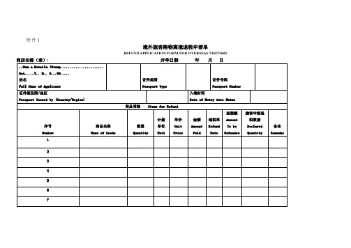
境外旅客购物离境退税申请单
证件类型
Passport Type
证件号码
Passport Number
证件签发国/地区
Passport Issued by (Country/Region)
入境时间
Date of Entry into China
商品明细 Items for Refund
旅客退税
申请
Tourist Application
1.退税方式.. 现金.......转账...开户行........... 银行账号:
Refun.Mode...Cas..... Ban.Transfe..Ban. Nam......... Accoun. No..........2.退税币种..... 人民.. 美....欧...日元
附件1
境外旅客购物离境退税申请单
REFUND APPLICATION FORM FOROVERSEASVISITORS
商店名称(章):开单日期:年月日
..Nam.o.Retaile.(Stamp....................... Dat.....Y.. M.. D...NO.....
姓名
Preferred Currency RMB□ USD□ EUR□ JPY□
3. 电话: 旅客签名:
Tel............. Applicant’. Signatur............ 日期.... ..日
........................................Dat...Y.. M.. D.
序号
Number
商品名称
Name of Goods
数量
Quantity