Surface Sensing and Classi cation for E cient Mobile Robot Navigation
ASTM D638 塑料 拉伸
Designation:D638–03Standard Test Method forTensile Properties of Plastics1This standard is issued under thefixed designation D638;the number immediately following the designation indicates the year of original adoption or,in the case of revision,the year of last revision.A number in parentheses indicates the year of last reapproval.A superscript epsilon(e)indicates an editorial change since the last revision or reapproval.This standard has been approved for use by agencies of the Department of Defense.1.Scope*1.1This test method covers the determination of the tensile properties of unreinforced and reinforced plastics in the form of standard dumbbell-shaped test specimens when tested under defined conditions of pretreatment,temperature,humidity,and testing machine speed.1.2This test method can be used for testing materials of any thickness up to14mm[0.55in.].However,for testing specimens in the form of thin sheeting,includingfilm less than 1.0mm[0.04in.]in thickness,Test Methods D882is the preferred test method.Materials with a thickness greater than 14mm[0.55in.]must be reduced by machining.1.3This test method includes the option of determining Poisson’s ratio at room temperature.N OTE1—This test method and ISO527-1are technically equivalent. N OTE2—This test method is not intended to cover precise physical procedures.It is recognized that the constant rate of crosshead movement type of test leaves much to be desired from a theoretical standpoint,that wide differences may exist between rate of crosshead movement and rate of strain between gage marks on the specimen,and that the testing speeds specified disguise important effects characteristic of materials in the plastic state.Further,it is realized that variations in the thicknesses of test specimens,which are permitted by these procedures,produce variations in the surface-volume ratios of such specimens,and that these variations may influence the test results.Hence,where directly comparable results are desired,all samples should be of equal thickness.Special additional tests should be used where more precise physical data are needed.N OTE3—This test method may be used for testing phenolic molded resin or laminated materials.However,where these materials are used as electrical insulation,such materials should be tested in accordance with Test Methods D229and Test Method D651.N OTE4—For tensile properties of resin-matrix composites reinforced with oriented continuous or discontinuous high modulus>20-GPa [>3.03106-psi]fibers,tests shall be made in accordance with Test Method D3039/D3039M.1.4Test data obtained by this test method are relevant and appropriate for use in engineering design.1.5The values stated in SI units are to be regarded as the standard.The values given in brackets are for information only.1.6This standard does not purport to address all of the safety concerns,if any,associated with its use.It is the responsibility of the user of this standard to establish appro-priate safety and health practices and determine the applica-bility of regulatory limitations prior to use.2.Referenced Documents2.1ASTM Standards:2D229Test Methods for Rigid Sheet and Plate Materials Used for Electrical InsulationD412Test Methods for Vulcanized Rubber and Thermo-plastic Elastomers—TensionD618Practice for Conditioning Plastics for TestingD651Test Method for Tensile Strength of Molded Electri-cal Insulating MaterialsD882Test Methods for Tensile Properties of Thin Plastic SheetingD883Terminology Relating to PlasticsD1822Test Method for Tensile-Impact Energy to Break Plastics and Electrical Insulating MaterialsD3039/D3039M Test Method for Tensile Properties of Polymer Matrix Composite MaterialsD4000Classification System for Specifying Plastic Mate-rialsD4066Classification System for Nylon Injection and Ex-trusion MaterialsD5947Test Methods for Physical Dimensions of Solid Plastic SpecimensE4Practices for Force Verification of Testing Machines E83Practice for Verification and Classification of Exten-someterE132Test Method for Poisson’s Ratio at Room Tempera-tureE691Practice for Conducting an Interlaboratory Study to Determine the Precision of a Test Method2.2ISO Standard:31This test method is under the jurisdiction of ASTM Committee D20on Plastics and is the direct responsibility of Subcommittee D20.10on Mechanical Properties.Current edition approved December1,2003.Published January2004.Originally approved st previous edition approved in2002as D638-02a.2For referenced ASTM standards,visit the ASTM website,,or contact ASTM Customer Service at service@.For Annual Book of ASTM Standards volume information,refer to the standard’s Document Summary page on the ASTM website.3Available from American National Standards Institute(ANSI),25W.43rd St., 4th Floor,New York,NY10036.1*A Summary of Changes section appears at the end of this standard. Copyright©ASTM International,100Barr Harbor Drive,PO Box C700,West Conshohocken,PA19428-2959,United States.ISO527-1Determination of Tensile Properties3.Terminology3.1Definitions—Definitions of terms applying to this test method appear in Terminology D883and Annex A2.4.Significance and Use4.1This test method is designed to produce tensile property data for the control and specification of plastic materials.These data are also useful for qualitative characterization and for research and development.For many materials,there may be a specification that requires the use of this test method,but with some procedural modifications that take precedence when adhering to the specification.Therefore,it is advisable to refer to that material specification before using this test method. Table1in Classification D4000lists the ASTM materials standards that currently exist.4.2Tensile properties may vary with specimen preparation and with speed and environment of testing.Consequently, where precise comparative results are desired,these factors must be carefully controlled.4.2.1It is realized that a material cannot be tested without also testing the method of preparation of that material.Hence, when comparative tests of materials per se are desired,the greatest care must be exercised to ensure that all samples are prepared in exactly the same way,unless the test is to include the effects of sample preparation.Similarly,for referee pur-poses or comparisons within any given series of specimens, care must be taken to secure the maximum degree of unifor-mity in details of preparation,treatment,and handling.4.3Tensile properties may provide useful data for plastics engineering design purposes.However,because of the high degree of sensitivity exhibited by many plastics to rate of straining and environmental conditions,data obtained by this test method cannot be considered valid for applications involv-ing load-time scales or environments widely different from those of this test method.In cases of such dissimilarity,no reliable estimation of the limit of usefulness can be made for most plastics.This sensitivity to rate of straining and environ-ment necessitates testing over a broad load-time scale(includ-ing impact and creep)and range of environmental conditions if tensile properties are to suffice for engineering design pur-poses.N OTE5—Since the existence of a true elastic limit in plastics(as in many other organic materials and in many metals)is debatable,the propriety of applying the term“elastic modulus”in its quoted,generally accepted definition to describe the“stiffness”or“rigidity”of a plastic has been seriously questioned.The exact stress-strain characteristics of plastic materials are highly dependent on such factors as rate of application of stress,temperature,previous history of specimen,etc.However,stress-strain curves for plastics,determined as described in this test method, almost always show a linear region at low stresses,and a straight line drawn tangent to this portion of the curve permits calculation of an elastic modulus of the usually defined type.Such a constant is useful if its arbitrary nature and dependence on time,temperature,and similar factors are realized.4.4Poisson’s Ratio—When uniaxial tensile force is applied to a solid,the solid stretches in the direction of the applied force(axially),but it also contracts in both dimensions lateral to the applied force.If the solid is homogeneous and isotropic,and the material remains elastic under the action of the applied force,the lateral strain bears a constant relationship to the axial strain.This constant,called Poisson’s ratio,is defined as the negative ratio of the transverse(negative)to axial strain under uniaxial stress.4.4.1Poisson’s ratio is used for the design of structures in which all dimensional changes resulting from the application of force need to be taken into account and in the application of the generalized theory of elasticity to structural analysis.N OTE6—The accuracy of the determination of Poisson’s ratio is usually limited by the accuracy of the transverse strain measurements because the percentage errors in these measurements are usually greater than in the axial strain measurements.Since a ratio rather than an absolute quantity is measured,it is only necessary to know accurately the relative value of the calibration factors of the extensometers.Also,in general,the value of the applied loads need not be known accurately.5.Apparatus5.1Testing Machine—A testing machine of the constant-rate-of-crosshead-movement type and comprising essentially the following:5.1.1Fixed Member—Afixed or essentially stationary member carrying one grip.5.1.2Movable Member—A movable member carrying a second grip.5.1.3Grips—Grips for holding the test specimen between thefixed member and the movable member of the testing machine can be either thefixed or self-aligning type.5.1.3.1Fixed grips are rigidly attached to thefixed and movable members of the testing machine.When this type of grip is used extreme care should be taken to ensure that the test specimen is inserted and clamped so that the long axis of the test specimen coincides with the direction of pull through the center line of the grip assembly.5.1.3.2Self-aligning grips are attached to thefixed and movable members of the testing machine in such a manner that they will move freely into alignment as soon as any load is applied so that the long axis of the test specimen will coincide with the direction of the applied pull through the center line of the grip assembly.The specimens should be aligned as per-fectly as possible with the direction of pull so that no rotary motion that may induce slippage will occur in the grips;there is a limit to the amount of misalignment self-aligning grips will accommodate.5.1.3.3The test specimen shall be held in such a way that slippage relative to the grips is prevented insofar as possible. Grip surfaces that are deeply scored or serrated with a pattern similar to those of a coarse single-cutfile,serrations about2.4 mm[0.09in.]apart and about1.6mm[0.06in.]deep,have been found satisfactory for most thermoplastics.Finer serra-tions have been found to be more satisfactory for harder plastics,such as the thermosetting materials.The serrations should be kept clean and sharp.Breaking in the grips may occur at times,even when deep serrations or abraded specimen surfaces are used;other techniques must be used in these cases. Other techniques that have been found useful,particularly with smooth-faced grips,are abrading that portion of the surface of the specimen that will be in the grips,and interposingthinpieces of abrasive cloth,abrasive paper,or plastic,or rubber-coated fabric,commonly called hospital sheeting,between the specimen and the grip surface.No.80double-sided abrasive paper has been found effective in many cases.An open-mesh fabric,in which the threads are coated with abrasive,has also been effective.Reducing the cross-sectional area of the speci-men may also be effective.The use of special types of grips is sometimes necessary to eliminate slippage and breakage in the grips.5.1.4Drive Mechanism—A drive mechanism for imparting to the movable member a uniform,controlled velocity with respect to the stationary member,with this velocity to be regulated as specified in Section8.5.1.5Load Indicator—A suitable load-indicating mecha-nism capable of showing the total tensile load carried by the test specimen when held by the grips.This mechanism shall be essentially free of inertia lag at the specified rate of testing and shall indicate the load with an accuracy of61%of the indicated value,or better.The accuracy of the testing machine shall be verified in accordance with Practices E4.N OTE7—Experience has shown that many testing machines now in use are incapable of maintaining accuracy for as long as the periods between inspection recommended in Practices E4.Hence,it is recommended that each machine be studied individually and verified as often as may be found necessary.It frequently will be necessary to perform this function daily.5.1.6Thefixed member,movable member,drive mecha-nism,and grips shall be constructed of such materials and in such proportions that the total elastic longitudinal strain of the system constituted by these parts does not exceed1%of the total longitudinal strain between the two gage marks on the test specimen at any time during the test and at any load up to the rated capacity of the machine.5.1.7Crosshead Extension Indicator—A suitable extension indicating mechanism capable of showing the amount of change in the separation of the grips,that is,crosshead movement.This mechanism shall be essentially free of inertial lag at the specified rate of testing and shall indicate the crosshead movement with an accuracy of610%of the indicated value.5.2Extension Indicator(extensometer)—A suitable instru-ment shall be used for determining the distance between two designated points within the gage length of the test specimen as the specimen is stretched.For referee purposes,the extensom-eter must be set at the full gage length of the specimen,as shown in Fig.1.It is desirable,but not essential,that this instrument automatically record this distance,or any change in it,as a function of the load on the test specimen or of the elapsed time from the start of the test,or both.If only the latter is obtained,load-time data must also be taken.This instrument shall be essentially free of inertia at the specified speed of testing.Extensometers shall be classified and their calibration periodically verified in accordance with Practice E83.5.2.1Modulus-of-Elasticity Measurements—For modulus-of-elasticity measurements,an extensometer with a maximum strain error of0.0002mm/mm[in./in.]that automatically and continuously records shall be used.An extensometer classified by Practice E83as fulfilling the requirements of a B-2classification within the range of use for modulus measure-ments meets this requirement.5.2.2Low-Extension Measurements—For elongation-at-yield and low-extension measurements(nominally20%or less),the same above extensometer,attenuated to20%exten-sion,may be used.In any case,the extensometer system must meet at least Class C(Practice E83)requirements,which include afixed strain error of0.001strain or61.0%of the indicated strain,whichever is greater.5.2.3High-Extension Measurements—For making mea-surements at elongations greater than20%,measuring tech-niques with error no greater than610%of the measured value are acceptable.5.2.4Poisson’s Ratio—Bi-axial extensometer or axial and transverse extensometers capable of recording axial strain and transverse strain simultaneously.The extensometers shall be capable of measuring the change in strains with an accuracy of 1%of the relevant value or better.N OTE8—Strain gages can be used as an alternative method to measure axial and transverse strain;however,proper techniques for mounting strain gages are crucial to obtaining accurate data.Consult strain gage suppliers for instruction and training in these special techniques.5.3Micrometers—Apparatus for measuring the width and thickness of the test specimen shall comply with the require-ments of Test Method D5947.6.Test Specimens6.1Sheet,Plate,and Molded Plastics:6.1.1Rigid and Semirigid Plastics—The test specimen shall conform to the dimensions shown in Fig. 1.The Type I specimen is the preferred specimen and shall be used where sufficient material having a thickness of7mm[0.28in.]or less is available.The Type II specimen may be used when a material does not break in the narrow section with the preferred Type I specimen.The Type V specimen shall be used where only limited material having a thickness of4mm[0.16in.]or less is available for evaluation,or where a large number of specimens are to be exposed in a limited space(thermal and environmental stability tests,etc.).The Type IV specimen should be used when direct comparisons are required between materials in different rigidity cases(that is,nonrigid and semirigid).The Type III specimen must be used for all materials with a thickness of greater than7mm[0.28in.]but not more than14mm[0.55in.].6.1.2Nonrigid Plastics—The test specimen shall conform to the dimensions shown in Fig.1.The Type IV specimen shall be used for testing nonrigid plastics with a thickness of4mm [0.16in.]or less.The Type III specimen must be used for all materials with a thickness greater than7mm[0.28in.]but not more than14mm[0.55in.].6.1.3Reinforced Composites—The test specimen for rein-forced composites,including highly orthotropic laminates, shall conform to the dimensions of the Type I specimen shown in Fig.1.6.1.4Preparation—Test specimens shall be prepared by machining operations,or die cutting,from materials in sheet, plate,slab,or similar form.Materials thicker than14mm[0.55Specimen Dimensions for Thickness,T ,mm [in.]ADimensions (see drawings)7[0.28]or under Over 7to 14[0.28to 0.55],incl4[0.16]or under Tolerances Type I Type II Type III Type IV B Type V C ,D W —Width of narrow section E ,F 13[0.50]6[0.25]19[0.75]6[0.25] 3.18[0.125]60.5[60.02]B ,C L —Length of narrow section 57[2.25]57[2.25]57[2.25]33[1.30]9.53[0.375]60.5[60.02]C WO —Width overall,min G 19[0.75]19[0.75]29[1.13]19[0.75]...+6.4[+0.25]WO —Width overall,min G ............9.53[0.375]+3.18[+0.125]LO —Length overall,min H 165[6.5]183[7.2]246[9.7]115[4.5]63.5[2.5]no max [no max]G —Gage length I 50[2.00]50[2.00]50[2.00]...7.62[0.300]60.25[60.010]C G —Gage length I.........25[1.00]...60.13[60.005]D —Distance between grips 115[4.5]135[5.3]115[4.5]65[2.5]J 25.4[1.0]65[60.2]R —Radius of fillet76[3.00]76[3.00]76[3.00]14[0.56]12.7[0.5]61[60.04]C RO —Outer radius (Type IV).........25[1.00]...61[60.04]AThickness,T ,shall be 3.260.4mm [0.1360.02in.]for all types of molded specimens,and for other Types I and II specimens where possible.If specimens are machined from sheets or plates,thickness,T ,may be the thickness of the sheet or plate provided this does not exceed the range stated for the intended specimen type.For sheets of nominal thickness greater than 14mm [0.55in.]the specimens shall be machined to 1460.4mm [0.5560.02in.]in thickness,for use with the Type III specimen.For sheets of nominal thickness between 14and 51mm [0.55and 2in.]approximately equal amounts shall be machined from each surface.For thicker sheets both surfaces of the specimen shall be machined,and the location of the specimen with reference to the original thickness of the sheet shall be noted.Tolerances on thickness less than 14mm [0.55in.]shall be those standard for the grade of material tested.BFor the Type IV specimen,the internal width of the narrow section of the die shall be 6.0060.05mm [0.25060.002in.].The dimensions are essentially those of Die C in Test Methods D 412.CThe Type V specimen shall be machined or die cut to the dimensions shown,or molded in a mold whose cavity has these dimensions.The dimensions shall be:W =3.1860.03mm [0.12560.001in.],L =9.5360.08mm [0.37560.003in.],G =7.6260.02mm [0.30060.001in.],and R =12.760.08mm [0.50060.003in.].The other tolerances are those in the table.DSupporting data on the introduction of the L specimen of Test Method D 1822as the Type V specimen are available from ASTM Headquarters.Request RR:D20-1038.EThe width at the center W c shall be +0.00mm,−0.10mm [+0.000in.,−0.004in.]compared with width W at other parts of the reduced section.Any reduction in W at the center shall be gradual,equally on each side so that no abrupt changes in dimension result.FFor molded specimens,a draft of not over 0.13mm [0.005in.]may be allowed for either Type I or II specimens 3.2mm [0.13in.]in thickness,and this should be taken into account when calculating width of the specimen.Thus a typical section of a molded Type I specimen,having the maximum allowable draft,could be as follows:GOverall widths greater than the minimum indicated may be desirable for some materials in order to avoid breaking in the grips.HOverall lengths greater than the minimum indicated may be desirable either to avoid breaking in the grips or to satisfy special test requirements.ITest marks or initial extensometer span.JWhen self-tightening grips are used,for highly extensible polymers,the distance between grips will depend upon the types of grips used and may not be critical if maintained uniform once chosen.FIG.1Tension Test Specimens for Sheet,Plate,and Molded Plasticsin.]must be machined to 14mm [0.55in.]for use as Type III specimens.Specimens can also be prepared by molding the material to be tested.N OTE 9—Test results have shown that for some materials such as glasscloth,SMC,and BMC laminates,other specimen types should be considered to ensure breakage within the gage length of the specimen,as mandated by 7.3.N OTE 10—When preparing specimens from certain composite lami-nates such as woven roving,or glass cloth,care must be exercised in cutting the specimens parallel to the reinforcement.The reinforcement will be significantly weakened by cutting on a bias,resulting in lower laminate properties,unless testing of specimens in a direction other than parallel with the reinforcement constitutes a variable being studied.N OTE 11—Specimens prepared by injection molding may have different tensile properties than specimens prepared by machining or die-cutting because of the orientation induced.This effect may be more pronounced in specimens with narrow sections.6.2Rigid Tubes —The test specimen for rigid tubes shall be as shown in Fig.2.The length,L ,shall be as shown in the table in Fig.2.A groove shall be machined around the outside of the specimen at the center of its length so that the wall section after machining shall be 60%of the original nominal wall thick-ness.This groove shall consist of a straight section 57.2mm [2.25in.]in length with a radius of 76mm [3in.]at each end joining it to the outside diameter.Steel or brass plugs having diameters such that they will fit snugly inside the tube and having a length equal to the full jaw length plus 25mm [1in.]shall be placed in the ends of the specimens to prevent crushing.They can be located conveniently in the tube by separating and supporting them on a threaded metal rod.Details of plugs and test assembly are shown in Fig.2.6.3Rigid Rods —The test specimen for rigid rods shall be as shown in Fig.3.The length,L ,shall be as shown in the table in Fig.3.A groove shall be machined around the specimen at the center of its length so that the diameter of the machined portion shall be 60%of the original nominal diameter.This groove shall consist of a straight section 57.2mm [2.25in.]in length with a radius of 76mm [3in.]at each end joining it to the outside diameter.6.4All surfaces of the specimen shall be free of visible flaws,scratches,or imperfections.Marks left by coarse ma-chining operations shall be carefully removed with a fine file or abrasive,and the filed surfaces shall then be smoothed with abrasive paper (No.00or finer).The finishing sanding strokes shall be made in a direction parallel to the long axis of the test specimen.All flash shall be removed from a molded specimen,taking great care not to disturb the molded surfaces.In machining a specimen,undercuts that would exceed the dimensional tolerances shown in Fig.1shall be scrupulously avoided.Care shall also be taken to avoid other common machining errors.6.5If it is necessary to place gage marks on the specimen,this shall be done with a wax crayon or India ink that will not affect the material being tested.Gage marks shall not be scratched,punched,or impressed on the specimen.6.6When testing materials that are suspected of anisotropy,duplicate sets of test specimens shall be prepared,having their long axes respectively parallel with,and normal to,the suspected direction of anisotropy.7.Number of Test Specimens7.1Test at least five specimens for each sample in the case of isotropicmaterials.DIMENSIONS OF TUBE SPECIMENSNominal Wall ThicknessLength of Radial Sections,2R.S.Total CalculatedMinimum Length of SpecimenStandard Length,L ,of Specimen to Be Used for 89-mm [3.5-in.]Jaws Amm [in.]0.79[1⁄32]13.9[0.547]350[13.80]381[15]1.2[3⁄64]17.0[0.670]354[13.92]381[15]1.6[1⁄16]19.6[0.773]356[14.02]381[15]2.4[3⁄32]24.0[0.946]361[14.20]381[15]3.2[1⁄8]27.7[1.091]364[14.34]381[15]4.8[3⁄16]33.9[1.333]370[14.58]381[15]6.4[1⁄4]39.0[1.536]376[14.79]400[15.75]7.9[5⁄16]43.5[1.714]380[14.96]400[15.75]9.5[3⁄8]47.6[1.873]384[15.12]400[15.75]11.1[7⁄16]51.3[2.019]388[15.27]400[15.75]12.7[1⁄2]54.7[2.154]391[15.40]419[16.5]AFor other jaws greater than 89mm [3.5in.],the standard length shall be increased by twice the length of the jaws minus 178mm [7in.].The standard length permits a slippage of approximately 6.4to 12.7mm [0.25to 0.50in.]in each jaw while maintaining the maximum length of the jaw grip.FIG.2Diagram Showing Location of Tube Tension TestSpecimens in TestingMachine7.2Test ten specimens,five normal to,and five parallel with,the principle axis of anisotropy,for each sample in the case of anisotropic materials.7.3Discard specimens that break at some flaw,or that break outside of the narrow cross-sectional test section (Fig.1,dimension “L”),and make retests,unless such flaws constitute a variable to be studied.N OTE 12—Before testing,all transparent specimens should be inspected in a polariscope.Those which show atypical or concentrated strain patterns should be rejected,unless the effects of these residual strains constitute a variable to be studied.8.Speed of Testing8.1Speed of testing shall be the relative rate of motion of the grips or test fixtures during the test.The rate of motion of the driven grip or fixture when the testing machine is running idle may be used,if it can be shown that the resulting speed of testing is within the limits of variation allowed.8.2Choose the speed of testing from Table 1.Determine this chosen speed of testing by the specification for the material being tested,or by agreement between those concerned.When the speed is not specified,use the lowest speed shown in Table 1for the specimen geometry being used,which gives rupture within 1⁄2to 5-min testing time.8.3Modulus determinations may be made at the speed selected for the other tensile properties when the recorder response and resolution are adequate.8.4The speed of testing for Poisson’s ratio determination shall be 5mm/min.9.Conditioning9.1Conditioning —Condition the test specimens at 2362°C [73.463.6°F]and 5065%relative humidity for not less than 40h prior to test in accordance with Procedure A of Practice D 618,unless otherwise specified by contract or the relevant ASTM material specification.Reference pre-test con-ditioning,to settle disagreements,shall apply tolerances of 61°C [1.8°F]and 62%relative humidity.9.2Test Conditions —Conduct the tests at 2362°C [73.463.6°F]and 5065%relative humidity,unless otherwise specified by contract or the relevant ASTM material specifica-tion.Reference testing conditions,to settle disagreements,shall apply tolerances of 61°C [1.8°F]and 62%relativehumidity.DIMENSIONS OF ROD SPECIMENSNominal Diam-eter Length of RadialSections,2R.S.Total CalculatedMinimumLength of SpecimenStandard Length,L ,ofSpecimen to Be Usedfor 89-mm [31⁄2-in.]Jaws A mm [in.]3.2[1⁄8]19.6[0.773]356[14.02]381[15]4.7[1⁄16]24.0[0.946]361[14.20]381[15]6.4[1⁄4]27.7[1.091]364[14.34]381[15]9.5[3⁄8]33.9[1.333]370[14.58]381[15]12.7[1⁄2]39.0[1.536]376[14.79]400[15.75]15.9[5⁄8]43.5[1.714]380[14.96]400[15.75]19.0[3⁄4]47.6[1.873]384[15.12]400[15.75]22.2[7⁄8]51.5[2.019]388[15.27]400[15.75]25.4[1]54.7[2.154]391[15.40]419[16.5]31.8[11⁄4]60.9[2.398]398[15.65]419[16.5]38.1[11⁄2]66.4[2.615]403[15.87]419[16.5]42.5[13⁄4]71.4[2.812]408[16.06]419[16.5]50.8[2]76.0[2.993]412[16.24]432[17]AFor other jaws greater than 89mm [3.5in.],the standard length shall be increased by twice the length of the jaws minus 178mm [7in.].The standard length permits a slippage of approximately 6.4to 12.7mm [0.25to 0.50in.]in each jaw while maintaining the maximum length of the jaw grip.FIG.3Diagram Showing Location of Rod Tension Test Specimenin Testing MachineTABLE 1Designations for Speed of Testing AClassification B Specimen TypeSpeed of Testing,mm/min [in./min]Nominal Strain C Rate atStart of Test,mm/mm·min [in./in.·min]Rigid and SemirigidI,II,III rods and tubes5[0.2]625%0.150[2]610%1500[20]610%10IV5[0.2]625%0.1550[2]610% 1.5500[20]610%15V1[0.05]625%0.110[0.5]625%1100[5]625%10Nonrigid III 50[2]610%1500[20]610%10IV50[2]610% 1.5500[20]610%15ASelect the lowest speed that produces rupture in 1⁄2to 5min for the specimen geometry being used (see 8.2).BSee Terminology D 883for definitions.CThe initial rate of straining cannot be calculated exactly for dumbbell-shaped specimens because of extension,both in the reduced section outside the gage length and in the fillets.This initial strain rate can be measured from the initial slope of the tensile strain-versus-timediagram.。
Parker Jet-Pipe 电击流控制伺服阀说明书

Care and handling guide
The care and handling of Parker Jet-Pipe® servovalves
Table of contents:
Introduction................................................................................ 1 Principle of operation of the Jet-Pipe® servovalve .............. 2 - 3 A clean system can prolong servovalve life.......................... 4 - 5 Installation ............................................................................ 6 - 7 Maintenance.......................................................................... 8 - 9 Field repair........................................................................ 10 - 11 Repair don’ts............................................................................ 12 Returning servovalves and service ......................................... 13
asme viii Division 1appendix12

Division 1VIII VIIIDivision 12004 ASMEBOILER &PRESSUREVESSEL CODEAN INTERNA TIONAL CODERULES FORCONSTRUCTION OFPRESSURE VESSELSMANDATORY APPENDIX 12ULTRASONIC EXAMINA TION OF WELDS (UT)12-1 SCOPE(a) This Appendix describes methods which shall beemployed when ultrasonic examination of welds is speci-fied in this Division.(b) Article 4 of Section V shall be applied for detailrequirements in methods, procedures and qualifications,unless otherwise specified in this Appendix.(c) Ultrasonic examination shall be performed in accordance with a written procedu re, certified by the Manufacturer to be in accordance with the requirements of T-150 of Section V.12-2 CERTIFICATION OF COMPETENCE OF NONDESTRUCTIVE EXAMINERThe Manufacturer shall certify that personnel per-forming and evaluating ultrasonic examinations required by this Division have been qualified and certified in accor-dance with their employer’s written practice. SNT-TC-1A1shall be used as a guideline for employers to establish their written practice for qualification and certification of their personnel. Alternatively, the ASNT Central Certifi-cation Program (ACCP)1or CP-1891 may be used to fulfill the examination and demonstration requirements of SNT-TC-1A and the employer’s written practice. Pro-visions for training, experience, qualification, and certifi-cation of NDE personnel shall be described in the Manufacturer’s Quality Control System (see Appendix 10).12-3 ACCEPTANCE–REJECTION STANDARDSThese Standards shall apply unless other standards are specified for specific applications within this Division.1 Imperfections which produce a response greater than 20% of the reference level shall be investigated to the extent that the operator can determine the shape, identity, and location of all such imperfections and evaluate them in terms of the acceptance standards given in (a) and (b)below.(a) Indications characterized as cracks, lack of fusion, or incomplete penetration are unacceptable regardless of length.(b) Other imperfections are unacceptable if the indica- tions exceed the reference level amplitude and have lengths which exceed:(1)1⁄4 in. (6 mm) for t up to 3⁄4 in. (19 mm);(2)1⁄3t for t from 3⁄4 in. to 21⁄4 in. (19 mm to 57 mm);(3)3⁄4 in. (19 mm) for t over 21⁄4 in. (57 mm).where t is the thickness of the weld excluding any allow-able reinforcement. For a butt weld joining two members having different thicknesses at the weld, t is the thinner of these two thicknesses. If a full penetration weld includes a fillet weld, the thickness of the throat of the fillet shall be included in t.12-4 REPORT OF EXAMINATIONThe Manufacturer shall prepare a report of the ultra-sonic examination and a copy of this report shall be retained by the Manufacturer until the Manufacturer’s Data Report has been signed by the Inspector. The report shall contain the information required by Section V. In addition, a record of repaired areas shall be noted as well as the results of the reexamination of the repaired areas.The Manufacturer shall also maintain a record of all reflections from uncorrected areas having responses that exceed 50%of the reference level. This record shall locate each area, the response level, the dimensions, the depth below the surface, and the classification。
NVIDIA Capture SDK Sample Description Document 201

2.9 NvFBCEnableAPI . . . . . . . . . . . . . . . . . . . . . . . . . . . . . . . . . . . . . . . . . . . . 11
2.10 NvFBCToSys . . . . . . . . . . . . . . . . . . . . . . . . . . . . . . . . . . . . . . . . . . . . . . . 12
4
Module Documentation
2.2 NvFBCCudaNvEnc
This sample demonstrates how to use the NvFBCToCuda interface to copy the desktop into a CUDA buffer. From the CUDA buffer, this is then mapped directly to NVENC, where the NVENC hardware video encoder can encode the stream. We recommend that developers use the NVIDIA Video Codec to utilize the NVENC hardware video Encoder. This sample provides a useful wrapper class around the NVENC API, in Encoder.h.
Reader.h: Declares the Reader class, this class is simply a wrapper around the NVENC reader API.
一种基于区域自适应的非局部均值(Nonlocal Means)图像去噪方法
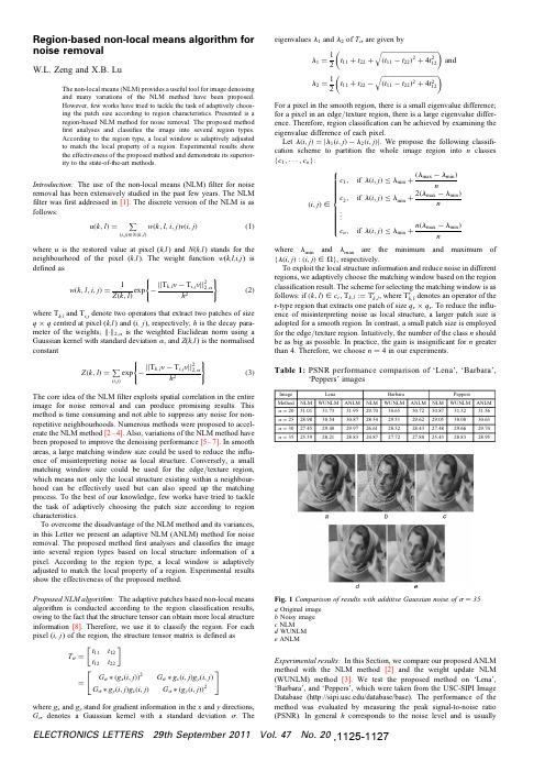
Region-based non-local means algorithm for noise removalW.L.Zeng and X.B.LuThe non-local means (NLM)provides a useful tool for image denoising and many variations of the NLM method have been proposed.However,few works have tried to tackle the task of adaptively choos-ing the patch size according to region characteristics.Presented is a region-based NLM method for noise removal.The proposed method first analyses and classifies the image into several region types.According to the region type,a local window is adaptively adjusted to match the local property of a region.Experimental results show the effectiveness of the proposed method and demonstrate its superior-ity to the state-of-the-art methods.Introduction:The use of the non-local means (NLM)filter for noise removal has been extensively studied in the past few years.The NLM filter was first addressed in [1].The discrete version of the NLM is as follows:u (k ,l )=(i ,j )[N (k ,l )w (k ,l ,i ,j )v (i ,j )(1)where u is the restored value at pixel (k,l )and N (k,l )stands for theneighbourhood of the pixel (k,l ).The weight function w (k,l,i,j )is defined asw (k ,l ,i ,j )=1exp −||T k ,l v −T i ,j v ||22,a(2)where T k,l and T i,j denote two operators that extract two patches of sizeq ×q centred at pixel (k,l )and (i,j ),respectively;h is the decay para-meter of the weights; . 2,a is the weighted Euclidean norm using a Gaussian kernel with standard deviation a ,and Z (k,l )is the normalised constantZ (k ,l )= (i ,j )exp −||T k ,l v −T i ,j v ||22,ah 2(3)The core idea of the NLM filter exploits spatial correlation in the entireimage for noise removal and can produce promising results.This method is time consuming and not able to suppress any noise for non-repetitive neighbourhoods.Numerous methods were proposed to accel-erate the NLM method [2–4].Also,variations of the NLM method have been proposed to improve the denoising performance [5–7].In smooth areas,a large matching window size could be used to reduce the influ-ence of misinterpreting noise as local structure.Conversely,a small matching window size could be used for the edge /texture region,which means not only the local structure existing within a neighbour-hood can be effectively used but can also speed up the matching process.To the best of our knowledge,few works have tried to tackle the task of adaptively choosing the patch size according to region characteristics.To overcome the disadvantage of the NLM method and its variances,in this Letter we present an adaptive NLM (ANLM)method for noise removal.The proposed method first analyses and classifies the image into several region types based on local structure information of a pixel.According to the region type,a local window is adaptively adjusted to match the local property of a region.Experimental results show the effectiveness of the proposed method.Proposed NLM algorithm:The adaptive patches based non-local means algorithm is conducted according to the region classification results,owing to the fact that the structure tensor can obtain more local structure information [8].Therefore,we use it to classify the region.For each pixel (i,j )of the region,the structure tensor matrix is defined asT s =t 11t 12t 12t 22 =G s ∗(g x (i ,j ))2G s ∗g x (i ,j )g y (i ,j )G s ∗g y (i ,j )g x (i ,j )G s ∗(g y (i ,j ))2where g x and g y stand for gradient information in the x and y directions,G s denotes a Gaussian kernel with a standard deviation s .Theeigenvalues l 1and l 2of T s are given byl 1=12t 11+t 22+ (t 11−t 22)2+4t 212 and l 2=1t 11+t 22− (t 11−t 22)2+4t 212 For a pixel in the smooth region,there is a small eigenvalue difference;for a pixel in an edge /texture region,there is a large eigenvalue differ-ence.Therefore,region classification can be achieved by examining the eigenvalue difference of each pixel.Let l (i ,j )=|l 1(i ,j )−l 2(i ,j )|.We propose the following classifi-cation scheme to partition the whole image region into n classes {c 1,···,c n }:(i ,j )[c 1,if l (i ,j )≤l min +(l max −l min )n c 2,if l (i ,j )≤l min +2(l max −l min )n ...c n ,if l (i ,j )≤l min +n (l max −l min )n ⎧⎪⎪⎪⎪⎪⎪⎪⎪⎨⎪⎪⎪⎪⎪⎪⎪⎪⎩where l min and l max are the minimum and maximum of {l (i ,j ):(i ,j )[V },respectively.To exploit the local structure information and reduce noise in different regions,we adaptively choose the matching window based on the region classification result.The scheme for selecting the matching window is asfollows:if (k ,l )[c r ,T k ,l :=T r k ,l ,where T rk ,l denotes an operator of the r-type region that extracts one patch of size q r ×q r .To reduce the influ-ence of misinterpreting noise as local structure,a larger patch size is adopted for a smooth region.In contrast,a small patch size is employed for the edge /texture region.Intuitively,the number of the class n should be as big as possible.In practice,the gain is insignificant for n greater than 4.Therefore,we choose n ¼4in our experiments.Table 1:PSNR performance comparison of ‘Lena’,‘Barbara’,‘Peppers’imagesFig.1Comparison of results with additive Gaussian noise of s ¼35a Original image b Noisy image c NLM d WUNLM e ANLMExperimental results:In this Section,we compare our proposed ANLM method with the NLM method [2]and the weight update NLM (WUNLM)method [3].We test the proposed method on ‘Lena’,‘Barbara’,and ‘Peppers’,which were taken from the USC-SIPI Image Database (/database/base).The performance of the method was evaluated by measuring the peak signal-to-noise ratio (PSNR).In general h corresponds to the noise level and is usuallyELECTRONICS LETTERS 29th September 2011Vol.47No.20,1125-1127fixed to the standard deviation of the noise.The size of the search window is21×21.Table1shows results obtained with three methods across four noise levels.Figs.1a and b,show the‘Barbara’image and the corresponding noisy image generated by adding Gaussian white noise with variance s¼35,respectively.Figs.1c–e show denoised images by using the NLM,WUNLM,and ANLM methods,respectively.From the standpoint of perceptual view and PSNR values,the proposed ANLM method produced the best quality. Conclusions:An adaptive NLM(ANLM)method for noise removal is presented.In the method,an image isfirst analysed and classified into several region types.According to the region type,a local window is adaptively adjusted to match the local property of a region. Experimental results show the effectiveness of the proposed method and demonstrate its superiority to the state-of-the-art methods. Acknowledgments:This work was supported by the National Natural Science Foundation of China under grant60972001,the National Key Technologies R&D Program of China under grant2009BAG13A06 and the Scientific Innovation Research of College Graduate in Jiangsu Province under grant CXZZ_0163.#The Institution of Engineering and Technology20115August2011doi:10.1049/el.2011.2456W.L.Zeng(School of Transportation,Southeast University,Nanjing 210096,People’s Republic of China)X.B.Lu(School of Automation,Southeast University,Nanjing210096, People’s Republic of China)E-mail:xblu2008@References1Budades,A.,Coll,B.,and Morel,J.M.:‘A review of image denoising algorithms,with a new one’,Multiscale Model Simul.,2005,4,(2), pp.490–5302Mahmoudi,M.,and Sapiro,G.:‘Fast image and video denoising via nonlocal means of similar neighborhoods’,IEEE Signal Process.Lett., 2005,12,(12),pp.839–8423Vignesh,R.,Oh,B.T.,and Kuo,C.-C.J.:‘Fast non-local means(NLM) computation with probabilistic early termination’,IEEE Signal Process.Lett.,2010,17,(3),pp.277–2804Brox,T.,Kleinschmidt,O.,and Cremers,D.:‘Efficient nonlocal means for denoising of textural patterns’,IEEE Trans.Image Process.,2008, 17,(7),pp.1083–10925Kervrann,C.,and Boulanger,J.:‘Optimal spatial adaptation for patch-based image denoising’,IEEE Trans.Image Process.,2006,15,(10), pp.2866–28786Ville,D.V.D.,and Kocher,M.:‘SURE-based non-local means’,IEEE Signal Process.Lett.,2009,16,(11),pp.973–9767Park,S.W.,and Kang,M.G.:‘NLM algorithm with weight update’, Electron.Lett.,2010,16,(15),pp.1061–10638Brox,T.,Weickert,J.,Burgeth,B.,and Mrazek,P.:‘Nonlinear structure tensors’,Image put.,2006,24,pp.41–55ELECTRONICS LETTERS29th September2011Vol.47No.20。
ASTM F22

Designation:F22–02(Reapproved2007)Standard Test Method forHydrophobic Surface Films by the Water-Break Test1This standard is issued under thefixed designation F22;the number immediately following the designation indicates the year of original adoption or,in the case of revision,the year of last revision.A number in parentheses indicates the year of last reapproval.A superscript epsilon(e)indicates an editorial change since the last revision or reapproval.This standard has been approved for use by agencies of the Department of Defense.1.Scope1.1This test method covers the detection of the presence of hydrophobic(nonwetting)films on surfaces and the presence of hydrophobic organic materials in processing ambients. When properly conducted,the test will enable detection of molecular layers of hydrophobic organic contaminants.On very rough or porous surfaces,the sensitivity of the test may be significantly decreased.1.2The values stated in SI units are to be regarded as the standard.The inch-pound values given in parentheses are for information only.1.3This standard does not purport to address all of the safety concerns,if any,associated with its use.It is the responsibility of the user of this standard to establish appro-priate safety and health practices and determine the applica-bility of regulatory limitations prior to use.2.Referenced Documents2.1ASTM Standards:2D351Classification for Natural Muscovite Block Mica and Thins Based on Visual Quality3.Terminology3.1Definitions:3.1.1hydrophilic—having a strong affinity for water,wet-table.3.1.2hydrophobic—having little affinity for water,nonwet-table.4.Summary of Test Method4.1The water-break test is performed by withdrawing the surface to be tested,in a vertical position,from a container overflowing with water.The interpretation of the test is based upon the pattern of wetting.In the absence of hydrophobic films,the draining water layer will remain as afilm over the surface.In areas where hydrophobic materials are present on the surface,the draining water layer will break up into a discontinuousfilm within one minute.5.Significance and Use5.1The water-break test as described in this test method is nondestructive and may be used for control and evaluation of processes for the removal of hydrophobic contaminants.The test may also be used for the detection and control of hydrophobic contaminants in processing ambients.For this application,a surface free of hydrophobicfilms is exposed to the ambient and subsequently tested.6.Interferences6.1Loss of sensitivity may result from either of the follow-ing factors:6.1.1The presence of hydrophilic substances on the surface to be tested,in the test equipment,or in the test materials,or6.1.2An unusually rough or porous surface condition.7.Apparatus7.1Overflow Container,such as a glass beaker.7.2Low Power Microscope,(5to503)and light source for observation of small piece parts.8.Reagents and Materials8.1Purity of Reagents—Reagent grade chemicals shall be used in all tests.Unless otherwise indicated,it is intended that all reagents shall conform to the specifications of the Commit-tee on Analytical Reagents of the American Chemical Society,3 where such specifications are available.Other grades may be used,provided it isfirst ascertained that the reagent is of sufficiently high purity to permit its use without lessening the accuracy of the determination.8.2Purity of Water—Deionized or distilled water is pre-ferred.Water of higher ionic content may render the test1This test method is under the jurisdiction of ASTM Committee E21on Space Simulation and Applications of Space Technology and is the direct responsibility of Subcommittee E21.05on Contamination.Current edition approved April1,2007.Published April2007.Originally approved st previous edition approved in2002as F22–02.2For referenced ASTM standards,visit the ASTM website,,or contact ASTM Customer Service at service@.For Annual Book of ASTM Standards volume information,refer to the standard’s Document Summary page on the ASTM website.3Reagent Chemicals,American Chemical Society Specifications,American Chemical Society,Washington,DC.For suggestions on the testing of reagents not listed by the American Chemical Society,see Analar Standards for Laboratory Chemicals,BDH Ltd.,Poole,Dorset,U.K.,and the United States Pharmacopeia and National Formulary,U.S.Pharmacopeial Convention,Inc.(USPC),Rockville, MD.Copyright©ASTM International,100Barr Harbor Drive,PO Box C700,West Conshohocken,PA19428-2959,United States.--` ` ` ` ` , ` , ` , , , , , ` , ` , ` , , ` , , , , ` ` ` -` -` , , ` , , ` , ` , , ` ---destructive.The water used must be free of hydrophobic and hydrophilic substances.N OTE 1—The freedom of the water from hydrophobic and hydrophilic contamination may be determined in accordance with Section 9.8.3Acetone .8.4Mica Blanks ,preferably 25by 50by 0.38mm (1by 2by 0.015in.)or larger,having minimum ASTM Quality V6as described in Classification D 351.8.5Oleic or Stearic Acid —A 0.05%solution in acetone.9.Calibration and Standardization9.1Freedom of the test equipment and materials from hydrophobic contamination shall be determined as described in 10.1on a mica sheet having both surfaces freshly cleaved.If water-break does not occur within 1min after withdrawal of the freshly cleaved mica surface from the overflow container,the test equipment and materials shall be considered free of hydrophobic contamination for this test.9.2To ensure the freedom of the test equipment and materials from hydrophilic contamination,a mica sheet having both surfaces freshly cleaved,from which the solvent from 1drop (0.05to 0.10mL)of a 0.05%solution of oleic or stearic acid in acetone has been allowed to evaporate shall,when tested,clearly show within 1min the demarkation between the clean and contaminated areas.10.Procedure10.1Testing of Surfaces —Withdraw the test surface,in a vertical position,from the container overflowing with water.10.2Testing of Ambients —Expose a freshly cleaved mica surface to the ambient and subsequently continue as described in 11.1.N OTE 2—Exposure may be by immersion of the mica surface in the ambient or by deposition of a sample of the ambient on the mica surface.11.Interpretation of Results11.1Surfaces tested as described in 10.1shall be considered free of hydrophobic contaminants by this test method if the draining water layer remains as a thin continuous film over the surface for 1min after withdrawal of the surface from the overflow container.If hydrophobic contaminants are present,as evidenced by formation of a discontinuous water film within 1min after withdrawal of the surface from the overflow container,the length of time necessary for the water-break to occur is a rough indication of the degree of contamination.12.Keywords12.1hydrophilic films;organic contamination;surface contaminationASTM International takes no position respecting the validity of any patent rights asserted in connection with any item mentioned in this ers of this standard are expressly advised that determination of the validity of any such patent rights,and the risk of infringement of such rights,are entirely their own responsibility.This standard is subject to revision at any time by the responsible technical committee and must be reviewed every five years and if not revised,either reapproved or withdrawn.Your comments are invited either for revision of this standard or for additional standards and should be addressed to ASTM International Headquarters.Your comments will receive careful consideration at a meeting of the responsible technical committee,which you may attend.If you feel that your comments have not received a fair hearing you should make your views known to the ASTM Committee on Standards,at the address shown below.This standard is copyrighted by ASTM International,100Barr Harbor Drive,PO Box C700,West Conshohocken,PA 19428-2959,United States.Individual reprints (single or multiple copies)of this standard may be obtained by contacting ASTM at the above address or at 610-832-9585(phone),610-832-9555(fax),or service@ (e-mail);or through the ASTM website().F 22–02(2007)--`````,`,`,,,,,`,`,`,,`,,,,```-`-`,,`,,`,`,,`---。
Electronics and Computer Science, University of Southampton,
eCHASE:Exploiting Cultural Heritage using the Semantic WebP.Sinclair,P.Lewis and K.Martinez Electronics and Computer Science, University of Southampton,SO171BJ,United Kingdompass,phl,km@ M.Addis,A.Pillinger and D.Prideaux IT Innovation Centre,Southampton,SO167NP,United Kingdommja,agp,djp@AbstractThe eCHASE project is using semantic web tech-nologies to demonstrate sustainable business mod-els based on access and exploitation of digital cul-tural heritage content at a European level.In thispaper we describe the eCHASE project and outlinethe system architecture.1IntroductionThe European Commission supported eCHASE(electronic Cultural Heritage made Accessible for Sustainable Exploita-tion)project is developing sustainable models for accessing and using public sector cultural heritage content.We use Semantic Web technology to add value through aggregation and contextualisation of cultural heritage content from mul-tiple sources.Aggregation in eCHASE means creating one or more narrative threads that link multiple items of content from multiple sources together into an overall context.For example,this might be a richly connected set of images,video and text that covers the life-story of a particular artist includ-ing the works of art they created,where they worked,who they worked with,and the influence of the society in which they lived.This richly connected multimedia collection then forms the basis for adding further value through the creation of appealing editorial content products in education and pub-lishing.Currently,our content providers include two photo libraries (Fratelli Alinari and Getty Images),a publisher(De Agos-tini)and a television broadcaster(ORF).We are also engag-ing with other cultural heritage institutions including muse-ums and libraries to involve them in the project.All these institutions are providing content according to various inter-pretations of a theme entitled’wandering borders in Eastern Europe’.This provides an interesting and challenging set of multimedia and multilingual content with which we are ex-ploring how semantic web and knowledge technologies can provide new ways for subject experts and creative profession-als to explore,navigate,link and annotate the content into editorial products.2DemonstratorWe are developing a centralised portal where editorial prod-uct authors can search and browse our content partners collec-tions for media they require to produce a content product.By providing facilities to collect and annotate groups of relevant objects,media and metadata about these objects can then be exported into various content authoring packages where the high quality,editorial product can be developed.From our experiences in the Sculpteur project[Sinclair et al.,2005],the ability to explore and navigate relationships is an important feature of the semantic web for the cultural heritage domain.Collections from different institutions of-ten overlap,with media relating to the same people,places, themes,periods and events.Due to the heterogeneous na-ture of different collections and metadata systems,exploiting this overlap raises serious technical issues:metadata schemas must be mapped and legacy data must be cleaned and trans-formed.Moreover,not only are advanced visualisation tech-niques let down by badly structured metadata,they often highlight and reinforce the problems.The Sculpteur architecture included a Search and Retrieval Web Service(SRW)[z39.50SRW,2005]that exposed mu-seum metadata schemas through the CIDOC Conceptual Ref-erence Model(CRM)[Doerr,2003],a reference model for the interchange of information in the cultural heritage do-main,by dynamically applying mappings to the legacy data. In eCHASE,we are providing a framework for cleaning and transforming the different legacy metadata systems into a well structured,unified knowledge base.Processing and in-dexing the legacy metadata into a consistent format will im-prove the effectiveness of innovative visualisation techniques accessing the repository through the SRW.Various sources of authority data,such as gazetteer and domain thesauri,are used to support the indexing and map-ping processes.These involve semantic web technologies, including SKOS[SKOS,2005]for structuring and serving thesauri information,and we have converted gazetteer infor-mation into CRM-modelled RDF.We are also considering existing automatic and semi-automatic thesauri and classifi-cation mapping and matching approaches for consolidating the different classifications used by our content partners. Facilities for collecting and annotating objects and groups of objects are key to the eCHASE architecture.We are ex-tending the Sculpteur light box component so that users can add their own descriptions and content,and manage groups of objects.We are investigating strategies for semantically integrating user created annotations back into the metadatarepository.2.1Semantic HarmonisationThe initial work on eCHASE has focused on maximising the quality of aggregation of media and metadata content from our partners collections.Our content providers currently de-liver media and metadata electronically by uploading(e.g. FTP)or mailing a CD or DVD;we are also considering har-vesting techniques,such as OAI.The metadata is provided in various formats,ranging from database dumps and XML to Microsoft Excel spreadsheets and CSVfiles.We have developed a metadata importer that performs cleanup and integration tasks on the legacy metadata collec-tions so that it can be collected in a unified metadata repos-itory.Performing the mapping from different metadata sys-tems,with a variety of approaches to structuring information, to a consistent unified structured is a complex task involv-ing format and encoding issues,data cleanup,schema trans-formations and identity consolidation across different collec-tions.We are employing workflow enactor system to break down these problems into a series of reusable modular ser-vices that can be configured into a workflow for transforming each collection.In our experiences with the Sculpteur project,much of the rich information in the cultural heritage metadata systems is handled as unstructured textual information,such as free text descriptionfields.We are considering the use of knowledge mining and extraction tools for extracting this information, but for thefirst prototype we are only providing basic textual search facilities.For efficiency and scalability reasons,espe-cially in handling free text searching,we are using a relational database to manage the the unified knowledge base.We also consider that the bulk of metadata cleaning and transforma-tion processes are well suited to relational database systems. The Sculpteur SRW can dynamically map records to CIDOC CRM structured XML,that can be converted to RDF through the use of XSLT.The unified metadata repository consists of three areas: legacy,indexes and mapped data.Legacy data is stored in its original structure,which is useful for providing searching and display facilities.We are using several indexing strate-gies for improving queries on free text descriptionfields;the indexes are stored in the repository to improve the efficiency of searches.A subset of each collection’s metadata is mapped into a highly structured unified database schema,the design of which has been strongly influenced by the CIDOC CRM. The type of information mapped involves information on peo-ple,places,dates and categorisation information such as do-main thesauri and controlled lists.This information is essen-tial to support innovative browsing facilities,and can also be used to improve search results.2.2Media EngineThe eCHASE architecture includes a media engine for serv-ing media and providing content-based querying facilities us-ing algorithms from Sculpteur,including searches based on colour or texture.The media engine is self contained,and provides tools and a user interface to support import and maintenance of the media collections,for example the gener-ation of media descriptors for the content-based algorithms. We are also investigating the integration of ongoing work at Southampton on classification and automatic semantic anno-tation of media.2.3eCHASE PortalThe eCHASE portal provides searching and browsing of con-tent and a facility to collect and annotate groups of objects that users are interested in.The purpose of the web applica-tion search engine is to assist authors and experts to develop, manage,visualise,navigate,search and exploit valuable dig-ital resources in the eCHASE repository.The system also provides search and retrieval of large multimedia collections by remote third-party applications.The portal supports several different methods of searching: text and content based queries and a browsing interface.Tex-tual queries can be run on the data in the unified metadata repository,and the portal exposes the content-based search-ing facilities provided by the media engine system.Browsing is provided by an mSpace interface[m.c.schraefel et al., 2003],an interaction model designed to allow the navigation of multi-dimensional spaces.The portal supports a search and retrieval protocol based on the SRW specification developed by the z39.50commu-nity,providing a search operation to handle common query language(CQL)queries and an explain operation to tell exter-nal systems what schema are supported.The SRW supports queries based on each collection’s legacy metadata schema, the unified database schema and is also able to dynamically map from the unified database schema into a CRM-based structure.3ConclusionIn this paper we have introduced eCHASE and given an overview of the software framework being developed for the project.References[Doerr,2003]Martin Doerr.The CIDOC Conceptual Refer-ence Model:An ontological approach to semantic interop-erability of metadata.AI Magazine,24(3):75–92,Septem-ber2003.[m.c.schraefel et al.,2003]m.c.schraefel,M.Karam,and S.Zhao.mSpace:Interaction design for user-determined, adaptable domain exploration in hypermedia.In P.De Bra, editor,AH2003:Workshop on Adaptive Hypermedia and Adaptive Web Based Systems,pages217–235,2003. [Sinclair et al.,2005]P.A.S.Sinclair,S.Goodall,P.H.Lewis,K.Martinez,and M.J.Addis.Concept brows-ing for multimedia retrieval in the SCULPTEUR project.In Proceedings of the Multimedia and the Semantic Web Workshop,European Semantic Web Conference,2005. [SKOS,2005]SKOS.Simple knowledge organisation sys-tem(SKOS)/2004/02/skos/,2005.[z39.50SRW,2005]z39.50SRW./z3950/agency/zing/srw/,2005.。
211050371_正负压一体式无空气X_射线光电子能谱原位转移仓的开发及研制
第 29 卷第 1 期分析测试技术与仪器Volume 29 Number 1 2023年3月ANALYSIS AND TESTING TECHNOLOGY AND INSTRUMENTS Mar. 2023大型仪器功能开发(30 ~ 36)正负压一体式无空气X射线光电子能谱原位转移仓的开发及研制章小余,赵志娟,袁 震,刘 芬(中国科学院化学研究所,北京 100190)摘要:针对空气敏感材料的表面分析,为了获得更加真实的表面组成与结构信息,需要提供一个可以保护样品从制备完成到分析表征过程中不接触大气环境的装置. 通过使用O圈密封和单向密封柱,提出一种简便且有效的设计概念,自主研制了正负压一体式无空气X射线光电子能谱(XPS)原位转移仓,用于空气敏感材料的XPS测试,利用单向密封柱实现不同工作需求下正负压两种模式的任意切换. 通过对空气敏感的金属Li片和CuCl粉末进行XPS分析表明,采用XPS原位转移仓正压和负压模式均可有效避免样品表面接触空气,保证测试结果准确可靠,而且采用正压密封方式转移样品可以提供更长的密封时效性. 研制的原位转移仓具有设计小巧、操作简便、成本低、密封效果好的特点,适合给有需求的用户开放使用.关键词:空气敏感;X射线光电子能谱;原位转移;正负压一体式中图分类号:O657; O641; TH842 文献标志码:B 文章编号:1006-3757(2023)01-0030-07 DOI:10.16495/j.1006-3757.2023.01.005Development and Research of Inert-Gas/Vacuum Sealing Air-Free In-Situ Transfer Module of X-Ray Photoelectron SpectroscopyZHANG Xiaoyu, ZHAO Zhijuan, YUAN Zhen, LIU Fen(Institute of Chemistry Chinese Academy of Sciences, Beijing 100190, China)Abstract:For the surface analysis of air sensitive materials, and from the sample preparation to characterization, it is necessary to provide a device that can protect samples from exposing to the atmosphere environment so as to obtain accurate and impactful data of the surface chemistry. Through the use of O-ring and one-way sealing, a simple and effective design concept has been demonstrated, and an inert-gas/vacuum sealing air-free X-ray photoelectron spectroscopic (XPS) in-situ transfer module has been developed to realize the XPS analysis of air sensitive materials. The design of one-way sealing was achieved conveniently by switching between inert-gas and vacuum sealing modes in face of different working requirements. The XPS analysis of air-sensitive metal Li sheets and CuCl powders showed that both the sealing modes (an inert-gas/vacuum sealing) of the XPS in-situ transfer module can effectively avoid air contact on the sample surface, and consequently, can ensure the accuracy and reliability of XPS data. Furthmore, the inert gas sealing mode can keep the sample air-free for a longer time. The homemade XPS in-situ transfer module in this work is characterized by a compact design, convenient operation, low cost and effective sealing, which is suitable for the open access to the users who need it.收稿日期:2022−12−07; 修订日期:2023−01−17.基金项目:中国科学院化学研究所仪器孵化项目[Instrument and Device Functional Developing Project of Institute of Chemistry Chinese Academy of Sciences]作者简介:章小余(1986−),女,硕士,工程师,主要研究方向为电子能谱技术及材料表面分析,E-mail:xyiuzhang@ .Key words:air-sensitive;X-ray photoelectron spectroscopy;in-situ transfer;inert-gas/vacuum sealingX射线光电子能谱(XPS)是一种表面灵敏的分析技术,通常用于固体材料表面元素组成和化学态分析[1]. 作为表面分析领域中最有效的方法之一,XPS广泛应用于纳米科学、微电子学、吸附与催化、环境科学、半导体、冶金和材料科学、能源电池及生物医学等诸多领域[2-3]. 其中在催化和能源电池材料分析中,有一些样品比较特殊,比如碱金属电池[4-6]、负载型纳米金属催化剂[7-8]和钙钛矿材料[9]对空气非常敏感,其表面形态和化学组成接触空气后会迅速发生改变,直接影响采集数据的准确性和有效性,因此这类样品的表面分析测试具有一定难度. 目前,常规的光电子能谱仪制样转移过程通常是在大气环境中,将样品固定在标准样品台上,随后放入仪器进样室内抽真空至1×10⁻⁶ Pa,再转入分析室内进行测试. 这种制备和进样方式无法避免样品接触大气环境,对于空气敏感材料,其表面很容易与水、氧发生化学反应,导致无法获得材料表面真实的结构信息.为了保证样品表面状态在转移至能谱仪内的过程中不受大气环境影响,研究人员采用了各种技术来保持样品转移过程中隔绝空气. 比如前处理及反应装置与电子能谱仪腔室间真空传输[10-12]、外接手套箱 [13-14]、商用转移仓[15-16]、真空蒸镀惰性金属比如Al层(1.5~6 nm)[17]等. 尽管上述技术手段有效,但也存在一些缺点,例如配套装置体积巨大、试验过程不易操作、投入成本高等,这都不利于在普通实验室内广泛应用. 而一些电子能谱仪器制造商根据自身仪器的特点也研发出了相应配套的商用真空传递仓,例如Thermofisher公司研发的一种XPS 真空转移仓,转移过程中样品处于微正压密封状态,但其价格昂贵,体积较大,转移过程必须通过手套箱大过渡舱辅助,导致传递效率低,单次需消耗至少10 L高纯氩气,因此购置使用者较少,利用率低.另外有一些国内公司也研发了类似的商品化气体保护原位传递仓,采用微正压方式密封转移样品,但需要在能谱仪器进样室舱门的法兰上外接磁耦合机械旋转推拉杆,其操作复杂且放置样品的有效区域小,单次仅可放置尺寸为3 mm×3 mm的样品3~4个,进样和测试效率较低. 因此,从2016年起本实验团队开始自主研制XPS原位样品转移装置[18],经过结构与性能的迭代优化[19],最终研制出一种正负压一体式无空气XPS原位转移仓[20](本文简称XPS原位转移仓),具有结构小巧、操作便捷、成本低、密封效果好、正压和负压密封两种模式转移样品的特点. 为验证装置的密封时效性能,本工作选取两种典型的空气敏感材料进行测试,一种是金属Li材料,其化学性质非常活泼,遇空气后表面迅速与空气中的O2、N2、S等反应导致表面化学状态改变. 另一种是无水CuCl粉末,其在空气中放置短时间内易发生水解和氧化. 试验结果表明,该XPS 原位转移仓对不同类型的空气敏感样品的无空气转移均可以提供更便捷有效的密封保护. 目前,XPS原位转移仓已在多个科研单位的实验室推广使用,支撑应用涉及吸附与催化、能源环境等研究领域.1 试验部分1.1 XPS原位转移仓的研制基于本实验室ESCALAB 250Xi型多功能光电子能谱仪器(Thermofisher 公司)的特点,研究人员设计了XPS原位转移仓. 为兼顾各个部件强度、精度与轻量化的要求,所有部件均采用钛合金材料.该装置从整体结构上分为样品台、密封罩和紧固挡板三个部件,如图1(a)~(c)所示. 在密封罩内部通过单向密封设计[图1(e)]使得XPS原位转移仓实现正负压一体,实际操作中可通过调节密封罩上的螺帽完成两种模式任意切换. 同时,从图1(e)中可以直观看到,密封罩与样品台之间通过O圈密封,利用带有螺钉的紧固挡板将二者紧密固定. 此外,为确保样品台与密封罩对接方位正确,本设计使用定向槽定位样品台与密封罩位置,保证XPS原位转移仓顺利传接到仪器进样室.XPS原位转移仓使用的具体流程:在手套箱中将空气敏感样品粘贴至样品台上,利用紧固挡板使样品台和密封罩固定在一起,通过调节密封罩上的螺帽将样品所在区域密封为正压惰性气氛(压强为300 Pa、环境气氛与手套箱内相同)或者负压真空状态,其整体装配实物图如图1(d)所示. 该转移仓结构小巧,整体尺寸仅52 mm×58 mm×60 mm,可直接放入手套箱小过渡舱传递. 由于转移仓尺寸小,其第 1 期章小余,等:正负压一体式无空气X射线光电子能谱原位转移仓的开发及研制31原料成本大大缩减,整体造价不高. 转移仓送至能谱仪进样室后,配合样品停放台与进样杆的同时双向对接,将转移仓整体固定在进样室内,如图1(f )所示. 此时关闭进样室舱门开始抽真空,当样品台与密封罩内外压强平衡后密封罩自动解除真空密封,但仍然处于O 圈密闭状态. 等待进样室真空抽至1×10⁻⁴Pa 后,使用能谱仪进样室的样品停放台摘除脱离的密封罩[如图1(g )所示],待真空抽至1×10⁻⁶Pa ,即可将样品送入分析室进行XPS 测试.整个试验过程操作便捷,实现了样品从手套箱转移至能谱仪内不接触大气环境.1.2 试验过程1.2.1 样品准备及转移试验所用手套箱是布劳恩惰性气体系统(上海)有限公司生产,型号为MB200MOD (1500/780)NAC ;金属Li 片购自中能锂业,纯度99.9%;CuCl 购自ALFA 公司,纯度99.999%.金属Li 片的制备及转移:将XPS 原位转移仓整体通过手套箱过渡舱送入手套箱中,剪取金属Li 片用双面胶带固定于样品台上,分别采用正压、负压两种密封模式将XPS 原位转移仓整体从手套箱中取出,分别在空气中放置0、2、4、8、18、24、48、72 h 后送入能谱仪内,进行XPS 测试.CuCl 粉末的制备及转移:在手套箱中将CuCl 粉末压片[21],使用上述同样的制备方法,将XPS 原位转移仓整体在空气中分别放置0、7、24、72 h 后送入能谱仪内,进行XPS 测试.1.2.2 样品转移方式介绍样品在手套箱中粘贴完成后,分别采用三种方式将其送入能谱仪. 第一种方式是在手套箱内使用标准样品台粘贴样品,将其装入自封袋密封,待能谱仪进样室舱门打开后,即刻打开封口袋送入仪器中开始抽真空等待测试,整个转移过程中样品暴露空气约15 s. 第二种方式是使用XPS 原位转移仓负压密封模式转移样品,具体操作步骤:利用紧固挡板将样品台和密封罩固定在一起,逆时针(OPEN )旋动螺帽至顶部,放入手套箱过渡舱并将其抽为真空,此过程中样品所在区域也抽至负压. 取出整体装置后再顺时针(CLOSE )旋动螺帽至底部,将样品所在区域进一步锁死密封. 样品在负压环境中转移至XPS 实验室,拆卸掉紧固挡板,随即送入能谱仪进样室内. 第三种方式是使用XPS 原位转移仓正压密封模式转移样品,具体操作步骤:利用紧固挡板将样品台和密封罩固定在一起,顺时针(CLOSE )旋螺帽抽气管限位板单向密封柱密封罩主体O 圈样品台紧固挡板(e) 密封罩对接停放台机械手样品台对接进样杆(a)(b)(c)(d)(g)图1 正负压一体式无空气XPS 原位转移仓系统装置(a )样品台,(b )密封罩,(c )紧固挡板,(d )整体装配实物图,(e )整体装置分解示意图,(f )样品台与密封罩在进样室内对接完成,(g )样品台与密封罩在进样室内分离Fig. 1 System device of inert-gas/vacuum sealing air-free XPS in-situ transfer module32分析测试技术与仪器第 29 卷动螺帽至底部,此时样品所在区域密封为正压惰性气氛. 直至样品转移至XPS 实验室,再使用配套真空抽气系统(如图2所示),通过抽气管将样品所在区域迅速抽为负压,拆卸掉紧固挡板,随即送入能谱仪进样室内.图2 能谱仪实验室内配套真空抽气系统Fig. 2 Vacuum pumping system in XPSlaboratory1.2.3 XPS 分析测试试验所用仪器为Thermo Fisher Scientific 公司的ESCALAB 250Xi 型多功能X 射线光电子能谱仪,仪器分析室基础真空为1×10⁻⁷Pa ,X 射线激发源为单色化Al 靶(Alk α,1 486.6 eV ),功率150 W ,高分辨谱图在30 eV 的通能及0.05 eV 的步长等测试条件下获得,并以烃类碳C 1s 为284.8 eV 的结合能为能量标准进行荷电校正.2 结果与讨论2.1 测试结果分析为了验证XPS 原位转移仓的密封性能,本文做了一系列的对照试验,选取空气敏感的金属Li 片和CuCl 粉末样品进行XPS 测试,分别采用上述三种方式转移样品,并考察了XPS 原位转移仓密封状态下在空气中放置不同时间后对样品测试结果的影响.2.1.1 负压密封模式下XPS 原位转移仓对金属Li片的密封时效性验证将金属Li 片通过两种(标准和负压密封)方式转移并在空气中放置不同时间,对这一系列样品进行XPS 测试,Li 1s 和C 1s 高分辨谱图结果如图3(a )(b )所示,试验所测得的Li 1s 半峰宽值如表1所列. 根据XPS 结果分析,金属Li 片采用标准样品台进样(封口袋密封),短暂暴露空气约15 s ,此时Li 1s 的半峰宽为1.62 eV. 而采用XPS 原位转移仓负压密封模式转移样品时,装置整体放置空气18 h 内,Li 1s 的半峰宽基本保持为(1.35±0.03) eV. 放置空气24 h 后,Li 1s 的半峰宽增加到与暴露空气15 s 的金属Li 片一样,说明此时原位转移仓的密封性能衰减,金属Li 片与渗入内部的空气发生反应生成新物质导致Li 1s 半峰宽变宽. 由图3(b )中C 1s 高分辨谱图分析,结合能位于284.82 eV 的峰归属为C-C/污染C ,位于286.23 eV 的峰归属为C-OH/C-O-CBinding energy/eVI n t e n s i t y /a .u .Li 1s半峰宽增大暴露 15 s密封放置 24 h 密封放置 18 h 密封放置 8 h 密封放置 4 h 密封放置 0 h6058565452Binding energy/eVI n t e n s i t y /a .u .C 1s(a)(b)暴露 1 min 暴露 15 s 密封放置 24 h 密封放置 18 h 密封放置 0 h292290288284282286280图3 金属Li 片通过两种(标准和负压密封)方式转移并在空气中放置不同时间的(a )Li 1s 和(b )C 1s 高分辨谱图Fig. 3 High-resolution spectra of (a) Li 1s and (b) C 1s of Li sheet samples transferred by two methods (standard andvacuum sealings) and placed in air for different times第 1 期章小余,等:正负压一体式无空气X 射线光电子能谱原位转移仓的开发及研制33键,位于288.61~289.72 eV的峰归属为HCO3−/CO32−中的C[22]. 我们从C 1s的XPS谱图可以直观的看到,与空气短暂接触后,样品表面瞬间生成新的结构,随着暴露时间增加到1 min,副反应产物大量增加(HCO3−/CO32−). 而XPS原位转移仓负压密封模式下在空气中放置18 h内,C结构基本不变,在空气中放置24 h后,C结构只有微小变化. 因此根据试验结果分析,对于空气极其敏感的材料,在负压密封模式下,建议XPS原位转移仓在空气中放置时间不要超过18 h. 这种模式适合对空气极其敏感样品的短距离转移.表 1 通过两种(标准和负压密封)方式转移并在空气中放置不同时间的Li 1s的半峰宽Table 1 Full width at half maxima (FWHM) of Li 1stransferred by two methods (standard and vacuum sealings) and placed in air for different times样品说明进样方式半峰宽/eV密封放置0 h XPS原位转移仓负压密封模式转移1.38密封放置2 h同上 1.39密封放置4 h同上 1.36密封放置8 h同上 1.32密封放置18 h同上 1.32密封放置24 h同上 1.62暴露15 s标准样品台进样(封口袋密封)1.622.1.2 正压密封模式下原位转移仓对金属Li片的密封时效性验证将金属Li片通过两种(标准和正压密封)方式转移并在空气中放置不同时间,对这一系列样品进行XPS测试,Li 1s高分辨谱图结果如图4所示,所测得的Li 1s半峰宽值如表2所列. 根据XPS结果分析,XPS原位转移仓正压密封后,在空气中放置72 h内,Li 1s半峰宽基本保持为(1.38±0.04) eV,说明有明显的密封效果,金属Li片仍然保持原有化学状态. 所以对于空气极其敏感的材料,在正压密封模式下,可至少在72 h内保持样品表面不发生化学态变化. 这种模式适合长时间远距离(可全国范围内)转移空气敏感样品.2.1.3 负压密封模式下XPS原位转移仓对空气敏感样品CuCl的密封时效性验证除了金属Li片样品,本文还继续考察XPS原位转移仓对空气敏感样品CuCl的密封时效性. 图5为CuCl粉末通过两种(标准和负压密封)方式转移并在空气中放置不同时间的Cu 2p高分辨谱图. XPS谱图中结合能[22]位于932.32 eV的峰归属为Cu+的Cu 2p3/2,位于935.25 eV的峰归属为Cu2+的Cu 2p3/2,此外,XPS谱图中位于940.00~947.50 eV 处的峰为Cu2+的震激伴峰,这些震激伴峰被认为是表 2 通过两种(标准和正压密封)方式转移并在空气中放置不同时间的Li 1s的半峰宽Table 2 FWHM of Li 1s transferred by two methods(standard and inert gas sealings) and placed in air fordifferent times样品说明进样方式半峰宽/eV 密封放置0 h XPS原位转移仓正压密封模式转移1.42密封放置2 h同上 1.35密封放置4 h同上 1.35密封放置8 h同上 1.34密封放置18 h同上 1.38密封放置24 h同上 1.39密封放置48 h同上 1.42密封放置72 h同上 1.38暴露15 s标准样品台进样(封口袋密封)1.62Binding energy/eVIntensity/a.u.Li 1s半峰宽比正压密封的宽半峰宽=1.62 eV半峰宽=1.38 eV暴露 15 s密封放置 72 h密封放置 48 h密封放置 24 h密封放置 18 h密封放置 0 h605856545250图4 金属Li片通过两种(标准和正压密封)方式转移并在空气中放置不同时间的Li 1s高分辨谱图Fig. 4 High-resolution spectra of Li 1s on Li sheet samples transferred by two methods (standard and inert gas sealings) and placed in air for different times34分析测试技术与仪器第 29 卷价壳层电子向激发态跃迁的终态效应所产生[23],而在Cu +和Cu 0中则观察不到.根据XPS 结果分析,CuCl 在XPS 原位转移仓保护(负压密封)下,即使放置空气中72 h ,测得的Cu 2p 高分辨能谱图显示只有Cu +存在,说明CuCl 并未被氧化. 若无XPS 原位转移仓保护,CuCl 粉末放置空气中3 min 就发生了比较明显的氧化,从测得的Cu 2p 高分辨能谱图能够直观的看到Cu 2+及其震激伴峰的存在,并且随着放置时间增加到40 min ,其氧化程度也大大增加. 因此,对于空气敏感的无机材料、纳米催化剂和钙钛矿材料等,采用负压密封模式转移就可至少在72 h 内保持样品表面不发生化学态变化.3 结论本工作中自主研制的正负压一体式无空气XPS原位转移仓在空气敏感样品转移过程中可以有效隔绝空气,从而获得样品最真实的表面化学结构.试验者可根据样品情况和实验室条件选择转移模式,并在密封有效时间内将样品从实验室转移至能谱仪中完成测试. 综上所述,该XPS 原位转移仓是一种设计小巧、操作简便、密封性能优异、成本较低的样品无水无氧转移装置,因此非常适合广泛开放给有需求的试验者使用. 在原位和准原位表征技术被广泛用于助力新材料发展的现阶段,希望该设计理念能对仪器功能的开发和更多准原位表征测试的扩展提供一些启示.参考文献:黄惠忠. 论表面分析及其在材料研究中的应用[M ].北京: 科学技术文献出版社, 2002: 16-18.[ 1 ]杨文超, 刘殿方, 高欣, 等. X 射线光电子能谱应用综述[J ]. 中国口岸科学技术,2022,4(2):30-37.[YANG Wenchao, LIU Dianfang, GAO Xin, et al.TheapplicationofX -rayphotoelectronspectroscopy [J ]. China Port Science and Technology ,2022,4 (2):30-37.][ 2 ]郭沁林. X 射线光电子能谱[J ]. 物理,2007,36(5):405-410. [GUO Qinlin. X -ray photoelectron spectro-scopy [J ]. Physics ,2007,36 (5):405-410.][ 3 ]Malmgren S, Ciosek K, Lindblad R, et al. Con-sequences of air exposure on the lithiated graphite SEI [J ]. Electrochimica Acta ,2013,105 :83-91.[ 4 ]Zhang Y H, Chen S M, Chen Y, et al. Functional poly-ethylene glycol-based solid electrolytes with enhanced interfacial compatibility for room-temperature lithium metal batteries [J ]. Materials Chemistry Frontiers ,2021,5 (9):3681-3691.[ 5 ]周逸凡, 杨慕紫, 佘峰权, 等. X 射线光电子能谱在固态锂离子电池界面研究中的应用[J ]. 物理学报,2021,70(17):178801. [ZHOU Yifan, YANG Muzi,SHE Fengquan, et al. Application of X -ray photoelec-tron spectroscopy to study interfaces for solid-state lithium ion battery [J ]. Acta Physica Sinica ,2021,70(17):178801.][ 6 ]Huang J J, Song Y Y, Ma D D, et al. The effect of thesupport on the surface composition of PtCu alloy nanocatalysts: in situ XPS and HS-LEIS studies [J ].Chinese Journal of Catalysis ,2017,38 (7):1229-1236.[ 7 ]Koley P, Shit S C, Sabri Y M, et al. Looking into moreeyes combining in situ spectroscopy in catalytic bio-fuel upgradation with composition-graded Ag-Co core-shell nanoalloys [J ]. ACS Sustainable Chemistry &Engineering ,2021,9 (10):3750-3767.[ 8 ]Opitz A K, Nenning A, Rameshan C, et al. Enhancingelectrochemical water-splitting kinetics by polarization-driven formation of near-surface iron(0): an in situ XPS study on perovskite-type electrodes [J ]. Ange-wandte Chemie (International Ed in English),2015,54(9):2628-2632.[ 9 ]Czekaj I, Loviat F, Raimondi F, et al. Characterization[ 10 ]Binding energy/eVI n t e n s i t y /a .u .Cu 2pCu +Cu 2+暴露 3 min暴露 40 min 密封放置 7 h 密封放置 72 h 密封放置 24 h密封放置 0 h960950945935925955940930920图5 CuCl 粉末通过两种(标准和负压密封)方式转移并在空气中放置不同时间的Cu 2p 高分辨谱图Fig. 5 High-resolution spectra of Cu 2p on CuCl powder samples transferred by two methods (standard and vacuumsealings) and placed in air for different times第 1 期章小余,等:正负压一体式无空气X 射线光电子能谱原位转移仓的开发及研制35of surface processes at the Ni-based catalyst during the methanation of biomass-derived synthesis gas: X -ray photoelectron spectroscopy (XPS)[J ]. Applied Cata-lysis A:General ,2007,329 :68-78.Rutkowski M M, McNicholas K M, Zeng Z Q, et al.Design of an ultrahigh vacuum transfer mechanism to interconnect an oxide molecular beam epitaxy growth chamber and an X -ray photoemission spectroscopy analysis system [J ]. Review of Scientific Instruments ,2013,84 (6):065105.[ 11 ]伊晓东, 郭建平, 孙海珍, 等. X 射线光电子能谱仪样品前处理装置的设计及应用[J ]. 分析仪器,2008(5):8-11. [YI Xiaodong, GUO Jianping, SUN Haizhen, et al. Design of a sample pretreatment device for X -ray photoelectron spectrometer [J ]. Analytical Instrumentation ,2008 (5):8-11.][ 12 ]Aurbach D, Weissman I, Schechter A, et al. X -ray pho-toelectron spectroscopy studies of lithium surfaces pre-pared in several important electrolyte solutions. A comparison with previous studies by Fourier trans-form infrared spectroscopy [J ]. Langmuir ,1996,12(16):3991-4007.[ 13 ]Światowska-Mrowiecka J, Maurice V, Zanna S, et al.XPS study of Li ion intercalation in V 2O 5 thin films prepared by thermal oxidation of vanadium metal [J ].Electrochimica Acta ,2007,52 (18):5644-5653.[ 14 ]Weingarth D, Foelske-Schmitz A, Wokaun A, et al. Insitu electrochemical XPS study of the Pt/[BF 4]system [J ]. Electrochemistry Communications ,2011,13 (6):619-622.[ 15 ]Schneider J D, Agocs D B, Prieto A L. Design of asample transfer holder to enable air-free X -ray photo-electron spectroscopy [J ]. Chemistry of Materials ,2020,32 (19):8091-8096.[ 16 ]Karamurzov B S, Kochur A G, Misakova L B, et al.Calculation of the pure surface composition of the bin-ary alloy according to XPS data obtained after the al-loy surface contact with air [J ]. Journal of Structural Chemistry ,2015,56 (3):576-581.[ 17 ]章小余, 赵志娟. 一种半原位XPS 样品转移装置: 中国, 201620925237.5[P ]. 2017-02-15.[ 18 ]章小余, 袁震, 赵志娟. 一种半原位X 射线光电子能谱分析仪的样品转移装置: 中国, 201720056623.X [P ]. 2017-12-08.[ 19 ]袁震, 章小余, 赵志娟. 一种样品转移装置及转移方法: 中国, 2011203822.1[P ]. 2022-03-01.[ 20 ]刘芬, 赵志娟, 邱丽美, 等. XPS 分析固体粉末时的样品制备法研究[J ]. 分析测试技术与仪器,2007,13(2):107-109. [LIU Fen, ZHAO Zhijuan, QIU Limei, et al. Study of sample preparation method for XPS analysis of powdered samples [J ]. Analysis and Testing Technology and Instruments ,2007,13 (2):107-109.][ 21 ]Wagner C D, Riggs W M, Davis L E, et al. Handbookof X -ray photoelectron spectroscopy [M ]. Eden Prair-ie, Minnesota, 1978.[ 22 ]Watts J F, Wolstenholme J. 表面分析(XPS 和AES)引论[M ]. 吴正龙, 译. 上海: 华东理工大学出版社,2008.[ 23 ]36分析测试技术与仪器第 29 卷。
- 1、下载文档前请自行甄别文档内容的完整性,平台不提供额外的编辑、内容补充、找答案等附加服务。
- 2、"仅部分预览"的文档,不可在线预览部分如存在完整性等问题,可反馈申请退款(可完整预览的文档不适用该条件!)。
- 3、如文档侵犯您的权益,请联系客服反馈,我们会尽快为您处理(人工客服工作时间:9:00-18:30)。
1 Introduction
Mobile robot navigation and localization is frequently aided by, or even dependent upon, a good estimate of the rate of dead-reckoning error accumulation. Sensor data in particular sonar or laser range data can be used for position estimation but often entails delays in order to acquire the measurements or process the data. By observing the material type
Floor type percentage error tile rough oor carpet 1 8 11
Table 1: Average positional error accumulated over a simple polyhedral path ten tours of a square of approximately two feet by two feet. In general, the magnitude of the errors depends on various parameters of the trajectory but the relative magnitudes as a function of surface type vary consistently. over which the robot is moving, an estimate of the rate of error accumulation for dead-reckoning allows us to accurately estimate how often localization, including sensor data acquisition, must be performed. For various oor coverings in our laboratory, for example, the rate of error accumulation varies by a factor of 10 See Table 1. The system we propose uses dead-reckoning and knowledge of the material over which it is moving to maintain an estimate of its position and uncertainty in position. When this uncertainty exceeds a prescribed limit, re-localization is performed using either sonar or video data 5 . The approach presented in this paper use a simple sensory probing strategy to address the three main problems associated with the sensing-odometry combination. The probe can: detect obstacles for collision avoidance,
Surface Sensing and Classi cation for E cient Mobile Robot Navigation
Nicholas Roy1 Gregory Dudek1 Paul Freedman2 Centre for Intelligent Machines, School of Computer Science, McGill University, 3480 University St., Montreal, Qu bec, Canada H3A 2A7 e
1
Centre de recherche informatique de Montral 1801 McGill College Avenue, Suite 800, Montr al Qu bec H3N 2N4 e e
2
Abstract
Mobile robot navigation and localization is frequently aided by, or even dependent upon, a good estimate of the rate of dead-reckoning error accumulation. Sensor data can be used for position estimation, but this often involves overhead in acquiring and processing the data. By sensing and then classifying the surface type, an estimate of the rate of error accumulation for dead-reckoning allows us to estimate accurately how often localization, including sensor data acquisition, must be performed. In the experiments we describe, a boom-mounted microphone is tapped on di erent oor materials, much as a blind man might tap his cane. The acoustic signature arising from the contact is then used to classify the oor type by comparing a windowed power spectrum of the acoustic signature with one of a family of prototypical signatures generated statistically from the same material. The technique is low-cost, involves limited computational expense, and performs very well.
detect holes or drop-o s for example stairways or ramps, be used to perform oor surface identi cation while navigating the emphasis of this paper. This third task, in particular, is the most useful in tackling the positional error inherent in odometry. By identifying surface properties such as compliance e.g. plastic or carpeted surfaces which would lead to high odometric errors, or hardness e.g. tiled surfaces which would lead to lower odometric errors, an appropriate frequency of use for the more resource intensive perception system could be determined. A boom-mounted microphone is mounted on the front of the robot and is tapped on the ground in front of the mobile robot as it moves, analogous to the way in which a blind person might use their cane. The acoustic vibrational signature picked up by the microphone and arising from the contact is then used to classify the oor type. In previous studies, we have examined various strategies and control mechanisms and assemblies for performing the tapping 6 . Surface identi cation is accomplished by preceding the use of the on-line system by a surface learning phase where di erent samples are classi ed and protypes for recognition are generated. A family of several prototypes may be generated for a single material. During the on-line stage, a real signal is acquired by tapping, and identi cation is performed by comparing a windowed power spectrum of the acoustic signature with the sets of families of prototypical signatures generated during the learning stage. The technique is low-cost and involves only limited computational expense. The inspiration for the sensory probe presented in this paper is the specialized manner in which certain blind people use a cane easily to detect obstacles and drop-o s and surface height variations. Furthermore, using proprioceptive vibrations that travel up the cane from the impact of the tip against the oor surface, the user can often identify the type of material underfoot 8 . The experienced user can walk a line dividing two di erent oor materials, using the cane to identify each one and the border between them. It should be noted that this ability does not come simply from the sound of the cane hitting the oor; if the cane is insulated from the user's hand, so that he or she cannot feel the impact but only hear it, the ability to di erentiate oor materials is severely impaired. On the other hand, if the sound of the impact is deadeneБайду номын сангаас e.g. with earplugs, the user still has this ability, although accuracy is decreased. By mounting a microphone at the tip of a boom, and using the boom in the same