05_Using_AccelWare_Lab
Marvell NanoLab成员登录实验室手册说明书
Marvell NanoLab Member login Lab Manual Contents MercuryWeb Berkeley MicrolabChapter 1.10Miscellaneous EtchantsTable of ContentsAluminum Etchant►Type A(Transene Co., Inc.)►for VLSI►OthersAntimony EtchantAqua RegiaBismuth EtchantBrassCadmium►Sulfide Etchant(CdS)►Telluride(CdTe)Chromium EtchantChromium/Nichrome EtchantCobaltColumbiumCopperDislocation Etchants►Sirtl►Secco►Wright-Jenkins►ASTMGallium►Arsenide►PhosphideGermanium Etchant (and Germanium-Silicon)GoldIndium►Antimonide►Phosphide►Tin Oxide(ITO)Iron EtchantKovarLeadLuciteMagnesiumMagnesium FluorideMercuryMolybdenum(Moly)MonelNichromeNichrome EtchantNickel►Nickel Etchant►Nickel OxidesNiobiumP-EtchantPalladiumPicein WaxPiranhaPlatinumPolish – Fairchild’s “Magic Polish”Polysilicon Etchant(see also Silicon Etchant)Preferential Etch(see Dislocation Etchant Wright Jenkins Etchant)RhodiumRutheniumSilicon►Polycrystalline Silicon (Bell Labs)►Big Batch Silicon Etch(staff only)►Single-Crystal(Sensors)►EDP► F & K(Finne & Klein)►“B”(Bassous)►“F”(Fast)►“S”(Slow)►“M”(Medium)►KOH►TMAH►Dioxide Etchant(Buffered HF)►Silicon and Germanium Etchant►Silicon-Germanium (polycrystalline)►Monoxide Etchant►Nitride EtchantSilverStainless SteelTantalumTinTitaniumTitanium/TungstenTungstenTurpentineVanadiumWestinghouse Etchant(Si Polish Etch)ZincZnOZirconiumAluminum Etchant Type A (Transene Co., Inc.)►For VLSI aluminum etching, there is available a pre-mixed phosphoric/acetic acid mixture.Etch rate: ~ 100 Å/sec at 50ºC.►Corrosive. Avoid contact with eyes, skin and clothing. Avoid inhalation.Aluminum Etchant for VLSI►Etch rate ~ 2000 Å/min.16 parts phosphoric acid2 parts DI water1 part acetic acid1 part nitric acidAluminum Etchants - Others►These will not etch gold, etc.►Phosphoric acid at 60ºC►Sodium hydroxide (10% solution)►Trisodium phosphate at 190ºC►These will not etch ZnO. Etch rate ~ 100 Å/sec.►10 g K3Fe(CN)6► 1 g Potassium hydroxide (KOH) in 100 ml water at room temperature. Antimony Etchant►Etch (off of silicon) : HNO3H2O : HCl : HNO3 (1:1:1)H2O : HF : HNO3 (90:1:10)Aqua Regia►HCl : HNO3 (3:1)►Evaporation - removal:50% DI water45% HCl5% CuSO4► Dissolves gold.►Never store in a tightly sealed container!Bismuth Etchant► 5 ml Sulfuric acid5 ml Hydrogen peroxide90 ml DI waterNo heat necessary. Etches quickly.►H2O : HCl (10:1)Brass►Use brass dip (Turco) for etching and cleaning.► Ferric chloride (etch)►Ammonium persulfate: 20 g to 100 ml H2OCadmium Sulfide Etchant (CdS)►Dislocation pits on the (0001). Distinguishes between A and B faces.HNO3 : CH3COOH : H2O (6:6:1)Cadmium Telluride (CdTe)► Polishes10 ml HNO320 ml H2O4 g K2Cr2O7► Pits5% Br2 in methanol5 mg AgNO3Chromium Etchant►HCl : H2O2 (3:1) - This will also etch gold film.►HCl : H2O (1:1) - Heat to 50ºC, immerse substrate and touch with aluminum wire. Chromium/Nichrome Etchant►HCl : H2O2 (3:1) - This will also etch gold film.►HCl and touch with aluminum wire.Cobalt►H2O : HNO3 (1:1) ►HCl : H2O2 (3:1)Columbium►HF : HNO3 (1:1)Copper►Brass Dip, RT-2 Resist Stripper, FeCl solutions►H2O : HNO3 (1:5)►Oxide removal - cold solution of ammonium carbonate (slight etch)Dislocation Etchants►Sirtl Etchant1 part conc. HF or 50 g CrO3 in 100 ml H2O1 part CrO3 (5 M) 1:1 = HF : CrO3 solution500 g/L of solutionEtch rate ~ 3.5 µm/min. Good on {111}, poor on {100}, faceted pits.►Secco Etchant2 parts conc. HF1 part K2Cr2O7 (0.15 M)44 g/L of solutionEtch rate ~ 1.5 µm/min. Best with ultrasonic agitation. Good on all orientations. Non-crystallographic pits.►Wright-Jenkins Etchant2 parts conc. HF2 parts conc. acetic acid1 part conc. nitric acid1 part CrO3 (4M)400 g/L of solution2 part Cu(NO3)2 +3 H2O (0.14 M)33 g/L of solutionEtch rate ~ 1.7 µm/min. Ultrasonic agitation not required. Good on all orientations. Facetedpits, good shelf life.►ASTM Dislocation Etchant600 ml HF30 ml HNO30.2 ml Br228 g Cu(NO3)2 + 3 H2ODilute 1:10 with H2OGallium Arsenide► 1-2% Br2 in ethanolH2SO4 : H2O2 : H2O (5:1:1)Good polishing etches►Fused KOH at 300ºCGood crystallographic dislocation pits on the (100) surfaces► 1 ml HF2 ml H2O8 mg AgNO31 g CrO3Dislocation lines and striationsGallium Phosphide►Behaves similarly to GaAs and the above etches may be used.►HF : Acetic Acid : Saturated KMn2O4 sol'n (1:1:1)Good striations, free from pits on (110) surfacesGermanium Etchant (and Germanium-Silicon)►H2O2 (30%) at 90ºCEtch rates:100% Ge 4000 Å/min80% Ge 1000 Å/min60% Ge and less do not etch►H2O at 90ºCEtch rates:100% Ge ~ 200 Å/min< 60% Ge does not etch►RCA SC-1 (NH4OH : H2O2 : H2O) at 75ºCEtch rates:100% Ge ~ 4 um/min80% Ge ~ 9000 Å/min60% Ge ~ 500 Å/min40% Ge ~ 30 Å/min20% Ge ~ 10 Å/min0% Ge ~ 5 Å/minGold►Aqua Regia: HCl : HNO3 (3:1)►Saturated solution of KI in H2O, 1 iodine crystalIndium►Reacts with acids (HCl)►Slow etch (1000 Å/min.)HNO3 : H2O (1:1)Hot HCl : HNO3 (3:1)Indium Antimonide► HNO3 : HF : Acetic Acid (5:3:3)Polishes rapidly as it does most semiconductors, but bubble formation can ruin the polish.►0.2N solution of FeCl3 in HClDevelops pits.►HF : Acetic Acid : 2N HMnO4 (1:1:1)Good pit-free striations of (211) surfacesIndium Phosphide►Cut on diamond saw using slow feed. Lap using 5u powder. Degrease in acetone, then methanol. Chemical etch using 5% bromine by weight for about 2 minutes using a swirlingmotion. Rinse in methanol, DI water, N2 dry.Indium Tin Oxide (ITO)In order to etch ITO it is needed to reduce it to a metallic state. The reactions are:Zn + HCl = H2 + ZnCl2H2 reduces ITOSnO2 + H2 = Sn or SnOx with x smaller than 1Sn + HCl = H2 + SnCl4 which is soluble► The procedure:conc. HCl: H2O=1:1 at 50ºC.Add a small amount of Zn powder (on edge of a spatula). Put the wafer in the solution forabout 1 min. Watch for turbidity of the ITO. Transfer the wafer to another beaker containingconc. HCl (no dilution), for about 1 min.Take the wafer out and check if all the film was etched. Return to first solution if needed, at50 degrees.► HCl:HNO3 (3:1)Iron Etchant►H2SO4 : H2O (1:1)HCl : H2O (1:1)HNO3 : H2O (1:1)►To remove rust: saturated oxalic acid solution.Kovar► Cleaner:Ferric ammonium sulfate 50 gmlH2SO4 125mlHCl 150Heat to 60-80ºC► Electrolysis:HCl and salt, alternating voltage. Kovar or carbon electrode10% solution of HCl and a handful of saltLead►Acetic acid : H2O (1:1)►Lead deposited on glass can be removed with dilute HNO3.Lucite► Softens with acetone►Acetone : formaldehydeMagnesium► Hot H2O : NaOH (10:1 by weight)Follow with H2O: CrO3 (5:1 by weight)Magnesium Fluoride►Dissolves (sometimes) in hot commercial ferric chloride.Mercury►Dissolves and reacts in HNO3.►To clean (purify), bubble air through mercury, filter and vacuum distill.Molybdenum (Moly)►Hot concentrated H2SO4► Aqua Regia►HCl : H2O2 (1:1) (etches stainless steel)►Electrolysis 15 V ac moly or carbon electrode in pure H2SO4► Dissolves in H2O : HNO3 : H2SO4 (1:1:1) cold►45% formic acid : 45% H2O2 : 10% H2Heat 2 min at 80ºC.Monel►Clean with 50% HNO3 : salt. Wash with water, then dip in 50% solution HNO3, then rinse in water, then dip in ammonium hydroxide and dry.Nichrome►HCl : copper chloride (1:1)g► Ce(SO4)2 7.9mlWater 130Add:35 ml HNO3Nichrome Etchant (Transene Co., Inc.)►Contains nitric acid. Slightly irritating to skin. Wash area thoroughly if contacted.Nickel►HF : HNO3 (1:1)► Electrolysis:dc nickel electrode. H2SO4 or H3PO4. Reverse polarity several times, finish with nickel part aselectrode.Nickel Etchant (Transene Co., Inc.)►Contains nitric acid. Highly irritating to eyes, skin and mucous membranes, avoid inhalation of vapors.►Avoid contact with reducing agents.Nickel Oxides► HClNiobium► HF: HNO3 (1:1)P-Etchant (Phospho-Silicate Glass [PSG] Etchant)► 3 parts HF2 parts HNO360 parts DI waterPalladium►HC l : HNO3 (3:1) HotPicein Wax►Withstands all acids (including HF)►Thin/dissolve in trichloroethylene (TCE)Piranha►Excellent oxidant; removes most organic residues.5 parts H2SO41 part H2O2►Note: Always add peroxide to sulfuric acid, never vice versa! This is a self-heating solution.Platinum►Dissolves in Aqua RegiaHCl : HNO3 (3:1) 85°CPolish - Fairchild's "Magic Polish"► A - 2.5 g I2 in 1100 ml acetic acidB - HNO3 : HF (3:1)Add A to B (1:1) just prior to use.Polysilicon Etchant (See also Silicon Etchant)► 64% HNO3 / 33% H20 / 3% NH4F►189 ml HNO3 / 96 ml H20 / 7.5 ml NH4FPreferential Etch (See Dislocation Etchant Wright-Jenkins Etchant)Rhodium►HCl : HNO3 (3:1) HotRuthenium►HCl : HNO3 (3:1) HotSilicon Etchant - Polycrystalline Silicon (Bell Labs)This solution is mixed and bottled by Microlab staff. Bottles are stored in the tall white acid cabinet next to sink 432C (old lab).►Etch rate ~ 100 Å/sec33% DI water / 3% NH4F / 64% HNO3Bottle content:960 ml DI water75 ml NH4F (ammonium fluoride)1890 ml HNO3 (nitric acid)Big Batch Silicon Etch(staff only)Big batch slicon etch is used by staff to rework Tylan dummies in the heated bath, left side of sink7.48% DI water / 48% HNO3 / 2% HF at 50ºCSilicon Etchants - Single-Crystal (Sensors)►EDP Etchant for Single Crystal SiliconEDP etchant can be used on p-type wafers with <100> orientation, masked with either silicondioxide or silicon nitride. It leaves a cleaner, smoother silicon surface with partial etch thanKOH (see below). Heavy boron doping acts as an etch stop for EDP. Since EDP does notetch oxide, it is important to remember to dip off any native oxide from the silicon surfaces tobe etched in HF solution. Etch rates and temperatures are given below. Completeinstructions on the use of EDP are given in Chapter 1.3 of the lab manual.► Ethylenediamine N H2O(C H2)2N H2 1 mole = 50.10 gPyrocatechol C6H4(O H2) 1 mole = 109.1 gWater H2O 1 mole = 18.02g►F&K Etchant - Finne & Klein, Bell Labs at Murray Hill. J. Electrochem. Soc., Vol. 114, No. 9, September 1967, pp. 965-970Ethylenediamine 500 ml 35.1 mole%Pyrocatechol 88 g 3.7 mole%Water 234 ml 61.2 mole%Etch temp: 110ºCEtch Rate ratio: <100>:<110>:<111> 50:30:3Initial Etch Rate: 28 µm/hrOxygen Exposure: up to > 50 µm/hrÅ/hrMask Resistance: SiO2 200This is the earliest reported EDP (or EPW) composition. It is generally used in the temperature range 100-118ºC. At lower temperatures it develops insoluble residues. This composition, as well as other uncatalyzed EDP compositions, tends to 'age' rapidly with exposure to oxygen. The etch rate increases with time to 50 µm/hr and higher.The addition of pyrazine increases the <100> etch rate while making it less sensitive to oxygen expose. Pyrazine has a very small effect on the <111> etch rate so the <100>/<111> ratio increases with pyrazine content. The selectivity to boron content is reported by Reisman et al. to be similar for the F & K, B, and S etches. Also, the smoothness of the etching surface is improved by the addition of 0-6 g/L pyrazine. 8 g/> has shown some unevenness, <111> pyramids form, possibly due to the very high <100>/<111> etching ratio. IBM recommends 4 g of pyrazine to every liter of ethylene diamine for a smooth surface.►"B" Etchant - E. Bassous, IBM Research Center, Yorktown Heights, N.Y., U.S. Patent 3,921,916 (1975).Ethylenediamine 500 mlPyrocatechol 80 gWater 160 mlTemperature Range: 100-118ºCBoiling Point: 18ºC<100> Etch Rate (with pyrazine added):Pyrazine per 500 ml Ethylenediamine0 g 1.0 g 3.6 gat 100ºC 14 µm/hr 42 µm/hr 50 µm/hrat 115ºC 26 µm/hr 65 µm/hr 75 µm/hr► Mask Resistance:SiO2150 Å/hrSi3N4 80 Å/hrThis composition with or without pyrazine provides residue-free etching above 100ºC. ►"F" (Fast) Etchant - A. Reisman et al., IBM Research Center, Yorktown Heights, N.Y., J.Electrochemical Soc., Vol. 126, No. 8, August 1979, pp. 1406-1415.Ethylenediamine 500 mlPyrocatechol 160 gWater 160 mlTemperature Range: 100-118ºC<100> Etch Rate (with pyrazine added):Pyrazine per 500 ml Ethylenediamine0 g 1.0 g 3.0 gat 115ºC 27 µm/hr 68 µm/hr 81 µm/hr►"S" (Slow) Etchant - A. Reisman et al., IBM Research Center, Yorktown Heights, N.Y., J.Electrochemical Soc., Vol 126, No. 8, August 1979, pp. 1406-1415.Ethylenediamine 500 mlPyrocatechol 80 gWater 66 mlTemperature Range: 50-115ºC<100> Etch Rate (with pyrazine added):Pyrazine per 500 ml Ethylenediamine3.6 gat 50ºC 4.5 µm/hrat 75ºC 13 µm/hrat 95ºC 26 µm/hrat 105ºC 34 µm/hrat 115ºC 45 µm/hr►"M" (Medium) Etchant - Based on A. Reisman et al., as above.This etch is useful for etching below the boiling point in order to minimize agitation of the wafer. It etches at a rate between the "F" and "S" etches (hence "M" for medium). This etch prevents the formation of residues by the "F" etch by slowing oxidation of the surface through the reduction of the water content.Ethylenediamine 500 mlPyrocatechol 160 gWater 125 mlTemperature Range: 105ºC<100> Etch Rate (with pyrazine added):Pyrazine per 500 ml Ethylenediamine3.0 gat 115ºC 63 µm/hrOther references:K.E. Petersen, Proc. IEEE, vol. 70, No. 5, May 1982, pp. 420-457.K.E. Bean, IEEE Trans. ED-25, No. 10, October 1978, pp.1185-1193.N.F. Raley etal., J. Electrochemical Soc., vol. 131, No.1, January 1984, pp.161-171. ►KOH Etchant for Single Crystal SiliconKOH is a strongly anisotropic etch, preferring the <100> crystal plane. (The differential etch rate at 80ºC is on the order of 400:1.) Lines of rectangular areas to be etched must beparallel or perpendicular to the wafer flat. It is possible to etch around rectangular geometries,i.e., leave islands of silicon, if the proper convex corner compensation is used to preventrounding off of the corner due to undercutting along the <411> plane.750 g KOH : 1500 ml H2OTemperature: 80ºCEtch Rate: 1 µm/minute►TMAH Etchant for Single Crystal SiliconTMAH solution is commonly stocked in a 25 % concentration. Calculate the amount of 25% solution and DI water to make the desired etchant concentration (often 3%-15%). Under the hood, open TMAH container, add the desired amounts of solution to a DI water to bath, and heat to 80°C. Silicon nitride and silicon dioxide are both good masks for TMAH.Silicon Dioxide Etchant (Buffered HF)►NH : HF4 (6:1)Etch rate: ~1000 Å/min.Silicon and Germanium Etchant► CP-8 (fast) HNO3 : HF (5:3)CP-6 HNO3 : HF (5:1)CP-4 HNO3:HF : acetic acid (540 ml : 200 ml : 200 ml) Silicon-Germanium (polycrystalline)►H2O2 (30%) at 90ºCEtch rates:100% Ge 4000 Å/min80% Ge 1000 Å/min60% Ge and less do not etch►H2O at 90ºCEtch rates:100% Ge ~200 Å/min< 60% Ge doesn't etch►RCA SC-1 (NH4OH: H2O2: H2O) at 75ºCEtch rates:100% Ge ~ 4 um/min80% Ge ~ 9000 Å/min60% Ge ~ 500 Å/min40% Ge ~ 30 Å/min20% Ge ~ 10 Å/min0% Ge ~ 5 Å/minSilicon Monoxide Etchant►Saturated solution of NaOH►THIN FILMS OF SiO REACT EXPLOSIVELY WITH HF! Silicon Nitride Etchant►Hot phosphoric acid ~ 150ºCSilver► NH4OH: H2O2 (1:1)► Remove with HNO3►Clean with dilute HNO3 : NH4 (1:1)Stainless Steel► HF: HNO3►Aqua Regia (depends upon grade of stainless steel)► HCl►Electrolytic in diluted HClTantalum► HF: HNO3 : H2O (1:1:1)10 parts 30% KOH solution at 90ºC1 part 30% H2O2This mixture etches Ta2O5 and tantalum nitride at rates of 1000-2000 Å/min. Attacks photoresistsand must therefore be used with a metal mask (e.g. gold).Tin►HF : HNO3 (1:1)►HF : HCl (1:1)►Clean with ammonium chloride► Remove with HClTitanium►H2O : HF : HNO3 (50:1:1)►H2O : HF : H2O2 (20:1:1)►HF : H2O : ethylene glycol (20:10:220)No heating necessary. Rate ~ 1600 Å/min.►For evaporation, deposit Al before Ti to facilitate cleaning of glass cylinder.►Titanium dioxide is soluble in hot H2SO4.Titanium/Tungsten► Hydrogen peroxideTungsten►45% formic acid : 45% H2O2 : 10% H2OHeat 2 minutes at 80ºC.BleachHNO3 : HF (1:10-15). This will not etch gold.Boiling hydrogen peroxideFused NaOH (pellets, melted, 318ºC)► Electrolytic NaNO2HF: HNO3 (1:1)15 V ac with iron electrode (NaNO2 for polished finish)► CleaningBoil in 20% solution NaOH for 15 minutes of HNO3 : HF (1:1) for a few seconds.►Potassium ferricyanide-based etchK H2PO4 34.0gramsKOH 13.4 gramsgramsK3Fe(CN)6 33.0H2O ~1.0 literEtches tungsten without significantly attacking resist.Turpentine►Insoluble in water. Soluble in alcohol, chloroform, ether, acetic acid.Vanadium►H2 : HNO3 (1:1)► HF: HNO3 (1:1)Westinghouse Etchant (Si Polish Etch)►HF : acetic acid : HNO3 (3:5:15)Zinc► Reacts with HCl.ZnO►acetic acid : phosphoric acid : H2O (1:1:30)The etch rate is approximately 5000 Å/min. Zirconium►H2O:HF : HNO3 (50:1:1)►H2O:HF : H2O2 (20:1:1)See also:Dislocation Etches Secco EtchSilicon and Germanium Etchant, CP-4, 6 and 8 ►Ref.: J. Electrochem. Soc. 119. #7, 1972.。
isight参数优化理论和实例详解

前言●Isight 5.5简介笔者自2000年开始接触并采用Isight软件开展多学科设计优化工作,经过12年的发展,我们欣喜地看到优化技术已经深深扎根到众多行业,帮助越来越多的中国企业提高产品性能和品质、降低成本和能耗,取得了可观的经济效益和社会效益。
作为工程优化技术的优秀代表,Isight 5.5软件由法国Dassault/Simulia公司出品,能够帮助设计人员、仿真人员完成从简单的零部件参数分析到复杂系统多学科设计优化(MDO, Multi-Disciplinary Design Optimization)工作。
Isight将四大数学算法(试验设计、近似建模、探索优化和质量设计)融为有机整体,能够让计算机自动化、智能化地驱动数字样机的设计过程,更快、更好、更省地实现产品设计。
毫无疑问,以Isight为代表的优化技术必将为中国经济从“中国制造”到“中国创造”的转型做出应有的贡献!●本书指南Isight功能强大,内容丰富。
本书力求通过循序渐进,图文并茂的方式使读者能以最快的速度理解和掌握基本概念和操作方法,同时提高工程应用的实践水平。
全书共分十五章,第1章至第7章为入门篇,介绍Isight的界面、集成、试验设计、数值和全局优化算法;第8章至第13章为提高篇,全面介绍近似建模、组合优化策略、多目标优化、蒙特卡洛模拟、田口稳健设计和6Sigma品质设计方法DFSS(Design For 6Sigma)的相关知识。
本书约定在本书中,【AA】表示菜单、按钮、文本框、对话框。
如果没有特殊说明,则“单击”都表示用鼠标左键单击,“双击”表示用鼠标左键双击。
在本书中,有许多“提示”和“试一试”,用于强调重点和给予读者练习的机会,用户最好详细阅读并亲身实践。
本书内容循序渐进,图文并茂,实用性强。
适合于企业和院校从事产品设计、仿真分析和优化的读者使用。
在本书出版过程中,得到了Isight发明人唐兆成(Siu Tong)博士、Dassault/Simulia (中国)公司负责人白锐、陈明伟先生的大力支持,工程师张伟、李保国、崔杏圆、杨浩强、周培筠、侯英华、庞宝强、胡月圆、邹波等参与撰写,李鸽、杨新龙也为本书提供了宝贵的建议和意见,在此向所有关心和支持本书出版的人士表示感谢。
6_lab6 高级搜索

2. OX crossover
procedure : Order Crossover (OX)
input :chromosome v1, v2, length of chromosome l
output : offspring v
begin
w ←1;
// step 1: select substring at random s ← random[1: l-1] ;
初始化:随机选择一个解i,计算适应值f(i)。
设置代数k=0,初始温度t0=T,令最优解s=i。 procedure SA
满足终止条件?
是
否
在tk温度下达到平衡?
是
否
从i的邻域中随机选择一个解j, 计算j的适应值f(j)
//Initialization Randomly generate a solution X0, and calculate its fitness value f(X0);
relationship
proto-child 2 5 4 3 4 5 6
step 3 : determine the mapping relationship
6921
1
2
3456
9
step 4 : legalize offspring
offspring 1 3 5 6 9 2 1
offspring 2 2 9 3 4 5 6
结束
print Xbest end procedure
3
1.1 模拟退火算法
功能意义
影响模拟退火算法全局搜索性能的 重要因素之一。 实验表明,初温越大,获得高质量 解的几率越大,但花费的计算时间 将增加。
Lab Manager 说明书

VMware, Inc.
3
Lab Manager 用户指南
使用RPM安装程序在X中的Linux客户机上安装VMwareTools 35 使用Tar安装程序或RPM安装程序在Linux客户机上安装VMwareTools 35 在Solaris客户机上安装VMwareTools 36 自定义客户机操作系统 37 从ESX主机访问machine.id 37 从客户机操作系统访问machine.id 37 客户机自定义的必备条件 38 构建MicrosoftSysprep软件包 38 完成WindowsNT和Solaris虚拟机模板的客户机自定义 39 完成Solaris虚拟机模板的客户机自定义 40 使用客户机自定义SID生成工具 40 选择用于Lab Manage的SID生成工具 40 更改虚拟机模板的SID生成工具 40 选择虚拟机的SID生成工具 41 禁用客户机自定义 41 禁用虚拟机模板的客户机自定义 41 禁用虚拟机的客户机自定义 41 自定义客户机自定义 42 使用VMware Tools和LM Tools从LabManager2.x导入虚拟机模板 42 取消部署虚拟机模板 42 共享虚拟机模板 42 发布虚拟机模板 43 在发布虚拟机模板前检查VMwareTools状态 43 在发布虚拟机模板前禁用VMware Tools检查 43 发布虚拟机模板 44
13 管理网络模板 109
修改网络模板属性 109 更改网络模板的所有权 109 删除网络模板 110 监控虚拟网络的IP池使用情况 110 将IP地址添加到虚拟网络的IP池 110 从虚拟网络的IP池中移除IP地址 111
14 管理虚拟机模板 113
取消发布虚拟机模板 113 将虚拟机模板导出到SMB共享 114 将虚拟机模板导出到vCenter 114 整合虚拟机模板 115 放弃虚拟机模板的状态 115 修改虚拟机模板属性 115 修改虚拟机模板硬盘 117 向模板添加硬盘 117 编辑虚拟机模板硬盘 117 删除虚拟机模板硬盘 117 修改虚拟机模板网络接口 118 向虚拟机模板添加网络接口 118 编辑虚拟机网络接口 118 删除虚拟机模板的网络接口 119 重置虚拟机模板网络接口的MAC地址 升级虚拟硬件 119 更改虚拟机模板的所有权 119 删除虚拟机模板 120 强制删除虚拟机模板 120
PowerFlex 755 驱动器软件版本2.006 发行说明书

Release NotesPowerFlex® 755 Drives (revision 2.006)These release notes correspond to major revision 2, minor revision 6 offirmware for PowerFlex® 755 drives.Introduction The following information is included in this document:Determining Firmware Revision Level This section describes procedures to determine the firmware revision of your PowerFlex 755 drive.Using the Drive LCD HIM1.Access the Status screen, which is displayed on HIM power up. Figure 1 Status ScreenFor information about:See page: Determining Firmware Revision Level1Using the Drive LCD HIM1Using DriveExplorer Lite/Full2Using DriveExecutive3Firmware Flashing3Installing the Flash Kit4Using DriveExplorer Lite/Full to Flash Update4Using DriveExecutive to Flash Update5Using ControlFLASH to Flash Update7Using HyperTerminal to Flash Update9 Enhancements14Corrected Anomalies14Restrictions16Rockwell Automation Support16Host Drive480V 2.1A20G...D2P12PowerFlex® 755 Drives (revision 2.006)e the or key to scroll to Port 00 for the Host Drive.3.4.5.Device Version .6.Figure 2 Device Version Information ScreenUsing DriveExplorer Lite/FullImportant:You need DriveExplorer version 6.01 or later to interfacewith the PowerFlex 755 drive. To obtain the latest version,visit the Allen-Bradley Web Updates site located at/support/abdrives/webupdate .unch DriveExplorer and go online with the PowerFlex 755 drive. To connect to the drive, use a 1203-USB converter, a 1203-SSS converter, or an EtherNet/IP network connection.2.In the Devices hardware view, select the PowerFlex 755 drive.Once selected, information regarding the PowerFlex 755 drive is shownin the right panel including the current firmware revision number.PowerFlex 755 480V 2.1A Product Revision 2.003Product Serial Number SN –Main Control Board FW Revision 2.003APowerFlex® 755 Drives (revision 2.006)3Using DriveExecutiveImportant:You need DriveExecutive version 5.01 or later to interface with the PowerFlex 755 drive. To obtain the latest version, visit the Allen-Bradley Web Updates site located at /support/abdrives/webupdate unch DriveExecutive and go online with the PowerFlex 755 drive. To connect to the drive, use a 1203-USB converter, a 1203-SSS converter, or an EtherNet/IP network connection.2.In the Drives hardware view, select the PowerFlex 755 drive ( in Figure 3on page 3).3.Click the information icon ( in Figure 3) to display the drive’s Properties dialog box.In the Properties dialog box the “Revision:” field ( in Figure 3) will show the drive’s current firmware revision number.Figure 3 Accessing the PowerFlex 755 Drive Firmware Revision Number Firmware Flashing This section describes procedures to flash upgrade your drive firmware.Flash kits for drives are provided on the Allen-Bradley Web Updates site located at /support/abdrives/webupdate .Flashing can be performed using a 1203-USB or 1203-SSS converter. For information on connecting either converter to your drive, refer to the 1203-USB USB Converter User Manual, publication DRIVES-UM001 or the 1203-SSS Smart Self-powered Serial Converter User Manual, publication 20COMM-UM001.4PowerFlex® 755 Drives (revision 2.006)Installing the Flash Kit1.Install the flash kit utility from the Allen-Bradley Web Updates site for the PowerFlex 755 drive, which includes the latest version of theControlFLASH utility and deploys firmware files for usingHyperTerminal on your computer.2.You are now ready to use DriveExplorer, DriveExecutive,ControlFLASH or HyperTerminal to update the drive. Refer to the respective section below and follow the instructions.Using DriveExplorer Lite/Full to Flash Update1.With the Flash Kit installed (see Installing the Flash Kit ), launchDriveExecutive and go online (via a 1203-USB or 1203-SSS converter) with the PowerFlex 755 drive.2.In the Devices hardware view, select the PowerFlex 755 drive ( in Figure 4).3.Click the information icon ( in Figure 4) to display the drive’s Properties dialog box.4.In the Properties dialog box, click the Component Details tab ( in Figure 4).Figure 4 Accessing the Component Details Tab of the Properties Dialog Box 5.With the Main Control Board selected, click Flash Update .Important:Flash updating the device firmware may cause the device toload defaults. It is recommended that you save the setting toyour PC before proceeding.PowerFlex® 755 Drives (revision 2.006)5 6.From the list of available updates, select “v2.004.xxx” and click Next >.7.Follow the remaining prompts until the flash update procedurecompletes and displays the new firmware revision.Using DriveExecutive to Flash Update1.With the Flash Kit installed (see Installing the Flash Kit), launchDriveExecutive and go online (via a 1203-USB or 1203-SSS converter) with the PowerFlex 755 drive.2.In the Drives hardware view, select the PowerFlex 755 drive ( inFigure 3on page3).3.Click the information icon ( in Figure 3) to display the drive’sProperties dialog box.4.In the Properties dialog box, click the Component Details tab ( inFigure 3).5.With the PowerFlex 755 drive selected, click Flash Update.6PowerFlex® 755 Drives (revision 2.006)6.From the list of available devices, select the PowerFlex 755 drive andclick Next >.Important:Flash updating the device firmware may cause the device toload defaults. It is recommended that you save the setting toyour PC before proceeding.7.From the list of available updates, select “v2.004.xxx” and click Next >.8.Follow the remaining screen prompts until the flash update procedurecompletes and displays the new firmware revision.PowerFlex® 755 Drives (revision 2.006)7Using ControlFLASH to Flash Update1.With the Flash Kit installed (see Installing the Flash Kit on page4),launch ControlFLASH by selecting Start > (All) Programs > Flash Programming Tools > ControlFLASH.2.On the ControlFLASH Welcome screen, click Next >.3.The Catalog Number dialog box appears. From the list, choose thecommunication device you will use to update the PowerFlex 755 drive.In the figure below, the embedded EtherNet device is selected.Once the appropriate communication device is selected, click Next >.8PowerFlex® 755 Drives (revision 2.006)4.Now that the correct communication device has been selected, you mustselect which device is being updated. With the Select the PowerFlex…dialog box displayed, follow these steps.a.Expand the hardware view for the communication path you are using( in Figure 5).b.Select the drive icon that represents the PowerFlex 755 drive you areupdating ( in Figure 5).c.Click OK ( in Figure 5).Figure 5 Selecting the Correct Drive to Flash5.In the Multiple Assemblies Found display box, select“Port x-PowerFlex 755” from the list and click OK .PowerFlex® 755 Drives (revision 2.006)9 6.In the Firmware Revision dialog box, select “v2.004…” from the list ofavailable updates and click Next >.7.Follow the remaining prompts until the flash procedure completes anddisplays the new firmware revision.Using HyperTerminal to Flash UpdateImportant:The HyperTerminal process takes at least one hour tocomplete.1.With the Flash Kit installed (see Installing the Flash Kit on page4),access and launch HyperTerminal as shown below.10PowerFlex® 755 Drives (revision 2.006)2.A New Connection dialog box appears.a.Enter the connection device name in the Name field or select an iconfrom the library.b.Click OK once you have finished.3.A Connect To dialog box appears,e the “Connect using:” drop-down menu to select the appropriateconnection device.b.Click OK once you have finished.PowerFlex® 755 Drives (revision 2.006)114.A Properties dialog box will appear for the selected connection device.e any of the drop-down menus to change the various port settings.b.Click OK once you have finished.5.After you click OK, you will get a blank screen.Press Enter on your computer keyboard so the following test screen appears.6.From the Main Menu, select the flash upgrade ( in Figure 6) bypressing the number 3 key on your computer keyboard.7.Additonal text appears. From the Flash Upgrade menu, select thePowerFlex 775 drive ( in Figure 6) by pressing the number 0 key on your computer keyboard.8.Additonal text appears. After reading the conditions, select Yes ( inFigure 6) to proceed by pressing the letter Y key on your computerkeyboard.12PowerFlex® 755 Drives (revision 2.006)Figure 6 HyperTerminal Test Screen DialogueThe terminal program will start displaying the letter “C”. This signals theXMODEM protocol that the download may proceed.Important:You have one minute to complete steps 9…14 orHyperTerminal will return to step 5, where you must repeatsteps 5…8.TIP: To cancel the flash update at any time, press CTRL-X .9.Select Transfer > Send File to display the Send File dialog box.10.Click Browse and navigate to one of the following locations:•For PowerFlex 755 drive frames 2…7, go toC: > Program Files > ControlFLASH > 0001 > 0086 > 0890•For PowerFlex 755 drive frames 8 and larger, go toC: > Program Files > ControlFLASH > 0001 > 0086 > 0C90PowerFlex® 755 Drives (revision 2.006)13 11.Search within the appropriate subfolder until the“PF755_LP_App_v2_004_xxx.dpi” file appears in the Select File to Send list.12.With the file name highlighted, click Open so it appears in the Filenamedata field in the Send File dialog box.13.In the Protocol box, select “Xmodem.”14.Click Send.A dialog box appears and reports the update progress, which takesabout one hour for HyperTerminal to complete. When it is complete, the message “Flash Complete” appears.15.Press any key to continue.16.Press the Enter key to return to the main menu.14PowerFlex® 755 Drives (revision 2.006)Enhancements There are no new enhancements in this firmware revision.Corrected Anomalies This section describes the anomalies corrected in this revision.Communications Losses with DriveExecutive and EtherNet/IPWhen a drive was controlled over an EtherNet/IP network, using theembedded EtherNet/IP, port and a connection from DriveExecutive wasmade to the drive communication faults could occur. These communicationfaults could break the connection between DriveExecutive and the drive orbetween the controller and the drive. This anomaly would occur undercertain conditions and with certain configurations.DPI Port LockupWhen a Human Interface Module (HIM) was disconnected and reconnectedrepeatedly in a short period of time, the drive would experience a HIM Port0 error. This would make the HIM port non-functional.Fault Restart DisplayWhen executing an automatic restart after a fault, the drive would notcorrectly display the count down to the restart properly. It would correctlydisplay the tens digit, but it would not display the ones digit.The following table illustrates an example.Time Remaining (seconds)1211109876543210 How it should display countdown1211109876543210 How it did display countdown1_1_1_____________________Non Volatile Storage (NVS)Executing the homing function too frequently or changing certain parametervalues too frequently would cause the drive to stop operating (due to anF918-Control Task Overload, F919-System Task Overload or F920-5 msecTask Overload fault). The Human Interface Module (HIM) would display“Port 0 Comm Loss.” Recovery from this condition required cycling poweron the drive. After power was cycled, the drive would report a F101-PwrDnNVS Blank, F103-PwrDn NVS Incomp or F117-PwrDn NVS Chksm fault,and drive parameter values would be set to their default values.This occurred because the drive was attempting to write to NVS too quickly,and the requests for NVS writes were over-running the buffer for NVSwrites.The drive would attempt to write to NVS when executing the homingfunction. It would also write to NVS when certain parameters in the SpeedRegulator, Inertia Compensation and (Position) Torque Boost parametergroups were modified. Controlling these parameters via datalink couldcreate a situation where attempts to write to NVS would occur toofrequently.PowerFlex® 755 Drives (revision 2.006)15Option Card Version DisplayDisplay of firmware version for option modules on the Human Interface Module (HIM) or in configuration software (DriveExplorer, DriveExecutive or RSLogix 5000) would be incorrect.Port Loss Due to Lost Client Server MessageUnder certain conditions, a certain combination of DPI messages would lock up a DPI port.Position Feedback ErrorWhen using position control, the value of parameter 857 [Psn Fdbk] could be in error from the actual machine position by one encoder count. This could cause a final position error in your system.Position Torque Boost Coordinate OrderingThe drive would accept Position Torque Boost coordinates out of order. The values for parameters 1520 [PsnTrqBst Ps X1], 1521 [PsnTrqBst Ps X2], 1522 [PsnTrqBst Ps X3], 1523 [PsnTrqBst Ps X4] and 1524 [PsnTrqBst Ps X5] must be in ascending order. The older firmware revision would accept them if they were not in ascending order.Pump JackThe time interval used for calculations of the “virtual pump position” changed from 2 mS to 2.048 mS, which is the actual task interrupt time for the calculation.Sleep Wake ModeIf there was a Sleep Cfg alarm caused by the sleep level being higher than the wake level and the condition was corrected while the other permissives were present, the control would require one of the permissives to be reset for the drive to start.With the new firmware, permissives need not be reset for the drive to start.Interpolator Output UnstableWhen the drive was in Integrated Motion on EtherNet/IP (CIP Motion) mode and in a position control configuration, the output of the Velocity Interpolator would oscillate. This would cause poor performance in some position control applications that use Integrated Motion on EtherNet/IP (CIP Motion).Position Feedback RolloverWhen the drive was in Integrated Motion on EtherNet/IP (CIP Motion) mode and in a position control configuration, there could be a spike in torque output when the position feedback count rolled over.Publication 750-RN010B-EN-E – May 2012Supersedes Publication 750-RN010A-EN-E – January 2011Copyright © 2012 Rockwell Automation, Inc. All rights reserved. Printed in USA.U.S.Allen-BradleyDrivesTechnicalSupport-Tel:(1)262.512.8176,Fax:(1)262.512.2222,Email:*****************,Online:/support/abdrives Corporate HeadquartersRockwell Automation, 777 East Wisconsin Avenue, Suite 1400, Milwaukee, WI, 53202-5302 USA, Tel: (1) 414.212.5200, Fax: (1) 414.212.5201Headquarters for Allen-Bradley Products, Rockwell Software Products and Global Manufacturing SolutionsAmericas: Rockwell Automation, 1201 South Second Street, Milwaukee, WI 53204-2496 USA, Tel: (1) 414.382.2000, Fax: (1) 414.382.4444Europe/Middle East/Africa: Rockwell Automation SA/NV, Vorstlaan/Boulevard du Souverain 36, 1170 Brussels, Belgium, Tel: (32) 2 663 0600, Fax: (32) 2 663 0640Asia Pacific: Rockwell Automation, 27/F Citicorp Centre, 18 Whitfield Road, Causeway Bay, Hong Kong, Tel: (852) 2887 4788, Fax: (852) 2508 1846Headquarters for Dodge and Reliance Electric ProductsAmericas: Rockwell Automation, 6040 Ponders Court, Greenville, SC 29615-4617 USA, Tel: (1) 864.297.4800, Fax: (1) 864.281.2433Europe/Middle East/Africa: Rockwell Automation, Brühlstraße 22, D-74834 Elztal-Dallau, Germany, Tel: (49) 6261 9410, Fax: (49) 6261 17741Asia Pacific: Rockwell Automation, 55 Newton Road, #11-01/02 Revenue House, Singapore 307987, Tel: (65) 6356-9077, Fax: (65) 6356-9011Restrictions With this firmware revision, the drive’s embedded EtherNet/IP port requiresthe EtherNet/IP scanner to use a compatible method of specifying Qualityof Service (QoS). The following table details the compatible products andfirmware revisions.Rockwell AutomationSupport To assist you, Rockwell Automation provides technical information on the web. At /support , you can find technicalmanuals, a knowledge base of Frequently Asked Questions (FAQs),technical and application notes, sample code and links to software servicepacks, and a MySupport feature you can customize to best use these tools.If you experience a problem, please review product documentation. Forfurther help, contact a Customer Support representative:TechConnect Support programs are available for an additional level oftechnical phone support for installation, configuration, and troubleshooting.For more information, contact your local distributor or Rockwell Automationrepresentative, or visit /support .ProductCat. patible Rev. No.Armor Block single port1732E-xxx Update not available ArmorPoint adapter1738-AENT Rev. 3.001Block I/O1791ES-xxx Rev. 1.007CompactLogix1768-ENBT Rev. 2.0011769-L2x /L3x Rev. 17.03ControlLogix1756-ENBT Rev. 4.0051756-EN2T (F) (XT)No update needed DriveLogix embedded EtherNet port5730Rev. 3.004Flex adapter1794-AENT Rev. 4.1FlexLogix1788-ENBT Rev. 2.004Kinetix ServosNo update needed Point adapter1734-AENT Rev. 3.001SoftLogix I/O messaging No update neededUnited States(1) 262.512.8176 • Monday – Friday, 7am – 6pm CST Outside United States Please contact your local Rockwell Automation representative for anytechnical support issues.。
VMware Lab Manager 操作步骤

VMware Lab Manager实施操作步骤目录第一步、准备VMware环境 (3)第二步、安装Lab Manager (4)第三步、初始化Lab Manager (6)第四步、配置Lab Manager (14)4.1、配置资源 (15)4.2、配置Lab 组织和WorkSpace工作区 (18)4.2.1创建组织Oraganization (18)4.2.2创建工作区WorkSpace (19)4.3、配置用户及角色 (20)4.4、配置虚拟网络模板 (21)4.5、配置虚拟机模板 (22)4.6、应用虚拟机配置Configuration (23)第五步章、使用Lab Manager (25)5.1、登陆Lab Manager Web Acces (25)5.2、操作Lab虚机 (26)第一步、准备VMware环境在实施VMware Lab Manager之前要先准备Lab Manager环境VMware Vsphere4.0以上环境。
Lab Manager 支持vSphere 4.0 Standard、Advanced、Enterprise 和Enterprise Plus。
Lab Manager 不能与vSphere 4.0 的其他版本配合使用。
ESX Server使用SAN存储,多台ESX Server应当具有相同的CPU。
VCenter至少1G以上内存。
Lab Manager 服务器要求Microsoft Windows Server 2003 32 位Enterprise Edition (Service Pack 1 或更高版本)或Standard Edition(Service Pack 1 或更高版本)。
Internet Information Services (IIS) 6.0Microsoft .NET Framework 2.0(Service Pack 1 或更高版本)Lab Manager加入域环境注册在为Lab Manger准备的Windows 2003系统下,安装了IIS 6.0后在命令行运行,C:\WINDOWS\\Framework\v2.0.50727\aspnet_regiis.exe /iru ,并在IIS中启用。
LAB-2-1:升级到无类路由协议
实验2-1:无类路由协议【实验目的】:在本次实验中,你将安装路由信息协议第二版(RIPV2)。
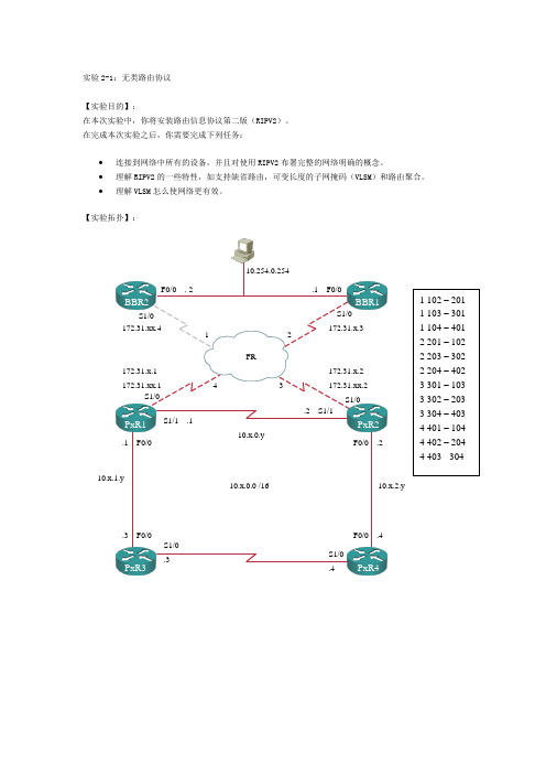
在完成本次实验之后,你需要完成下列任务:• 连接到网络中所有的设备,并且对使用RIPV2布署完整的网络明确的概念。
• 理解RIPV2的一些特性,如支持缺省路由,可变长度的子网掩码(VLSM )和路由聚合。
•理解VLSM 怎么使网络更有效。
【实验拓扑】:BBR2BBR1PxR1PxR2PxR4F0/0 . 2.1 F0/0F0/0 .2.1 F0/0.3 F0/0F0/0 .4S1/0 .3S1/0 .4S1/1 .1.2 S1/110.x.0.y10.x.2.y10.x.1.y10.254.0.254S1/0 S1/0S1/0S1/0172.31.x.1172.31.xx.1172.31.x.2 172.31.xx.2172.31.x.3172.31.xx.4FR12341 102 – 201 1 103 – 301 1 104 – 401 2 201 – 102 2 203 – 302 2 204 – 402 3 301 – 103 3 302 – 203 3 304 – 403 4 401 – 104 4 402 – 204 4 403 - 30410.x.0.0 /16注意:图中x为所在机架编号,y为路由器编号。
【实验帮助】:如果出现任何问题,可以向在值的辅导老师提出并请求提供帮助。
【命令列表】:【任务一】:探索有类路由选择。
使用TELNET或者其他终端程序建立与路由器建立联接。
记住在本实验中x是你的机架编号,y是你的路由器编号。
实验之前,导入初始的路由器配置。
实验过程:第一步:在所有的路由器上配置使用RIP 版本1,并发布网络(10.0.0.0)和,在帧中继边界路由器上,同时发布B类网络172.31.0.0。
第二步:使用命令version 1明确的指定使用RIPv1。
缺省情况下,路由器发送和接收版本1和版本2的路由,设置路由器使用版本1以防止骨干路由器同时运行两种版本。
MyLab辅助功能最佳实践指南说明书

MyLab Accessibility Best Practices GuideStriving to ensure every learner succeeds MyLab course materials Alternative course materials Accessible eTextbooks Alternate format text AccessText Network Braille and large print MyLab accessibility features Turning on Accessibility Platform and navigation Assignments and assessments Question bank for homework and tests Custom Question Builder Microsoft PowerPoint decks Alternate text Videos Discipline-specific media In your MyLab course: New considerations Support and documentation VPATs and other accessibility status documents Table of Contents112222344456789910101010Introduction/OverviewStriving to ensure every learner succeedsMyLab course materialsEmpowering learners will always be central to Pearson’s mission and values. That includes designing instructional content for MyLab® to be fully accessible to students with disabilities while continually improving usability.By honoring the following best practices together, we can enable a wider array of students to thrive through their learning journey — and prepare everyone to prosper.Pearson’s investment in accessible product design and remediation is significant and ongoing as we strive to meet and exceed Web Content Accessibility Guidelines (WCAG 2.1 AA standards) for all our educational materials including those designed for MyLab courses.If for any reason any Pearson eTextbook doesn’t meet a student’s need, Pearson is prepared to provide other course material options. To save everyone time and effort, we’ve partnered with top providers and accessibility experts to expand our capabilities.Alternative course materialsAccessible eTextbooksPearson’s newest eTextbook platform, Pearson+, supports the majority of WCAG 2.1 AA standards and we are continuously updating to improve both accessibility and usability as well as compatibility with assistive technologies. Keep in mind that the most recent edition of each title will provide the most accessible user experience.Pearson+ eTextbooks can be accessed in two ways:1. Using a MyLab courseIf your course uses Pearson MyLab online learning platforms, students may already have access to an accessible eTextbook. To open, go to the MyLab course menu in your browser and select the eTextbook option.2. Logging in to Pearson+ directlyFor classes that do not use MyLab, students can log in to Pearson+ to access eTextbooks from a computer or mobile device (iOS and Android), even when offline.Please email us at ****************************** for title-specific details or if you encounter any issues.Alternate format textIf a Pearson+ eTextbook is not fully accessible for a student based on their needs, an alternate format text can be found within the Pearson VitalSource accessible digital textbooks library.You may purchase Pearson titles as eTextbooks from VitalSource and get instant access to eTextbooks through the VitalSource Bookshelf platform.Learn more about accessible digital eTextbooks from Pearson and get answers to common questions about them.AccessText NetworkPearson partners with the AccessText Network to ensure that students with print-based disabilities that would be better addressed by a non-digital textbook also have that option. Upon request and at no added cost, additional Pearson titles are available for qualified students who buy or rent our print or eTextbook versions through AccessText Network, a clearinghouse for files from all major higher education publishers.A disability services representative must make these title requests from the school who must register with the AccessText Network. The alternative text file will be delivered typically as an untagged PDF (meaning not fully accessible for digital consumption).This method is ideal for:• Schools intending to produce their own braille or large format documents• Students requiring a printed textbook versus digital book as a result of a disability Braille and large printPearson and Allyant, the leading provider of accessible textbook formats in North America, partnered to significantly reduce the turnaround time and cost of providing top-selling Pearson titles in braille and reflowed large print.T-Base can deliver top-selling braille or reflowed large-print textbooks within 10 business days at a substantial cost reduction to institutions. Purchasing accessible textbooks through this new, more efficient process enables educators to focus on helping students succeed in their studies. Explore the ever-expanding Allyant Catalog. Order textbooks in braille or reflowed large print by emailing Allyant at: **************** or calling: 1-800-563-0668.Platform and navigationAll MyLab website pages are screen reader and keyboard-accessible including student pages like Calendar, Homework and Tests, Results, Announcements, and Study Plan.The platform’s interface works with common screen magnifiers. Browser- or device-based contrast settings are respected.*Note: When the student is using keyboard-only navigation or assistive technology within MyLab, the Accessibility Mode is required to complete assignments. (Explore the command-line language students can use to type symbols when Accessibility Mode is turned on.)Assignments and assessments Question bank for homework and testsWhen giving students with disabilities any assignments, be sure their eTextbooks display a copyright year of 2014 or later, and keep in mind that all Pearson business products published in 2016 or later also have accessible eTextbooks.Contact ****************************** for questions about other eTextbooks. Accessible questions are noted with an icon to help instructors select accessible assessmentsand require alternative text.Pearson is actively and consistently increasing the number of accessible questions.Accessible questions and items are:• Screen reader and keyboard accessible• Compatible with common screen magnifiers• Contrast-optimized for vision-impaired access• Created with accessible media such as video with captions and/or video descriptions and images with alternative textCustom Question BuilderWhen editing existing questions or composing your own, remember to:• Add alternative text for images• Use only captioned media• Format fonts for optimal readability• Weigh the use of static vs algorithmic questions for ease of editing and to accommodate student needs• Want to learn more? Watch our MyLab Create Your Own Questions video.• Use questions from other texts and the new enhanced book search. Watch our MyLab Enhanced Book Search video.Microsoft PowerPoint decksMicrosoft PowerPoint decks copyrighted 2018 or later are accessible and include: • Slides that use a clear, simple language and layout• Slides that use accessible fonts of a minimum size• Defined reading order• Accessible color contrast ratios (4.5:1) for text and images of text and color combinations that can be read by students with color blindness• Alternative text descriptions for images• Accessible math, where applicable• Slide titles in the title placeholder for each slide that are unique and concise• Meaningful text or raw URLs to describe hyperlinks• Lists that are built as structured lists• Columns that are created with defined reading order• Tables that are created with PowerPoint’s table feature, are simple grids with predictable rows and columns, and are free of merged cells• Slides that are free of background images and flickering imagesAlternative Text• Alternative text (“Alt Text”) is a written description that conveys visual content of images to students who are blind or have low vision. Pearson eTextbooks with a copyright year of 2018 or later have alternative text for images.• Alternative text is read aloud by screen readers and other assistive technology devices.For complex images, a long description may also be provided via hyperlink to fullydescribe the image.VideosVideos:• Are navigable using screen readers and keyboards• Offer closed captioning in most Business, Reading & Writing, and Math & Statistics products. Note: MIS titles and products released prior to 2010 may vary.• Provide access to certain transcripts via the video player. (See the Further Problem Solving example.) Activate this feature in “Settings.” Some transcripts are available as supplemental materials within the course and do not require a request.• Will include audio descriptions in future releases of visual details on screen that are not apparent from the audio alone.In your MyLab course: New considerations Support and documentationVPATs and other accessibility status documents• Link an HTML eBook directly to its own tab.• Use screen-reader compatible questions. If using Skill Builder, select only the screen reader questions.• Extend testing time by 50% by using the individual student settings.• VPATs and Accessibility Conformance and Remediation Forms (ACC&R) are available for many products upon request and organized and described by feature and status. • To request this information, contact Pearson Disability Support .• Learn more about Pearson’s Accessibility online or contact your Pearson Sales Representative.Discipline-specific mediaMany MyLab products feature discipline-specific media (e.g.: animations, simulations, experiments, flashcards, etc.). For updated details on their accessibility, refer to discipline-specific accessibility status flyers.。
- 1、下载文档前请自行甄别文档内容的完整性,平台不提供额外的编辑、内容补充、找答案等附加服务。
- 2、"仅部分预览"的文档,不可在线预览部分如存在完整性等问题,可反馈申请退款(可完整预览的文档不适用该条件!)。
- 3、如文档侵犯您的权益,请联系客服反馈,我们会尽快为您处理(人工客服工作时间:9:00-18:30)。
Using AccelWare LabUsing AccelWare LabIntroductionThis lab exercise will introduce you to the AccelWare™ DSP IP tool kit generators. AccelWareDSP IP tool kit is a library of over fifty IP generators, available in the form of three tool kits thatproduce synthesizable MATLAB® software for common MATLAB software built-in and toolboxfunctions. Each generator offers macro- and micro-architecture selections that allow fullcustomization of the generated model to the target application requirements. ObjectivesAfter completing this lab, you will be able to:Replace a hand-coded Polyphase Decimation Filter with an equivalent AccelWare DSP IPtool kit modelBuild a simple Digital Down Converter using AccelWare DSP IP tool kit models ProcedurePart A – Replacing the Polyphase Decimation Filter with AccelWare FIRdecimIn this part of the lab, you will replace the polyphase decimation filter that you created in the lastlab with an AccelWare DSP IP tool kit FIRdecim model.n Copy the project files developed in the lab MultirateDesign/part_b (for the polyphase decimation by 2 filter) into the folder UsingAccelWare/part_a? 1.What is the cutoff of the non-decimated filter?________________________________________________________________________________________________________________________________ o Create a new function called “ddc.m” with the same inputs and outputs as the decimation filter. Call this function from the streaming loop. Call the decimation filter created in theMultirate Design lab from this new function. Basically, you are pushing the decimation filterdown a level of hierarchy onto a new function. Doing this will allow you to add additionalfunctionality to the ddc.m function in Part B of this lab. Once complete, simulate the model; itshould simulate the samefor n = 1:length(X)[y(n),valid(n)] = ddc(X(n));endp Invoke the AccelDSP™ synthesis tool and click the Project icon on the toolbar. Select the Create AccelWare Core tab, and then select the FIRDecim IP block as shown belowq Enter/Select the following parameters:ParameterValue Filter Coefficients Sourcefrom text file Coefficient fileSelect the “b.txt” file created in the script file b = fir1(NUMTAPS-1,BE); save b.txt –ascii –double b; m (2:65000)2Filter formDirect – Resource Shared Branches auto Programmable Coefficientsno Storage MappingRegister Mapped Number of Channels1 Input StructureSerial Pipeliningno Input word length16 Input fractional length13 Coefficients word length16 Output bitwidthauto Truncation8 Destination folder current project folderr Set the Project Options as follows:OptionValue Frequency (MHz) 100 RTL Simulation ModelsimOnce the AccelWare DSP IP tool kit decimation filter has been generated, a project including a testbench is also created. Perform the floating-point simulation step and look at thegenerated plot. The bottom plot is a comparison of the AccelWare DSP IP tool kit decimation filter response against a MATLAB software behavioral model. The AccelWare DSP IP tool kit model is fixed-point and you can see that the error is on the order of 10e-5. When you replace the synth_filter_decim2 filter with this one, you should expect the max error plot to show a similar max error.s Run the flow through Verify Fixed Point, and then save and close the firdecim projectt When you generated the IP, a new folder was created in the part_a folder called “firdecim_001”. Copy the “firdecim_001.m” and the “firdecim_001.add” files from this folder and place them into the 05_UsingAccelWare/part_a folderNote: The file “firdecim_001.m” is a synthesizable MATLAB software file that will be used in place of the hand-coded decimation filter. The “firdecim_001.add” file is a hierarchical directives file that contains information used by the AccelDSP synthesis tool to generate the RTL model.Note: The hardware architecture used to implement the AccelWare DSP IP tool kit decimation filter has one additional clock cycle of latency than the decimation filter created in the previous lab.In the following steps, you are going to use a text editor to substitute the AccelWare DSP IP tool kit firdecim_001(x) filter for the synth_filter_decin2(x) and then implement the filter using the AccelDSP synthesis tool.n Open the ddc.m file for edit and substitute the AccelWare DSP IP tool kit firdecim_001(x) filter for the synth_filter_decin2(x). The code should look like the following:function [FilterOut,valid] = ddc(FilterIn);%[FilterOut,valid] = synth_filter_decim2(FilterIn);[FilterOut,valid] = firdecim_001(FilterIn);o Use MATLAB software to simulate the AccelWare DSP IP tool kit decimation filter. As shown below, the filter response should be the samep Invoke the AccelDSP synthesis tool. Create a new project and call the project “proj2” and perform the Verify Floating Point, Analyze, Generate Fixed Point, and Verify Fixed Point stepsq Perform the Generate RTL step and record the number of hardware resources from the Generate RTL Report:# of Multipliers# of Adders# of Subtractorsr Perform the Verify RTL step and record the following values from the Verify RTL Report: Startup Clock CyclesCycles per Outputs Perform the Synthesize RTL step and record the following values from the Xilinx XST Synthesis Report:SlicesSlice Flip-Flops4 input LUTsbonded IOBsFIFO16/RAMB16sGCLKsDSP48sEstimated FrequencyInput SamplingPart B – Creating a Simple Digital Down ConverterYou are going to implement a simplified version of the typical digital down converter (shownbelow) by using two decimation filters. DDCs are typically used to perform channel accessfunctions in digital receivers. DDCs accept an input signal sampled at a high rate and downconverts it to a band-of-interest. Often a CIC decimation filter is used to perform a largedownsampling operation followed by two polyphase decimation filters.In this part of the lab, you are going to connect two polyphase decimation filters in series to createa simple down sampler with a total decimation of 4.n Copy the files from the UsingAccelWare/part_a folder into the UsingAccelWare/part_b folder and change the MATLAB software working directory to the UsingAccelWare/part_bfoldero Copy the files “firdecim_001.m” and “firdecim_001.add” to create a second file pair “firdecim_002.m” and “firdecim_002.add”. Because the M-file uses MATLAB softwarepersistent variables, you cannot simply instantiate the same file twice—you need to create aunique file name for each instantiationp Edit the “ddc.m” file to connect the two polyphase decimation filters in series to realize a total downsample of 4. Use the valid signals from each function to control this operation. Thesecond decimation filter should only be called when the valid signal from the first decimationfilter is active-High. Example code is shown below:[y1,valid1] = firdecim_001(x_sum);if valid1 == 1[y,valid] = firdecim_002(y1);elsey = 0;valid = 0;endNote: In the next section of the lab, you are going to complete the simple digital down converter by adding a direct digital frequency synthesis function to the down sampler. The DDS consists of a phase accumulator block feeding a sin function. A standard function call to the MATLAB software sin() will be used but the AccelDSP synthesis tool kit will use IP Explorer to automatically select and generate a specific hardware architecture for the sin function.PhaseInq To support the functionality of a DDS, add a new input to the design function “ddc” called “PhaseIn” as shown below:for n = 1:length(X)[y(n),valid(n)] = ddc(X(n),PhaseIn);endr In the top-level script file, define the input “PhaseIn” as shown below:% Set the Phase In to 14 MHz for the DDS, assuming L = 20 bitsDDS_Frequency = 100;% MHzDesiredFreq = 14; % MHzPhaseIn = floor(DesiredFreq/DDS_Frequency*2^20);s In the design function “ddc.m”, add the following code at the top of the file to model the DDS function. The output of the DDS function is “Sine”. Note the use of the standard function“sin()”% Create Direct Digital Synthesizerpersistent phase_accumif isempty(phase_accum)phase_accum = 0;end% The scaling for theta and phase_accum is related to% the word-length of L (20 bits)theta = floor(phase_accum/2^11)*pi/2^8;phase_accum = phase_accum + PhaseIn;Sine = sin(theta);t Add the variable “Sine” to the design function output argument list. You want to plot the sine wave values over time from the script fileu Modify the MATLAB software language in the “ddc” function to multiply the output of the sine wave generator “Sine” with the DDC function input “x”. This is shown belowsymbolically as the multiply operation:v Modify the output analysis in the script file, as shown below, because you want to show the effects of the DDC in a meaningful way% Generate power spectral density of the filter outputs[Pout,Wout]=aw_psd(y,256,100e6);[Pout2,Wout2]=aw_psd(Sine,1024,100e6);% Plot the PSD Responsesubplot(2,1,1);plot(Wout,10*log10(Pout),'r');title('DDC PSDResponse')In the following steps you are going to implement the filter using the AccelDSP synthesis tool. n Simulate the algorithm to ensure that there are no coding errors. The following waveform should appear:o Load the project for this design into the AccelDSP synthesis tool and perform the Verify Floating Point, Analyze, and Generate Fixed Point stepsp Expand the project browser, select the instantiation of the sin function, and view the propertiesq Expand down into the sin function and double-click any of the objects. This will allow you to view the MATLAB software source code for the sin function. The AccelDSP synthesis toolhas automatically generated a sin function and swapped it into the design. The architecturethat was selected was CORDIC. This is based in the input bit widthsr Set a quantize directive on the variable “theta” and set it to a word length = 20, fractional width = 15s Perform the Generate Fixed Point step again? 2.Which hardware macro-architecture did IP Explorer select for the sin function?________________________________________________________________________________________________________________________________ ConclusionAccelWare DSP IP tool kit modules can be auto-inferred or manually generated. Each moduleprovides multiple silicon architectures that you can customize. By default, IP Explorer selects anappropriate architecture for an AccelWare DSP IP tool kit instance; however, the designer canoverride the default selection.。