2006-Enhancement-Mode MISHFETs
SPE参考文献:著录存在的问题与规范化表达
综合理论课程教育研究学法教法研究 277计部门要加强对被审计单位或部门的监督,也可考虑和高校联合起来,共同开展回头看,等等。
通过采取一系列务实、创新的举措,真正将整改工作落到实处。
2.提高质量。
无论是审计工作方式还是撰写审计报告,都要精益求精,经得住推敲。
如果不认真对待审计内容,工作拖拖拉拉、质量不高的话,那么审计出来的结果也是经不起推敲,不能加以运用的。
这样浪费了大量的人力、物力、财力资源,却没有收到实效。
所以,要全方面提高审计工作的质量。
一是端正审计工作的态度,要以高度负责的精神和态度来对待审计,不可马马虎虎地工作。
二是优化审计工作流程,创新审计工作方式。
工作要有逻辑性,按照要求按部就班、不折不扣地做好工作,做到流程清楚,逐项落实;要改变传统的工作方式,按照审计的要求创新工作思路和工作方法,力求将各项工作做得扎实、务实。
三是要撰写高质量的审计工作报告。
审计工作报告是对本次审计工作的总结,具有很强的针对性和指导性,审计工作报告质量的好坏,直接影响了本次审计是否取得成功,这对审计人员提出了更高的要求。
一方面审计人员要懂业务,会正确使用审计术语,了解并掌握审计工作的整个流程,另一方面要有较强的综合分析能力和文字综合能力,能够透过现象看本质,将审计内容进行高度概括和凝练,从而提升审计报告的质量。
3.加强运用。
要将审计后的结果加以应用,防止出现“只审不用”的现象。
被审计单位班子成员要正确认识审计出的问题,对这些问题高度重视,进行积极的整改。
另外,审计者也要加强对审计结果的运用,尤其在审计工作流程结束后,仍然要重视审计结果的运用,还要将运用情况上报给审计部门,这也是对本次审计工作的重视及肯定。
三、结语高校领导干部的经济责任审计对高校经济活动的正常开展具有非常重要的作用。
随着高校的发展,一些新情况新问题也会出现,对经济责任审计将会提出新的更高的要求。
高校领导干部的经济责任审计要紧密结合工作实际,工作者要牢固树立创新意识,不断对审计工作方式进行创新,优化工作流程,提升工作质量,切实取得经济责任审计工作的实效。
尺度适应性二代小波的图像去噪方法

由于传 统小 波存 在 上 述 缺 点 , 第二 代 提 升 小 波 产生 , 所有 的传 统 小 波 都 可 以 由提 升方 法 中的 基 本提 升和 对偶 提 升分 解 而 成 , 升 方法 能 够 包 提
e f in n i g e n ii g fi e ti ma e d - o sn . c
Ke r s s c n e e a in wa e e ; en iig ; c l- d p ie d c mp sto l o i m ; i r v d y wo d : e o d g n r t v l t d - o sn o s ae a a t e o o i n ag rt v i h mp o e t rs od v le h e h l a 1 J
提 出的多分 辨 分 析 ( A) 波 理 论 _为 图像 去 MR 小 1 j
噪提供 了更理 想 的工 具 。一般 可 以将 传统 的小 波 去 噪 的方 法分 为 三 大类 [ 第 一类 方 法 是 基 于 小 : 波 变换模 极大值 原理 的方 法 , 此方 法 在 去 噪 过 程
容 传统所 有 的小波 。
中 图 分 类 号 : 7. U6 2 7 文献标志码 : A
I a e—o sn e h d b s d o he s a e a a i e m ge d — ii g m t o a e n t c l— d ptv n —
sc e ond ge r t on w a l t ne a i ve e
image alignment and stitching a tutorial
Richard Szeliski Last updated, December 10, 2006 Technical Report MSR-TR-2004-92
This tutorial reviews image alignment and image stitching algorithms. Image alignment algorithms can discover the correspondence relationships among images with varying degrees of overlap. They are ideally suited for applications such as video stabilization, summarization, and the creation of panoramic mosaics. Image stitching algorithms take the alignment estimates produced by such registration algorithms and blend the images in a seamless manner, taking care to deal with potential problems such as blurring or ghosting caused by parallax and scene movement as well as varying image exposures. This tutorial reviews the basic motion models underlying alignment and stitching algorithms, describes effective direct (pixel-based) and feature-based alignment algorithms, and describes blending algorithms used to produce seamless mosaics. It closes with a discussion of open research problems in the area.
FME 使用手册

简介(注意并非针对本文,可能有差异) 改为二维圆弧,圆弧的形状由参数控制,例 如常数或属性值 改为二维矩形,矩形的最大最小坐标为指定 的常数或原始要素的属性值 根据参数创建二维要素,并输入转换流程 改为二维椭圆,椭圆的形状由参数控制 改为二维要素(删除Z坐标) 按格网方式生成一批二维点状要素,须指定 原点和间距 将输入的一批要素改为按格网方式生成的二 维点状要素,格网的范围(至少)覆盖全部 输入要素的外接矩形,格网间距须指定 给要素增加一个二维的节点(最后一个节 点),其坐标由原始要素的属性获得 改为二维的点,其坐标由原始要素的属性获 得 改为二维圆弧(注:原文如此),圆弧的形 状由参数控制,例如常数或属性值 根据参数创建三维要素,并输入转换流程 改为三维要素,Z坐标由指定的属性或常数 获得 三维插值:沿着一个线状要素、根据起始值 和结束值内插高程 给要素增加一个三维的节点(最后一个节 点),其坐标由原始要素的属性获得 改为三维的点,其坐标由原始要素的属性获 得 坐标仿射变换 仿射纠正,用于纠正一批要素使之最接近参 考要素 聚合过滤:根据图形是否为聚合类型而分别 输出
简介注意并非针对本文可能有差异2darcreplacer改为二维圆弧圆弧的形状由参数控制例如常数或属性值2dboxreplacer改为二维矩形矩形的最大最小坐标为指定的常数或原始要素的属性值2dcreator根据参数创建二维要素并输入转换流程2dellipsereplacer改为二维椭圆椭圆的形状由参数控制2dforcer改为二维要素删除z坐标2dgridcreator按格网方式生成一批二维点状要素须指定原点和间距将输入的一批要素改为按格网方式生成的二维点状要素格网的范围至少覆盖全部输入要素的外接矩形格网间距须指定给要素增加一个二维的ห้องสมุดไป่ตู้点最后一个节点其坐标由原始要素的属性获得改为二维的点其坐标由原始要素的属性获得2dgridreplacer2dpointadder2dpointreplacer3darcreplacer改为二维圆弧注
基于UDCT系数的改进HMT和在图像去噪中应用

基于UDCT系数的改进HMT和在图像去噪中应用杨兴明;陈海燕;王刚;王彬彬;赵银平【摘要】通过对均匀离散曲波变换(Uniform Discrete Curvelet Transform,UDCT)系数的统计特性研究,同时对系数相关性度量指标互信息量的分析,最终选择隐马尔可夫树模型对其系数建模,且用EM算法训练序列;针对训练时间过长问题,通过分析系数的衰减性和尺度间系数延续性,提出一种新的对算法参数初值的方差和状态转移矩阵的优化方法,实验结果证明,在采用峰值信噪比和相似度作为图像去噪效果的度量时,同等条件下文中提出的算法比Wavelet HMT、Contourlet HMT、UDCT HMT算法有较好的实时性和去噪效果。
%Based on the statistical properties of coefficients of the Uniform Discrete Curvelet Transform(UDCT), and the analysis of correlation metric mutual information about the coefficients, this paper chooses the Hidden Markov Tree to model the coefficients finally and trains the sequence with the EM algorithm. With amount of time consuming, an optimization EM algorithm based on HMT of UDCT coefficients is presented; it further optimizes the algorithm by defining the variance and state transition matrix based on the attenuation of coefficients and continuity between the scales. Experimental results show that, in the use of similarity and Peak Signal to Noise Ratio effect as the measurement of image de-noising, under the same conditions, the algorithm proposed has better real-time and de-noising effect than the Wavelet HMT, Contourlet HMT, UDCT HMT algorithm.【期刊名称】《计算机工程与应用》【年(卷),期】2013(000)018【总页数】6页(P195-199,231)【关键词】均匀离散曲波变换;互信息;隐马尔可夫树模型(HMT);最大期望(EM)算法;图像去噪【作者】杨兴明;陈海燕;王刚;王彬彬;赵银平【作者单位】合肥工业大学计算机与信息学院,合肥,230009;合肥工业大学计算机与信息学院,合肥,230009;合肥工业大学计算机与信息学院,合肥,230009;合肥工业大学计算机与信息学院,合肥,230009;合肥工业大学电气与自动化工程学院,合肥,230009【正文语种】中文【中图分类】TP751.1图像处理的应用非常广泛,例如去噪、融合、分割等[1-2],图像噪声去除的基本方法有空间域的和变换域的,空间域滤波能够有效滤除光滑区域的噪声但容易模糊边缘;变换域去噪的方法主要由傅里叶变换和小波变换,而小波变换由于其多分辨率和时频局部等特性,广泛用于图像去噪。
利用重要性采样提高深度学习模型的学习效率

利用重要性采样提高深度学习模型的学习效率深度学习在计算机科学和人工智能领域中取得了巨大的成功。
然而,深度学习模型的训练往往需要大量的时间和计算资源,尤其是当处理大规模数据集时,会面临训练过程变慢的问题。
重要性采样(importance sampling)是一种常用的方法,可用于提高深度学习模型的学习效率。
本文将探讨重要性采样的原理和在深度学习中的应用。
重要性采样是一种用于减少采样偏差并提高采样效率的技术。
在深度学习中,模型的训练通常基于大量的采样数据集。
然而,某些样本的重要性可能高于其他样本,它们对模型的训练结果更具影响力。
因此,传统的随机采样方法可能会在采样过程中忽略掉一些重要的样本,从而导致训练效率低下。
重要性采样通过为各个样本赋予不同的采样权重,提高了对重要样本的采样概率,从而更有效地探索样本空间。
在深度学习中,重要性采样的应用可以通过两种主要方式来实现:重要性采样训练和重要性采样调整。
首先,重要性采样训练是一种基于重要性采样的模型训练方法。
它通过调整样本的权重来降低对低重要性样本的关注,同时增加对高重要性样本的关注。
这样一来,模型将更有可能学习到那些具有更大贡献的样本特征,从而提高模型的学习效率。
重要性采样训练可以应用于深度学习中的各个阶段,包括数据预处理、模型训练和优化等。
其次,重要性采样调整是一种基于重要性采样的模型参数更新方法。
在传统的梯度下降算法中,每个样本的梯度都被视为具有相同的重要性。
而重要性采样调整方法则根据每个样本的采样权重,调整对应的梯度,使得对于更重要的样本,其梯度对模型参数的更新更有贡献。
通过这种方式,模型能够更有效地更新参数,从而加快模型的收敛速度,提高学习效率。
此外,重要性采样还可以与其他技术相结合,以进一步提高深度学习模型的学习效率。
例如,与自适应采样方法结合使用,可以根据每个样本的重要性动态调整采样概率,从而更好地平衡采样效率和样本质量。
另外,与优化方法相结合,例如基于梯度的优化方法,可以更好地利用重要性采样的信息,加速模型的学习过程。
中等植被覆盖区金矿蚀变TM及JERS_1OPS遥感信息增强技术

中等植被覆盖区金矿蚀变T M 及JERS-1OPS 遥感信息增强技术张 满 郎(中国科学院遥感应用研究所,北京 100101)摘 要 本文分析了与金矿化相伴的蚀变矿物(铁氧化物、粘土矿物、碳酸盐矿物)的反射光谱吸收特征及金矿区上覆植被反射光谱对金矿化蚀变信息的干扰,同时介绍了利用植被指数法、比值 主成份变换法和植被掩模法对陆地卫星T M 、JERS-1OPS 等遥感图像进行处理,压抑植被反射光谱干扰信息和增强金矿化蚀变反射光谱信息的方法和效果。
关键词 图像处理 植被 金矿蚀变 信息增强1 前言研究区位于河北省东部,为一中等植被覆盖区,构造上位于华北地台北缘。
区内主要金矿类型为太古界绿岩带型金矿、燕山期花岗岩内外接触带细脉浸染型金矿及矽卡岩型金矿。
与金矿化相伴的热液蚀变有硅化、高岭石化、碳酸盐化、绿泥石化、黄铁矿化以及表生褐铁矿化。
采用的遥感数据为1987年5月14日获取的陆地卫星TM 数据和1992年6月10日获取的日本地球资源卫星光学扫描仪(JERS-1OPS)数据。
通过对与金矿化相伴的蚀变岩石、矿物及植被反射光谱吸收特征的分析,采用植被指数、比值 主成份变换以及植被掩模等方法进行图像处理,以便在增强蚀变信息的同时尽可能地排除植被干扰。
2 蚀变矿物的光谱吸收特征对岩金矿床而言,金的富集成矿均与含金热液活动有关,因此金矿化围岩常常发育热液蚀变,而且在遥感图像上也必然含有丰富的金矿化和热液蚀变信息。
因此,放在我们面前的主要任务就是通过遥感图像处理技术来提取与金矿化共生的热液蚀变矿物、构造蚀变岩及其风化产物等信息。
其中粘土类蚀变矿物(如高岭石、绢云母、伊利石、蒙脱石、白云母等)反射光谱在2.17 m-2.21 m 处存在显著的光谱吸收带,碳酸盐矿物(如方解石、白云石、菱镁矿、菱铁矿等)的反射光谱在2.30 m- 2.35 m 处存在特征光谱吸收带,而铁的氧化物、氢氧化物(如针铁矿、赤铁矿、黄钾铁矾等组成的铁的氧化物、氢氧化物),其反射光谱在0.45 m,0.86 m 波长处具有特征光谱吸收带。
686 RAPID COMMUNICATION nnnnnnnnnnnnnnnnnnnnnnnnnnnnnnnnnnnnnnnnnnnnnnnnnnnnnnnnnnnnnnnnn n
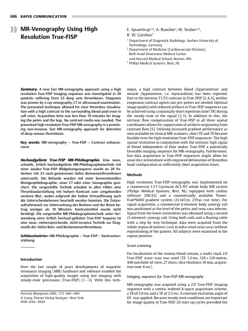
important additional findings like common iliac vein or inferior vena cava thrombosis (Fig.4).In two further cases,unknown contralateral thrombosis was seen with True-FISP MR-venog-Fig.1True-FISP MR-venography (TR 5.0ms,TE 2.5ms,860 860 m in-plane resolution)in a 42year old patient without thrombosis.Veins and arteries are displayed with a bright signal.A black rim surrounding the vessel lumen is readily apparent (magnification).True-FISP sequence for MR-venography,which may allow for a high-contrast MR-venography without costly contrast agent.Technical considerations of MR-venography using high resolution True-FISPTrue-FISP sequences demonstrate a T1/T2contrast due to data acquisition in a steady state condition of the transverse magnetization [9].Therefore,the long T2of blood allows for Fig.2True-FISP MR-venography (TR 5.0ms,TE 2.5ms,860 860 m in-plane resolution)in a 31year old pregnant plete left femoral (a )and iliac (b )vein thrombosis is diagnosed because of the dark signal,whereas open superficial and deep right veins show a bright signal.The inferior vena cava is highly compressed due to pregnancy (arrow in c ).in the inferior vena cava(Fig.4),a highly important finding for therapy.In two other patients,tumor masses causing venous compression were diagnosed on the MR-images.This shows the Recently,new MR-approaches for fast detection ofwith fast MR-venography。
- 1、下载文档前请自行甄别文档内容的完整性,平台不提供额外的编辑、内容补充、找答案等附加服务。
- 2、"仅部分预览"的文档,不可在线预览部分如存在完整性等问题,可反馈申请退款(可完整预览的文档不适用该条件!)。
- 3、如文档侵犯您的权益,请联系客服反馈,我们会尽快为您处理(人工客服工作时间:9:00-18:30)。
Enhancement-Mode Si3N4/AlGaN/GaN MISHFETs Ruonan Wang,Yong Cai,Chi-Wai Tang,Kei May Lau,Fellow,IEEE,and Kevin J.Chen,Member,IEEEAbstract—Enhancement-mode Si3N4/AlGaN/GaN metal–insulator–semiconductor HFETs(MISHFETs)with a1-µm gate footprint are demonstrated by combining CF4plasma treatment technique and a two-step Si3N4deposition process.The threshold voltage has been shifted from−4[for depletion-mode HFET] to2V using the techniques.A15-nm Si3N4layer is inserted under the metal gate to provide additional isolation between the gate Schottky contact and AlGaN surface,which can lead to reduced gate leakage current and higher gate turn-on voltage.The two-step Si3N4deposition process is developed to reduce the gate coupling capacitances in the source and drain access region,while assuring the plasma-treated gate region being fully covered by the gate electrode.The forward turn-on gate bias of the MISHFETs is as large as7V,at which a maximum current density of 420mA/mm is obtained.The small-signal RF measurements show that the current gain cutoff frequency(f T)and power gain cutoff frequency(f max)are13.3and23.3GHz,respectively.Index Terms—AlGaN/GaN,enhancement-mode(E-mode) MISHFET,fluoride-based plasma treatment,Si3N4.I.I NTRODUCTIONO WING to the high power handling capacity and excel-lent capability of operating at high temperatures,wide bandgap AlGaN/GaN heterostructurefield effect transistors (HFETs)are attracting interest for applications in RF power amplifiers and high-temperature digital integrated circuits[1]–[7].From the application point of view,enhancement-mode (E-mode)AlGaN/GaN HFETs have many advantages over depletion-mode(D-mode)HFETs.With the E-mode HFETs, the negative-polarity voltage supply can be eliminated,leading to reduced circuit complexity and reduced cost.As for the monolithic integration of E-mode and D-mode HFETs also en-ables the implementation of direct-coupled FET logic(DCFL) that features the simplest circuit configuration for HFET-based logic circuits.Many works about E-mode HFETs and E/D-mode integration have been undertaken by using recess gate [8],fluoride-ride plasma treatment techniques[4],[9],[10],and platinum-based gate electrode[11].At the same time,E-mode metal-insulator-semiconductor HFETs(MISHFETs)are still lacking.The MISHFETs[12]–[15],when E-mode operation is made possible,can provide several benefits in applications. First,MISHFETs are preferred for high-temperature operation, because the additional insulator between the gate electrode and III-nitride semiconductor provides an additional potential barrier between the gate electrode and the channel,whichManuscript received May11,2006;revised July7,2006.This work was supported by the Hong Kong RGC Competitive Earmarked Research Grant 611706.The review of this letter was arranged by T.Mizutani.The authors are with the Department of Electronic and Computer Engineer-ing,Hong Kong University of Science and Technology,Kowloon,Hong Kong (e-mail:reynold@ust.hk;eekjchen@ust.hk).Digital Object Identifier10.1109/LED.2006.882522then suppresses the thermionic emission and tunneling at high temperature and keep the gate voltage swing reasonably large for proper circuit operation.Second,the increased gate turn-on voltage can facilitate the accommodation of a more positive threshold voltage,which is preferred not only for assuring the complete turn-off of the device at zero bias,but also for providing improved device safety for certain circuits such as power switches.In this letter,we report thefirst E-mode Si3N4/AlGaN/GaN MISHFETs with a two-step Si3N4process which features a thin layer of Si3N4(15nm)under the gate and a thick layer of Si3N4(∼125nm)in the access region. Thefluoride-based plasma treatment technique[4],[9]was adopted to convert the device from D-mode to E-mode.The E-mode MISHFETs with1-µm long gate footprint exhibit a threshold voltage of2V,a forward turn-on gate bias of6.8V (compared to∼3V realized in E-mode AlGaN/GaN HEMTs) and a maximum current density of420mA/mm.II.D EVICE S TRUCTURE AND F ABRICATIONThe AlGaN/GaN HFET structure used in this letter is grown on(0001)sapphire substrates in an Aixtron AIX2000HT metal-organic chemical vapor deposition(MOCVD)system. The HFET structure consists of a∼50-nm thick low temper-ature GaN nucleation layer,a2.5-µm thick unintentionally doped GaN buffer layer,and an AlGaN barrier layer with nominal30%Al composition.The barrier layer is composed of a3-nm undoped spacer,a16-nm carrier supplier layer doped at2×1018cm−3,and a2-nm undoped cap layer.The capacitance–voltage(C−V)measurement by mercury probe yields an initial threshold voltage of−4V for this sample. The processflow is illustrated in Fig.1.Atfirst,device mesa is formed using Cl2/He plasma dry etching in an STS inductively coupled plasma reactive ion etching(ICP-RIE)sys-tem followed by the source/drain ohmic contact formation with Ti/Al/Ni/Au(20nm/150nm/50nm/80nm)annealed at850◦C for30s,as shown in Fig.1(a).Then,thefirst Si3N4layer (∼125nm)is deposited on the sample by plasma enhanced chemical vapor deposition(PECVD)[Fig.1(b)].After gate windows with1-µm length are opened by photolithography,the sample was put in an RIE system under CF4plasma treatment, which accomplished two goals:removal of the Si3N4and incorporation offluorine ions in the AlGaN[4],[9].The RF power of the plasma is150W,as shown in Fig.1(c).The gasflow is controlled to be150sccm,and the total etching and treatment time is190s.The incorporation offluorine ions fulfills the task of converting the treated region from D-mode to E-mode HFET[9].After removing the photoresist,the second Si3N4film(∼15nm)is deposited by PECVD to form the insulating layer between gate metal and AlGaN[Fig.1(d)].0741-3106/$20.00©2006IEEEFig. 1.Schematics showing the processflow of E-mode MISHFETs: (a)Active region and ohmic contact.(b)Thefirst Si3N4layer deposition.(c)Gate area definition and plasma treatment.(d)The second Si3N4layer deposition.(e)Si3N4patterned.(f)Schottky contact and interconnection. Subsequently,the Si3N4layer is patterned and etched to open windows in the source and drain ohmic contact regions,as shown in Fig.1(e).Next,the2-µm long gate electrodes are defined by photolithography followed by e-beam evaporation of Ni/Au(∼50nm/300nm)and liftoff[Fig.1(f)].To make sure the gate electrode covers the entire plasma-treated region,the metal gate length(2µm)is chosen to be larger than the treated gate area(1µm),leading to a T-gate configuration.The gate overhang in the source/drain access regions is insulated from the AlGaN layer by the thick Si3N4layer,keeping the gate capacitances at low level.At last,the whole sample is annealed at400◦C for10min to repair the plasma-induced damage in the AlGaN barrier and channel[4],[9].Measured from the foot of gate,the gate–source and gate–drain spacings are both 1.5µm.The E-mode MISHFETs are designed with gate width of10µm for dc testing and100µm for RF characterizations.III.D EVICE C HARACTERISTICSThe dc output characteristics of the E-mode MISHFETs are plotted in Fig.2.The devices exhibit a peak current density of∼420mA/mm,an ON-resistance of∼5.67Ω·mm and a knee voltage of∼3.3V at V GS=7V.Fig.3(a)shows the transfer characteristics of the same device with1×10-µm gate dimension.It can be seen that the threshold voltage V th is about 2V,indicating a6-V shift of V th(compared to a conventional D-mode HFET)achieved by the insertion of the Si3N4insu-lator and plasma treatment.The peak transconductance g m is ∼125mS/mm.Fig.3(b)shows the gate leakage current at both the negative bias and forward bias.The forward biasturn-on Fig.2.DC output characteristics of E-modeMISHFETs.Fig.3.(a)Transfer characteristics and(b)gate leakage current of E-mode MISHFETs.voltage for the gate is∼6.8V,providing a much larger gate bias swing compared to the E-mode HFETs[9].Pulse measurements were taken on the E-mode MISHFETs with1×100-µm gate dimensions with a pulse length of 0.2µS and a pulse separation of1mS.The quiescent bias point is chosen at V GS=0V(below V th)and V DS=20V.Fig.4 shows that the pulsed peak current is higher than the static one,indicating no current collapse in the device.The static maximum current density of the large device with a100-µm gate width is∼330mA/mm,smaller than the device with 10-µm gate width(∼420mA/mm).The lower peak current density in the larger device is due to the self-heating effect that lowers the current density.Since little self-heating occurs dur-ing pulse measurements,the maximum current for the100-µm wide device can reach the same level as the10-µm wide device. On wafer small-signal RF characteristics were performed from 0.1to39.1GHz on the100-µm wide E-mode MISHFETs at V DS=10V.As shown in Fig.5,the maximum current gain cutoff frequency(f T)and power gain cutoff frequency(f max)W ANG et al.:ENHANCEMENT-MODE Si 3N 4/AlGaN/GaN MISHFETs795Fig.4.Pulse measurements of E-modeMISHFETs.Fig.5.Small-signal RF characteristics of E-mode MISHFETs.are 13.3and 23.3GHz,respectively.When the gate bias is 7V ,the small-signal RF performance does not degrade much,with an f T of 13.1GHz and an f max of 20.7GHz,indicating that the Si 3N 4insulator offers an excellent insulation between gate metal and semiconductor.IV .C ONCLUSIONThe fabrication technology for E-mode AlGaN/GaN MISH-FET has been developed.The CF 4plasma treatment is used to convert D-mode devices to E-mode,shifting the threshold voltage from negative to positive.A two-step Si 3N 4deposition process is used to insert a thin layer of Si 3N 4as the gate insulating layer and create a thick layer between the gate electrode and the access region.The gate bias of the E-mode MISHFETs can be applied up to 7V .The E-mode MISHFETsshow no current collapse under pulse operation,and good dc and RF performances are obtained.R EFERENCES[1]V .Kumar,W.Lu,R.Schwindt,A.Kuliev,G.Simin,J.Yang,M.A.Khan,and I.Adesida,“AlGaN/GaN HEMTs on SiC with f T of over 120GHz,”IEEE Electron Device Lett.,vol.23,no.8,pp.455–457,Aug.2002.[2]Y .F.Wu,A.Saxler,M.Moore,R.P.Smith,S.Sheppard,P.M.Chavarkar,T.Wisleder,U.K.Mishra,and P.Parikh,“30-W/mm GaN HEMTs by field plate optimization,”IEEE Electron Device Lett.,vol.25,no.3,pp.117–119,Mar.2004.[3]J.W.Johnson,E.L.Piner,A.Vescan,R.Therrien,P.Rajagopal,J.C.Roberts,J.D.Brown,S.Singhal,and K.J.Linthicum,“12W/mm AlGaN-GaN HFETs on silicon substrates,”IEEE Electron Device Lett.,vol.25,no.7,pp.459–461,Jul.2004.[4]Y .Cai,Z.Q.Cheng,W.C.W.Tang,K.J.Chen,and u,“Mono-lithic integration of enhancement-and depletion-mode AlGaN/GaN HEMTs for GaN digital integrated circuits,”in IEDM Tech.Dig.,Dec.2005,pp.771–774.[5]I.Daumiller,C.Kirchner,M.Kamp,K.J.Ebeling,and E.Kohn,“Evalu-ation of the temperature stability of AlGaN/GaN heterostructure FET’s,”IEEE Electron Device Lett.,vol.20,no.9,pp.448–450,Sep.1999.[6]P.G.Neudeck,R.S.Okojie,and C.Liang-Yu,“High-temperatureelectronics—A role for wide bandgap semiconductors?,”Proc.IEEE ,vol.90,no.6,pp.1065–1076,Jun.2002.[7]T.Egawa,G.Y .Zhao,H.Ishikawa,M.Umeno,and T.Jimbo,“Character-izations of recessed gate AlGaN/GaN HEMTs on sapphire,”IEEE Trans.Electron Devices ,vol.48,no.3,pp.603–608,Mar.2003.[8]M.Micovic,T.Tsen,M.Hu,P.Hashimoto,P.J.Willadsen,osavljevic,A.Schmitz,M.Antcliffe,D.Zhender,J.S.Moon,W.S.Wong,and D.Chow,“GaN enhancement/depletion-mode FET logic for mixed signal applications,”Electron.Lett.,vol.41,no.19,pp.1081–1083,Sep.2005.[9]Y .Cai,Y .G.Zhou,K.J.Chen,and u,“High-performanceenhancement-mode AlGaN/GaN HEMTs using fluoride-based plasma treatment,”IEEE Electron Device Lett.,vol.26,no.7,pp.435–437,Jul.2005.[10]T.Palacios,C.-S.Suh,A.Chakraborty,S.Keller,S.P.DenBaars,andU.K.Mishra,“High-performance E-mode AlGaN/GaN HEMTs,”IEEE Electron Device Lett.,vol.27,no.6,pp.428–430,Jun.2006.[11]A.Endoh,Y .Yamashita,K.Ikeda,M.Higashiwaki,K.Hikosaka,T.Matsui,S.Hiyamizu,and T.Mimura,“Non-recessed-gate enhancement-mode AlGaN/GaN high electron mobility transistors with high RF performance,”Jpn.J.Appl.Phys.,vol.43,no.4B,pp.2255–2258,2004.[12]M.A.Khan,X.Hu,G.Sumin,A.Lunev,J.Yang,R.Gaska,and M.S.Shur,“AlGaN/GaN metal oxide semiconductor heterostructure field effect transistor,”IEEE Electron Device Lett.,vol.21,no.2,pp.63–65,Feb.2000.[13]X.Hu,A.Koudymov,G.Simin,J.Yang,and M.A.Khan,“Si 3N 4/AlGaN/GaN-metal-insulator-semiconductor heterostructure field-effect transistors,”Appl.Phys.Lett.,vol.79,no.17,pp.2832–2834,Oct.2001.[14]A.Chini,J.Wittich,S.Heikman,S.Keller,S.P.DenBaars,and U.K.Mishra,“Power and linearity characteristics of GaN MISFET on sap-phire substrate,”IEEE Electron Device Lett.,vol.25,no.2,pp.55–57,Feb.2004.[15]M.Kanamura,T.Kikkawa,T.Iwai,K.Imanishi,T.Kubo,and K.Joshin,“An over 100W n-GaN/n-AlGaN/GaN MIS-HEMT power amplifier for wireless base station applications,”in IEDM Tech.Dig.,Dec.2005,pp.572–575.。