DTA123JKAT146中文资料
SKD146-L100中文资料

4 .- 8)
min. typ.
$)7 : 5 $)7 .),$), "",)7 : B5)5 75-)5 : B5)5 .5)5
max.
Units
% : F 9:G % 9:G J
IGBT - Chopper
CAL - Diode - Freewheeling
4 7- 8=
& 4 "$ = "7$8 =? 4 "$ = "7$8 =?
IGBT - Chopper
4 .- <$ 8 4 " = 4 .- <$ 8
Freewheeling - CAL Diode
Typical Applications &
/
! "#$$% & & !'
( ) * + #, -,.
Characteristics Symbol Conditions Diode - Rectifier
%E : 0 ?; %+ 0 ?; : : +D+ ? 4 ".- 8 3 4 "$$ 6) ? 4 .- 8= %A+ 4 "- % 3A & & H % 4 #$$ %= %A+ 4 "- %= 3 4 ".$ 6= ? 4 ".- 8= ? 4 ".- 8= 0A 4 "# I=
亚特诺新一代三相应用接触器产品介绍说明书
Motor control and protectionICON familyStart easily Protect preciselyIntroducing Eaton’s new contactor range for AC-3 applications to 170A. Perfectly suited for applications in the commercial and industrial segments for panel builders and machinery OEMs.The contactor has a smaller footprint than the existing xStart series and offers application adjusted ratings.Icon Contactors SeriesCoil voltages available are 24V50/60HZ, 110V50/60HZ, 230V50/60HZ, 400V50/60HZ, DC24V .Basic devices Rated operational current Max. motor rating for three-phase motors 50 - 60 Hz Conventional thermal current I th = I e AC-1at 40°C A Open Contact AC-3AC-3AC-4380 V 400 V I e220 V 230 V P 380 V 400 V P 660 V 690 V P 220 V 230 V P 380 V 400 V P 660 V 690 V P N/O = Normallyopened contact N/C = Normally 4 pole, 3 poleConnection type: Screw terminals9 2.5 4 4.5 1.5 2.5 3.6 20 – 1 N/C 12 3.5 5.5 6.5 2 3 4.4 20 1 N/O –12 3.5 5.5 6.5 2 3 4.4 20 – 1 N/C 15 4 7.5 7 2 3 4.4 20 1 N/O –154 7.5 7 2 3 4.4 20 – 1 N/C 3 poleConnection type: Screw terminals1857.511 2.5 4.56.5 401 N/O–18 5 7.511 2.5 4.5 6.5 40 – 1 N/C 257.51114 3.5 68.5 401 N/O–25 7.5 1114 3.5 6 8.5 40 – 1 N/C 32101515 4 710 451 N/O–32 10 1515 4 710 45 – 1 N/C 381118.515 4 710 451 N/O–3811 18.5 15 4 710 45 – 1 N/C 3 poleConnection type: Screw terminals40 12.5 18.523 5 912 60 1 N/O 1 N/C 50 15.5 2230 6 1014 80 1 N/O 1 N/C 65 20 3035 7 1217 98 1 N/O 1 N/C 7222 3735 7 1217 98 1 N/O 1 N/C 3 poleConnection type: Screw terminals80 25 3737112015110 1 N/O 1 N/C 95304545 1120151301 N/O1 N/C3 poleConnection type: Screw terminals115 37 5590 17 2843 160 ––150 48 75 96 20 3348 190 ––1705290140 20 3348 203––CMN00027DILM9-01N CMN00038DILM12-10N CMN00049DILM12-01N CMN00060DILM15-10N CMN00071DILM15-01N CMN00082DILM18-10N DILM18-01N CMN00104DILM25-10N DILM25-01N(CMN00126DILM32-10N DILM32-01N CMN00148DILM38-10N DILM38-01N CMN00170DILM40-11N DILM50-11N DILM65-11N DILM72-11N DILM80-11N DILM95-11N DILM115N DILM150N DILM170N (...)(...)(...)(...)(...)(...)(...)(...)(...)(...)(...)(...)(...)(...)(...)(...)(...)(...)(...)(...)(...)(...)• Phase failure sensitivity and temperature compensation • Reset pushbutton manual/auto • Test/off pushbutton• Auxiliary contact (1 N/O + 1 NC)•Fitted directly on the contactor of the maximum current to 175AIcon Overload relays ZB..N series0.1 – 0.16CMN00333CMN00335ZB12N-1,6CMN00336ZB12N-2,4CMN00337ZB12N-4CMN00338ZB12N-6CMN00339ZB12N-10CMN00340ZB12N-12CMN00341ZB12N-161 – 1.5CMN00352ZB32N-24CMN00353ZB32N-30CMN00354ZB32N-36CMN00355ZB32N-38CMN00356Setting range of overload releasesCircuit symbolAuxiliary contactFor use withI r AN/O = normally open contact N/C = normally closed contact0.4 – 0.6 1 N/O 1 N/C 0.6 – 1 1 N/O 1 N/C 1 – 1.6 1 N/O 1 N/C 1.6 – 2.4 1 N/O 1 N/C 2.4 – 4 1 N/O 1 N/C 4 – 6 1 N/O 1 N/C 6 – 10 1 N/O 1 N/C 9 – 12 1 N/O 1 N/C 12 –161 N/O1 N/C 17 – 24 1 N/O 1 N/C 22 – 30 1 N/O 1 N/C 29 – 36 1 N/O 1 N/C 33 – 381 N/O1 N/COverload relaysIcon Overloads ZB…N seriesSetting range of overload releasesCircuit symbolAuxiliary contactFor use withI r AN/O = normally open contact N/C = normally closed contact63 – 80 1 N/O 1 N/C 77 – 971 N/O1 N/C50 – 70 1 N/O 1 N/C 70 – 100 1 N/O 1 N/C 95 – 125 1 N/O 1 N/C 120 – 150 1 N/O 1 N/C 145 – 1751 N/O1 N/COverload relays Part no.Article no.– 25CMN00363– 50– 35– 25 – 50ZB95N-50 – 35ZB150N-35Icon Contactor Relays DILA…N seriesWiring method: Screw terminals Basic devices with interlocked opposing contacts ContactRated operational current AC – 15Conventional thermal current at 55°CN/O = Normally opened contact N/C = Normally closed contact220 V 230 V 240 V I e A380 V 400 V 415 V I e AI th A4 N/O – 4 416 3 N/O 1 N/C 4 4 16 2 N/O 2 N/C 4 4 16 1 N/O 3 N/C 4416–4 N/C4416DILA-40N DILA-31N DILA-22N DILA-13N DILA-04N(Coil voltages available are 24V50/60HZ, 110V50/60HZ, 230V50/60HZ, 400V50/60HZ, DC24V .• Varied 4-pole contact configurations • Conventional thermal current (Ith): 16A• Identical construction sizes for AC- and DC-operated contactor relays •Integrated surge suppressors for DC-operated contactor relaysA complete range of accessories are available for the Icon series, such as:• Auxiliary contacts (top mount)• Auxiliary contacts (side mount)• RC Suppressors• Varistor Suppressors• Pneumatic timer modules • Mechanical Interlocks • Sealable Shrouds•External Reset Button(...)(...)(...)(...)(...)E a t o n10 Kent RoadMascot NSW 2020Tel: 1300 332 866Fax: (02) 9693 1258Email: ************************ Eaton is a registered trademarkof Eaton Corporation.All trademarks are property of their respective owners.For more information about Eaton visit: Eaton’s mission is to improve the quality of life and the environment through the use of power management technologies and services. We provide sustainable solutions that help our customers effectively manage electrical, hydraulic, and mechanical power – more safely, more effi ciently, and more reliably. Eaton’s 2019 revenues were $21.4 billion, and we sell products to customers in more than 175 countries. We have approximately 95,000 employees.For more information about Eaton visit: 。
DTA123E-AE3-6-R中文资料

UNISONIC TECHNOLOGIES CO., LTDDTA123E PNP EPITAXIAL SILICON TRANSISTORDIGITAL TRANSISTORS(BUILT- IN BIAS RESISTORS)FEATURES* Built-in bias resistors that implies easy ON/OFF applications. * The bias resistors are thin-film resistors with complete isolation to allow positive input.EQUIVALENT CIRCUITOUTGNDOUTININ*Pb-free plating product number:DTA123ELORDERING INFORMATIONOrder NumberPin AssignmentNormal Lead Free Plating Package 1 2 3 PackingDTA123E-AE3-6-R DTA123EL-AE3-6-R SOT-23 G I O TapeReel DTA123E-AL3-6-R DTA123EL-AL3-6-R SOT-323 G I O Tape Reel DTA123E-AN3-6-R DTA123EL-AN3-6-R SOT-523 G I O Tape ReelMARKINGABSOLUTE MAXIMUM RATINGS (Ta=25°C)PARAMETER SYMBOL RATINGS UNITSupply Voltage V CC -50 V Input Voltage V IN -12 ~ +10 V Output Current I OUT -100 mASOT-523 150 mWPower Dissipation SOT-23/SOT-323P D200 mWJunction Temperature T J +150 °C Storage Temperature T STG -55 ~ +150 °C Note Absolute maximum ratings are those values beyond which the device could be permanently damaged.Absolute maximum ratings are stress ratings only and functional device operation is not implied. ELECTRICAL SPECIFICATIONS (Ta=25°C)PARAMETER SYMBOL TEST CONDITIONS MIN TYP MAX UNITV IN(OFF) V CC =-5V, I OUT =-100µA -0.5Input Voltage V IN(ON) V OUT =-0.3V, I OUT =-20mA -3VOutput Voltage V OUT(ON) I OUT /I IN =10mA/-0.5mA -0.1 -0.3V Input Current I IN V IN =-5V -3.8mA Output Current I OUT(OFF) V CC =-50V, V IN =0V -0.5µA DC Current Gain G IN V OUT =-5V, I OUT =-20mA 20Input Resistance R 1 1.54 2.2 2.86K ΩResistance Ratio R 2/R 1 0.8 1 1.2 Transition Frequency f T V CE =-10V, I E =−5mA, f=100MHz * 250 MHz * Transition frequency of the deviceTYPICAL CHARACTERISTIC521Output Current, I OUT (A)Input Voltage vs. Output Current(ON Characteristics)I n p u t V o l t a g e , V I N (O N ) (V )Input Voltage , VI(OFF) (V)Output Current vs. Input Voltage(OFF Characteristics)1K 500-200μ-1mOutput Current, I OUT (A)200100502010521D C C u r r e n t G a i n , G IDC Current Gain vs. Output Current1500m Output Current, I OUT (A)200m100m 50m 20m 10m 5m 2m 1mO u t p u t V o l t a g e , V O U T (O N ) (V )Output Voltage vs. Output Current-100μ-200μ-1m-2m -5m -10m -20m -100m-500μ-50m。
DDTA143ECA中文资料
2005 S
Jan
Feb March Apr
May Jun
1
2
3
4
5
6
2006 T
2007 U
Jul Aug Sep
7
8
9
2008 V
2009 W
Oct
Nov Dec
O
N
D
DS30333 Rev. 2 - 2
2 of 3
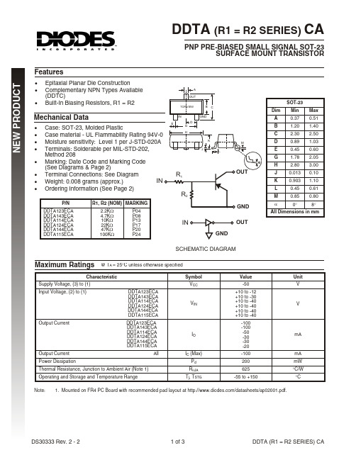
DDTA (R1 = R2 SERIES) CA
NEW PRODUCT
Pd, POWER DISSIPATION (MILLIWATTS)
Output Current
All
Power Dissipation
Thermal Resistance, Junction to Ambient Air (Note 1)
Operating and Storage and Temperature Range
Symbol VCC
VIN
IO
IC (Max) Pd RqJA
J 0.013
K 0.903 1.10
L
0.45 0.61
M
0.85 0.80
a
0°
8°
All Dimensions in mm
SCHEMATIC DIAGRAM
Maximum Ratings @ TA = 25°C unless otherwise specified
Characteristic
hFE, DC CURRENT GAIN (NORMALIZED)
TYPICAL CURVES - DDTA143ECA
250
200
150
100
1467A 产品说明书
Product: 1467A
Inst, 8 Pr #18+1c #22 Str BC, PVC Ins E1, OS, Blk PVC Jkt, 300V PLTC ITC CMG
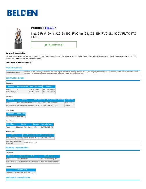
Product Description UL Instrumentation, 8 Pair 18+22AWG (7x26+7x30) Bare Copper, PVC Insulation E1 Color Code, Overall Beldfoil® Shield, Black PVC Outer Jacket, PLTC ITC CMG AWM 2464 SUN RES DIR BUR
DTC123JCA中文资料

DTC123JSA
TO-92S
l Any changing of specification will not be informed individua
of 2
Elektronische Bauelemente
DTC123JE/DTC123JUA/DTC123JKA DTC123JCA/TC123JSA
NPN Digital Transistors (Built-in Resistors)
Absolute maximum ratings(Ta=25℃)
Parameter Supply voltage Input voltage Output current Power dissipation Junction temperature Storage temperature Symbol VCC VIN IO IC(MAX) Pd Tj Tstg 150 E Limits (DTC123J□ UA KA 50 -5~12 100 100 200 150 -55~150 300 ) CA SA Unit V V mA mW
PIN CONNENCTIONS AND MARKING
DTC123JE DTC123JUA
SOT-523
Abbreviated symbol: E42
SOT-323
Abbreviated symbol: E42
DTC123JKA
DTA114ECA DTC123JCA
SOT-23-3L Abbreviated symbol: E42 SOT-23 Abbreviated symbol: E42
℃ ℃
Electrical characteristics (Ta=25℃)
DTD123TKT146;中文规格书,Datasheet资料

lOutline
SMT3
Collector
Base Emitter
DTD123TK SOT-346 (SC-59)
lInner circuit
D
A c
Q
e
b
x SA
A3 e
E HE L1 Lp
Data Sheet
A1 A
l1 e1
S b2
Patterm of terminal position areas
DIM
MILIMETERS
MIN
MAX
A
1.00
1.30
A1
0.00
0.10
A3
0.25
b
0.35
0.50
c
0.09
0.25
D
2.80
3.00
25ºC
-40ºC
0.001
0
0.5
1
1.5
BASE TO EMITTER VOLTAGE : VBE (V)
COLLECTOR CURRENT : IC (mA)
Data Sheet
Fig.2 Grounded emitter output characteristics
500 Ta=25ºC
400
Typ. -
250 2.2
200
Max. -
0.5 0.5 0.3 600 2.86
-
Unit V V V mA mA V kW
MHz
© 2012 ROHM Co., Ltd. All rights reserved.
DTII(A)型手册
1.5.1 输送带
输送带的品种规格符合《GB/T4490—1994运输带尺寸》、《GB/T7984—2001输送带 具有橡胶或朔料覆盖层的普通用途织物芯输送带》和《GB/T9770—2001普通用途钢丝绳芯输送带》的规定,见表1-4
表 1-4 输 送 带
种类
抗拉体强度
/(N/mm.层)
该产品代号将打印在产品铭牌上。已开发的产品规格见表1-2.
表1-2 产品规格(已开发部分)
序
号
输送机
代号
带宽
/mm
传动滚
筒直径
/mm
传动滚筒
许用扭矩
/kN.m
序
号
输送机
代号
带宽
/mm
传动滚
筒直径
/mm
传动滚筒
许用扭矩
/kN.m
1
5050
500
500
2.7
29
12063.1
1200
630
12
2
6550.1
20
51
140100.3
1400
1000
40
24
100100.3
1000
1000
27
52
140100.4
1400
1000
52
25
100100.4
1000
1000
40
53
140100.5
1400
1000
66
26
100100.5
1000
1000
52
54
140125.1
1400
1250
40
27
100125
- 1、下载文档前请自行甄别文档内容的完整性,平台不提供额外的编辑、内容补充、找答案等附加服务。
- 2、"仅部分预览"的文档,不可在线预览部分如存在完整性等问题,可反馈申请退款(可完整预览的文档不适用该条件!)。
- 3、如文档侵犯您的权益,请联系客服反馈,我们会尽快为您处理(人工客服工作时间:9:00-18:30)。
0.2
0.2
0.5 0.5
0.15
1.0
Abbreviated symbol : E32
2.9
1.1
0.4
0.8
(3)
0.8 1.6 0.1Min.
(1) GND (2) IN (3) OUT
1.6 2.8 0.3Min.
1.25 2.1 0.1Min.
ROHM : UMT3 EIAJ : SC-70
Rev.A
3/3
元器件交易网
Appendix
Notes
No technical content pages of this document may be reproduced in any form or transmitted by any means without prior permission of ROHM CO.,LTD. The contents described herein are subject to change without notice. The specifications for the product described in this document are for reference only. Upon actual use, therefore, please request that specifications to be separately delivered. Application circuit diagrams and circuit constants contained herein are shown as examples of standard use and operation. Please pay careful attention to the peripheral conditions when designing circuits and deciding upon circuit constants in the set. Any data, including, but not limited to application circuit diagrams information, described herein are intended only as illustrations of such devices and not as the specifications for such devices. ROHM CO.,LTD. disclaims any warranty that any use of such devices shall be free from infringement of any third party's intellectual property rights or other proprietary rights, and further, assumes no liability of whatsoever nature in the event of any such infringement, or arising from or connected with or related to the use of such devices. Upon the sale of any such devices, other than for buyer's right to use such devices itself, resell or otherwise dispose of the same, no express or implied right or license to practice or commercially exploit any intellectual property rights or other proprietary rights owned or controlled by ROHM CO., LTD. is granted to any such buyer. Products listed in this document are no antiradiation design.
−1 lO/lI=20
−500m Ta=100°C
−200m
25°C −40°C
−100m
−50m
−20m −10m −5m
−2m −1m −100µ −200µ −500µ −1m −2m
−5m −10m −20m −50m −100m
OUTPUT CURRENT : IO (A)
Fig.4 Output voltage vs. output current
(1) GND (2) OUT (3) IN
Rev.A
1/3
元器件交易网
Transistors
DTA123JM / DTA123JE / DTA123JUA DTA123JKA / DTA123JSA
zPackaging specifications
Package Packaging type Code
(1)
(1) GND
0.15
(2) IN
(3) OUT
Each lead has same dimensions
Abbreviated symbol : E32
3.0
3Min.
(15Min.)
ROHM : SPT EIAJ : SC-72
0.45
2.5 5.0
0.5 0.45
(1) (2) (3)
Abbreviated symbol : A123JS
−100 VO=−0.3V
−50
INPUT VOLTAGE : VI(on) (V)
−20
−10
−5
Ta=−40°C
−2
25°C 100°C
−1
−500m
−200m −100m
−100µ −200µ −500µ −1m −2m −5m −10m −20m −50m −100m OUTPUT CURRENT : IO (A)
∗ Characteristics of built-in transistor
Symbol VI(off) VI(on) VO(on) II IO(off) GI R1 R2/R1 fT ∗
Min. −
−1.1 − − − 80
1.54 17 −
Typ. − −
−0.1 − − − 2.2 21
250
Max. −0.5
− −0.3 −3.6 −0.5
− 2.86 26
−
Unit
V
V mA µA − kΩ − MHz
Conditions VCC=−5V, IO=−100µA VO=−0.3V, IO=−5mA IO/II=−5mA/−0.25mA VI=−5V VCC=−50V, VI=0V VO=−5V, IO=−10mA
3000
3000
−
−
−
−
−
−
−
−
SPT Taping
TP
5000
− − − −
zEquivalent circuit
R1 IN
R2
OUT GND(+)
IN
OUT
GND(+)
zAbsolute maximum ratings (Ta=25°C)
R1=2.2kΩ, R2=47kΩ
Parameter
Supply voltage Input voltage
VMT3 Taping
T2L
Part No.
Basic ordering unit (pieces)
8000
DTA123JM
DTA123JE
−
DTA123JUA
−
DTA123JKA
−
DTA123JSA
−
EMT3 Taping
TL 3000
−
− − −
UMT3 Taping T106
SMT3 Taping T146
− − VCE=−10V, IE=5mA, f=100MHz
Rev.A
2/3
元器件交易网
Transistors
DTA123JM / DTA123JE / DTA123JUA DTA123JKA / DTA123JSA
zElectrical characteristic curves
zStructure PNP epitaxial planar silicon transistor (Resistor built-in type)
zExternal dimensions (Unit : mm)
DTA123JM
1.2 0.32
(3)
0.2 0.8 0.2 1.2
ROHM : VMT3
Output current
Power dissipation Junction temperature Storage temperature
Limits
Symbol
Unit
DTA123JM DTA123JE DTA123JUA DTA123JKA DTA123JSA
VCC
−50
V
VIN
−12 to +5
DTA123JUA
0.22
(1)(2)
0.4 0.4 0.8
0.13 0.5
Abbreviated symbol : E32
2.0 0.3
(3)
0.9 0.2 0.7
(1) IN (2) GND (3) OUT
DTA123JE
ROHM : EMT3
DTA123JKA
1.6
0.7
0.3