数据手册_HR7P187_Datasheet_C V2.1
福禄克187万用表维修手册_主板关键测试点说明书
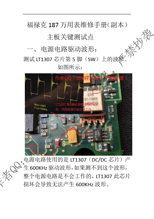
福禄克187万用表维修手册(副本)主板关键测试点一、电源电路驱动波形:测试LT1307芯片第5脚(SW)上的波形。
如图所示:电源电路使用的是LT1307(DC/DC芯片)产生600KHz驱动波形,如果测不到这个波形,整个电源电路是不会工作的,LT1307此芯片损坏会导致无法产生600KHz波形。
二、主时钟驱动波形。
测试7.37MHz晶振两端波形,为7.3M正弦波,如果这个晶振损坏或者没有波形,则整机无法正常工作(此晶振是给FLUKE2000单片机芯片提供时钟信号)。
93C56(EEPROM芯片)供电电压来自钽电容的3V供电。
提示:以上所有测试点都是以电源负极为参考点测量的电压和波形。
三、显示驱动芯片时钟波形。
FLUKE1998是LCD液晶屏驱动芯片,此芯片旁边有一颗32.768KHz的实时时钟晶振,此晶振波形为32K正弦波。
此32.768KHz实时时钟晶振如果损坏,会导致显示不正常,(FLUKE1998)液晶屏驱动芯片本身损坏也会导致显示不正常。
四、(主控芯片)/液晶屏驱动芯片供电电压。
FLUKE1998是液晶屏驱动芯片。
FLUKE2000是主控芯片(MCU)。
FLUKE1998(液晶屏驱动芯片)的供电是(TPS77030)LDO芯片输出的3.3V经过管子转换为3.09V左右的供电提供给液晶屏驱动芯片供电。
FLUKE2000(主控芯片)的供电来自电源电路中的钽电容产生的3.11V提供给主控芯片供电。
测试点如果图所示:↓五、模拟芯片(FLUKE669918)供电和基准电压。
FLUKE669918(模拟芯片),此芯片内部集成了:A/D转换,真有效值(RMS)模块,功能测量都是这个芯片完成的。
FLUKE669918芯片的供电电压来自TPS77001(LDO)芯片输出的5V供电。
LMC6042双运算放大器的供电电压也来自TPS77001输出的5V 供电。
REF43G是电压基准芯片,该芯片的6脚输出2.5V基准电压提供给FLUKE669918芯片内部的A/D转换电路基准电压。
MT78740 02-2017 数据手册说明书

MTMT00A08-1415034-19-1415043-17-1393163-37-1415043-1 8-1393163-3MTMT00A0..MT7874002-2017, Rev. © 2015 Tyco Electronics Corporation,a TE Connectivity Ltd. company Datasheets and product specification according to IEC 61810-1 and to be used only together with the ‘Definitions’ section.Datasheets and product data is subject to the terms of the disclaimer and all chapters of the ‘Definitions’ section, available at /definitionsDatasheets, product data, ‘Definitions’ sec-tion, application notes and all specifications are subject to change.1SCHRACKn Snap-on mounting on DIN-rail n Screw mountingn Pozidrive screws with rising clamp terminals n Logical layout of input-/output connections n White marking areaMT DIN-rail sockets with screw-type terminalsMT 78 750 MT3 DIN-rail socket with screw-type terminals, 11-pin MT 78 755 MT2 DIN-rail socket with screw-type terminals, 8-pinMT78 760 MT3 DIN-rail socket with screw-type terminals, 11-pinMT 78 740 MT3 DIN-rail socket with screw-type terminals, 11-pin MT 78 745 MT2 DIN-rail socket with screw-type terminals, 8-pinGeneral Purpose Relays AccessoriesAccessories Multimode Relay MTZF0235-BF0103-BS0414-AB S0414-ACF0103-BS0311-BB S0414-AAF0200-BS0366-ASocket system MT 78 740 and MT 78 745n 8/11 pin socket for MT2 / MT3n Double A2 screw for simple further connection of coil supplyZ Zb02-2017, Rev. 0217© 2015 Tyco Electronics Corporation, a TE Connectivity Ltd. company Datasheets and product specificationaccording to IEC 61810-1 and to be usedonly together with the ‘Definitions’ section.Datasheets and product data is subject to theterms of the disclaimer and all chapters ofthe ‘Definitions’ section, available at/definitionsDatasheets, product data, ‘Definitions’ sec-tion, application notes and all specificationsare subject to change.2SCHRACKType Part NumberMT 28 800Metal retaining clip MT 8-1393163-0LED and Protection modules for MT 78 740, MT 78 745Type Part NumberMTM T0 0A0Protection diode 1N4007 (A1+, A2-) 7-1393163-6MTM U0 730RC-network 110...230 VAC 7-1393163-8MTM L0 024red LED 24 VAC / VDC 7-1393163-4Function modules for MT 78 740, MT 78 745Type Part NumberMTM Z0 W00 Delay ON 7-1393163-9MTM F0 W00Multifunction 7-1393163-3Technical data - Function modulesNominal voltage 24...240 VDC / VACMains frequency 48...63 HzPrecision of time setting + 0.5 %Readiness for repetition ≤ 0.5 % or 5 msInfluence of temperature ≤ 0.1 %/°CTime range switchable 0.05s...240h in 8 rangesMaterial compliance: EU RoHS/ELV, China RoHS, REACH, Halogen contentrefer to the Product Compliance Support Center at/customersupport/rohssupportcenterAmbient temperature range -25…+55˚CGeneral Purpose RelaysAccessoriesAccessories Multimode Relay MT (Continued)ApprovalsVDE Cert. No. 40009096, cULus E135149Technical data MT78 750/755/760/740/745Rated voltage/Max. switching voltage AC 240/400 VACRated current 10 ADielectric strengthcoil-contact circuit 2500 V rmsopen contact circuit 1500 V rmsadjacent contact circuit 2500 V rmsClearance / creepage coil-contact circuit ≥ 2.8/4 mmMaterial group of insulation parts IIIaInsulation to IEC 60664-1Type of insulation coil-contact circuit basicopen contact circuit functionaladjacent contact circuits basicRated insulation voltage 250 VPollution degree 2Rated voltage system 230/400 VOvervoltage category IIIMaterial compliance: EU RoHS/ELV, China RoHS, REACH, Halogen contentrefer to the Product Compliance Support Center at/customersupport/rohssupportcenterAmbient temperature range -20…+80˚CTerminals screwTerminal screw torque acc. IEC 61984 0.5 Nmmax. 0.7 NmWire strip length 9 mmWire cross sectionsingle wire 2 x 2.5 mm2fine wire 2 x 2.5 mm2with bootlace crimp (DIN 46228/1) 2 x 1.5 mm2Insertion cycles A (10)Max. Insertion Force total 100 NMounting distance ≥ 0 mm, dense packingWeightMT 78 750/760 54 gMT 78 755 47 gMT 78 740 62 gMT 78 745 56 gPackaging unit 25 pcsDIN-rail sockets with screw-type terminalsType Part NumberMT 78 750DIN-rail socket with screw-type 1415035-1terminals, 11-pinMT 78 755DIN-rail socket with screw-type 3-1415035-1terminals, 8-pinMT 78 760DIN-rail socket with screw-type 8-1415034-1terminals, 11-pinMT 78 740DIN-rail socket with screw-type 8-1393163-3terminals, 11-pinMT 78 745DIN-rail socket with screw-type8-1393163-4F0201-BF0203-BF0204-B02-2017, Rev. 0117© 2015 Tyco Electronics Corporation, a TE Connectivity Ltd. company Datasheets and product specificationaccording to IEC 61810-1 and to be usedonly together with the ‘Definitions’ section.Datasheets and product data is subject to theterms of the disclaimer and all chapters ofthe ‘Definitions’ section, available at/definitionsDatasheets, product data, ‘Definitions’ sec-tion, application notes and all specificationsare subject to change.3SCHRACKFunction modules for MT 78 740, MT 78 745FunctionDelay ONDelay OFFsingle shot leading edgesingle shot trailing edgeDelay ONtriggerd by signal contactsingle shotflasher starting with pauseflasher starting with pulseAccessories Multimode Relay MT(Continued)Technical data MT78 602/603/612/613Rated voltage/Max. switching voltage AC 240/400 VACRated current 10 ADielectric strengthcoil-contact circuit 2500 V rmsopen contact circuit 1500 V rmsadjacent contact circuits 2500 V rmsClearance / creepage coil-contact circuit ≥ 2.8/4 mmMaterial group of insulation parts IIIaInsulation to IEC 60664-1Type of insulation coil-contact circuit basicopen contact circuit functionaladjacent contact circuits basicRated insulation voltage 250 VPollution degree 2Rated voltage system 230/400 VOvervoltage category IIIMaterial compliance: EU RoHS/ELV, China RoHS, REACH, Halogen contentrefer to the Product Compliance Support Center at/customersupport/rohssupportcenterAmbient temperature range -40…+70˚CTerminals pcb, solder terminalsInsertion cycles A (10)Max. Insertion Force total 100 NMounting distance ≥ 0 mm, dense packingResistance to soldering heat 270°C/10sWeight 7 gPackaging unit 25 pcsSockets with solder and PCB terminalsType Part NumberMT 78 612Socket 8-pin with solder terminals 7-1415043-1MT 78 613Socket 11-pin with solder terminals 8-1415043-1MT 78 602Socket 8-pin with PCB terminals 9-1415043-1MT 78 603Socket 11-pin with PCB terminals 1415044-1MT 78 613Socket 11-pin with solder terminalsMT 78 603Socket 11-pin with PCB terminalsF0107-AS0309-AAF0104-AS0309-ABF0105-AS0309-ACF0106-AS0309-ADGeneral Purpose RelaysAccessoriesMTMT00A08-1415034-19-1415043-17-1393163-37-1415043-1 8-1393163-3MTMT00A0..MT78740。
MAX187中文资料

MAX187/189 中文资料+5V,低功耗,12位串行ADC一般描述:MAX187/MAX189串行12位模数转换器可以在单5V电源下工作,接受0-5V的模拟输入。
MAX187,189均为逐次逼近式ADC,快速采样/保持(1.5uS),片内时钟,高速3线串行接口。
MAX187/MAX189转换速度为75Ksps。
通过一个外部时钟从内部读取数据,并可省却外部硬件而与绝大多数的数字信号处理器或微控制器通讯。
接口与SPI,QSPI,和Microwire 兼容。
MAX187有内部基准,MAX189则需要一个外部基准。
MAX187和MAX189采用节约空间的8脚DIP和16脚SO封装。
电源消耗为7.5mW,在关断模式下可以减少至10uW。
优异的AC特性和极低的电源消耗,同时及其容易的使用和较小的封装尺寸使得MAX187/189能理想的应用于远程DSP和传感器,或者应用于对电源消耗和空间极为苛刻的地方。
应用范围:移动式数据处理(Portable Data Logging)远程数字信号处理(Remote Digital Signal Processing)隔离数据获取(Isolated Data Acquisition)高精度处理控制(High-Accuracy Process Control)特性:12位精度±1/2 LSB完整非线性(Integral Nonlinearity)(MAX187A/MAX189A)内部采样/保持电路,75KHz采样速率单+5V电源工作低功耗:关断模式下2uA5mA操作电流内部4.096V基准(MAX187)3线串行接口,SPI,QSPI和Microwire兼容小管脚8脚DIP和16脚SO封装。
定购信息:功能框图:管脚配置:极限指标:电气特性:(VDD = +5V ±5%; GND = 0V; unipolar input mode; 75ksps, fCLK = 4.0MHz, external clock (50% duty cycle); MAX187—internal reference: VREF = 4.096V, 4.7µF capacitor at REF pin, or MAX189—external reference: VREF = 4.096V applied to REF pin, 4.7µF capacitor at REF pin; TA = TMIN to TMAX; unless otherwise noted.)时序特征(TIMING CHARACTERISTICS):典型操作特征:管脚描述:细节描述:1,转换器操作:MAX187/MAX189使用采样/保持(T/H)和逐次逼近寄存器(SAR)电路来转换模拟量至12位数字量输出。
1n5711-t数据表.pdf说明书

1/3®1N5711SMALL SIGNAL SCHOTTKY DIODEOctober 2001 - Ed: 1BSymbol ParameterValue Unit V RRM Repetitive Peak Reverse Voltage 70V I F Forward Continuous Current*T a = 25°C 15mA P tot Power Dissipation*T a = 25°C430mW T stg T j Storage and Junction Temperature Range- 65 to 200- 65 to 200°C T LMaximum Lead Temperature for Soldering during 10s at 4mm from Case230°CABSOLUTE RATINGS (limiting values)Symbol Test ConditionsValue Unit R th(j-a)Junction-ambient*400°C/WTHERMAL RESISTANCE* On infinite heatsink with 4mm lead length **Pulse test: t p ≤300µs δ<2%.Matched batches available on request. Test conditions (forward voltage and/or capacitance) according to customer specification.Symbol Test Conditions Min.Typ.Max.Unit V BR T amb = 25°C I R = 10µA 70V V F * *T amb = 25°C I F = 1mA 0.41VT amb = 25°CI F = 15mA 1I R * *T amb = 25°CV R = 50V0.2µASTATIC CHARACTERISTICSELECTRICAL CHARACTERISTICS Symbol Test Conditions Min.Typ.Max.Unit C T amb = 25°C V R = 0V f = 1MHz 2pF τT amb = 25°CI F = 5mAKrakauer Method100psDYNAMIC CHARACTERISTICSMetal to silicon junction diode featuring high break-down, low turn-on voltage and ultrafast switching.Primarly intended for high level UHF/VHF detec-tion and pulse application with broad dynamic range. Matched batches are available on requestDESCRIPTION1N5711Fig.1:Forward current versus forward voltage atlow level (typical values).Fig.2:Capacitance C versus reverse applied voltage V R (typical values).Fig.3:Reverse current versus ambient tempera-ture.Fig.4:Reverse current versus continuous reverse voltage (typical values).Cooling method : by convection and conductionMarking: clear, ring at cathode end.Weight: 0.15gInformation furnished is believed to be accurate and reliable.However,STMicroelectronics assumes no responsibility for the consequences of use of such information nor for any infringement of patents or other rights of third parties which may result from its use.No license is granted by implication or otherwise under any patent or patent rights of STMicroelectronics.Specifications mentioned in this publication are subject to change without notice. This publication supersedes and replaces all information previously supplied.STMicroelectronics products are not authorized for use as critical components in life support devices or systems without express written approval of STMicroelectronics.The ST logo is a registered trademark of STMicroelectronics© 2001 STMicroelectronics - Printed in Italy - All rights reserved.STMicroelectronics GROUP OF COMPANIESAustralia - Brazil - China - Finland - France - Germany - Hong Kong - India - Italy - Japan - Malaysia Malta - Morocco - Singapore - Spain - Sweden - Switzerland - United Kingdom - U.S.A.。
FLUKE187、189真有效值多用表校准手册(中文版)

自购买日起十年内,本保证也包括LCD。十年以后直到仪表的终生,Fluke将以收费的方式更换 DMM的LCD(根据当时该组件的成本价格收取费用)。
欲建立原购买者与购买日期的根据,请填妥并寄回产品所附上的注册登记卡,或在 上注册产品。对于从Fluke授权销售处以适当的国际价格所购买而损坏的 产品,Fluke可选择免费修理、更换或以原购买价退款的方式处理该产品。若产品是从一个国家 购买却被送到其它地区修理,Fluke保留收取修理/更换零件的进口费用的权利。
dBm功能用户可以选择参考电阻。 显示具有读数保持功能 蜂鸣器在电阻低于阈值或电路瞬间开路时会发出响声。 从峰值到零之间共分 51 段 以%数或毫秒单位来测量信号的开启或关闭时间 记录最大、最小和平均值. 24小时钟用来记录MAX或MIN测量值的发生时间,平均值的经历时间 FAST MN MX 模式能够捕获 250 微秒的峰值
特性概要…………………………………………………………………5
基本技术指标…………………………………………………………………6
详细精度技术指标……………………………………………………………7
频率计数器灵敏度……………………………………………………………10
负载电压(A,mA,μA)…………………………………………………10
FAST MN MX(24小时时标) 闭壳校准 Battery / Fuse盖 高强度注模外壳
描述
主显示:
50,000 字
次显示:
5,000 字
条状图:
51 端, 更新速率 40 次/秒
白色背光在照明条件不好的环境中可以提供清晰的读数。
在测量过程中数表会立即选择正确的量程
选择交流、交流和直流双显示或交流+直流测量读数
1N1732A 数据手册说明书
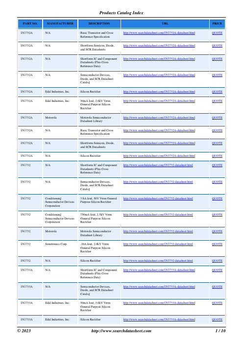
MANUFACTURER
DESCRIPTION
URL
N/A
Basic Transistor and Cross
/1N1732A-datasheet.html
Reference Specification
N/A
Shortform Semicon, Diode,
Diode, and SCR Datasheet
Catalog
Conditioning Semiconductor Devices Corporation
3.6A Iout, 50V Vrrm General Purpose Silicon Rectifier
/1N1732-datasheet.html
© 2023
PRICE QUOTE QUOTE QUOTE QUOTE QUOTE QUOTE QUOTE QUOTE QUOTE QUOTE QUOTE QUOTE QUOTE QUOTE QUOTE QUOTE QUOTE QUOTE QUOTE QUOTE QUOTE
/1N1733-datasheet.html
Semitronics Corp.
High Voltage Axial Lead Silicon Cartridge Rectifiers
/1N1733-datasheet.html
Motorola Semiconductor Datasheet Library
/1N1733A-datasheet.html
N/A
Basic Transistor and Cross
/1N1733A-datasheet.html
/1N1733A-datasheet.html
Reference Specification
HE17x Series USB Data Logger User Manual
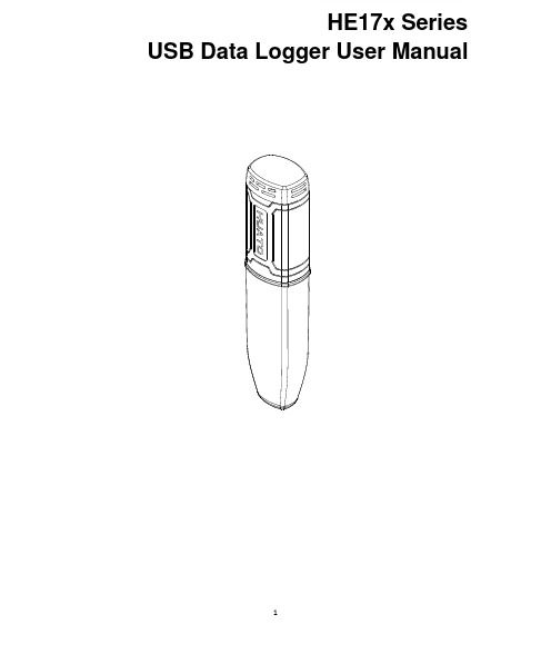
1HE17x SeriesUSB Data Logger UserManualCONTENTSB Data Logger Hardware (3)1.1Introduction (3)1.2Features (3)1.3Application (3)1.4USB Data Logger Model (3)1.5USB Temperature Data Logger Appearance(HE170/HE171/HE172) (4)1.6USB Temperature Data Logger Screen(HE170/HE171/HE172) (4)1.7USB Temperature&Humidity Data Logger Appearance(HE173/HE174) (5)1.8USB Temperature&Humidity Data Logger Screen(HE173/HE174) (5)1.9Button (6)1.10Install Battery (6)1.11Fix USB Data Logger (6)Chapter2.Logpro Software (7)2.1The Requirement of the Computer Hardware (7)2.2Install Driver&Software (7)2.3Setting the logger’s properties to start a new measurement (8)2.4Properties Description (9)2.5Start record time description (10)2.6Download the Records after a Measurement (10)2.7Data Listing Window (12)2.8Exporting Logs from Logpro (12)2.9Delete Records in the Logger (13)2.10Check the Save File in File List (13)Chapter3.Attention (14)Chapter4.FAQ (14)4.1LCD Screen Dim (14)4.2Data&Time Error (14)4.3Software"Runtime Error" (14)4.4Check COM Port Number (14)B Data Logger Hardware1.1IntroductionHE170USB series has USB interface,enjoying elegant appearance and compact construction,specially designed for refrigerator and cold-chain transportation as well as container transport applications.HE170USB series adopts friendly USB interface,friendly mounting bracket and the screws.HE170USB series can show temperature/temperature and humidity simultaneously as well as the battery indication.The OK key can help to check the Max/Min/Current value and the upper and lower limits.1.2Features⏹Waterproof and dustproof standard IP67,resisting moisture and dust.⏹Can set temperature and humidity limit value and LED lights will flash when the valuebeing exceeded.⏹Lower consumption design,1/2AA3.6V Lithium battery,working for12months and easyto replace.(Logging Interval:600s)⏹Transfer logging data to PC through software and can be saved as different types toensure the existence.⏹Use high sensitivity sensor,fast reaction and high precision.⏹Size(L x H x D):126mm x34mm x28mm1.3ApplicationWildly use in cold chain Transportation,Containers.1.4USB Data Logger Model1.5USB Temperature Data Logger Appearance(HE170/HE171/HE172)8①LCD Screen⑥Battery Replacement Position.②Button⑦Waterproof Transparent Cover③LED Warming Light When the⑧Fixed BracketTemperature Value Exceeds SettingLimits.④USB Connection Port⑨Model Label⑤Waterproof Ring1.6USB Temperature Data Logger Screen(HE170/HE171/HE172)①Display the High Limit⑤Display the Maximum Value inRecords②Display the Low Limit⑥symbol display shows being thelogging status.③Battery power indication.⑦Temperature Value④Display the Minimum Value in⑧Temperature Unit(℃or℉)Records1.7USB Temperature&Humidity Data Logger Appearance(HE173/HE174)8①LCD Screen⑥Battery Replacement Position.②Button⑦Waterproof Transparent Cover③LED Warming light When the⑧Fixed BracketTemperature or Humidity ValueExceeds the Setting Limits.④USB Connection Port⑨Model Label⑤Waterproof Ring1.8USB Temperature&Humidity Data Logger Screen(HE173/HE174)①Display the High Limit⑤Battery power indication.②Display the Low Limit⑥Units symbol display℃or℉,%RH③Display the Maximum Value in⑦ValueRecords④Display the Minimum Value inRecords1.9ButtonOK Button1.Press this button for long to 5seconds can turn on/off the logger.2.Check the MAX;MIN;High &Low values as well as the current value in the working status.1.10Install Battery1.Open the Battery Cover2.Remove shell3.Install Battery1.11Fix USB Data Loggere Screw to Fix the Bracket onto the Wall.2.Install the Data Logger.Chapter 2.Logpro Software2.1The Requirement of the Computer Hardware1.OS:Windows2000/XP/Vista/Win7/Win8/Win10(32/64-bit ),nonsupport Linux/UnixOS.2.CPU:1.6GHz3.Physical Memory:512MB4.Hard-drive Space:4GBB Port:12.2Install Driver &Software1.Install DriverPut the assigned software disc into the computer driver and open the file tofindand select the driver based on the operating system.OS Win7/Win8/Win10-64select “CH341SER[64bit]”.OS Win XP;Vista;Win7-32select “CH341SER[32bit]”(1)Click 【CH341SER 】;(2)Click 【INSTALL 】—【Confirm】2.Install Logpro SoftwareNotice:Please Install Logpro Software inD:\2.3Setting the logger’s properties to start a new measurement.1.Connect the data logger to the computer.12.Running Logpro software on the PC.3.From the toolbar select Connect.24.Read the logger’s properties.5.Set the properties.6.Sync the properties &time.(The PC time will be synchronized to the logger as well.)7.From the toolbar select Disconnect8.Unplug the logger from the Computer,and then the logger is in Standby mode 3.9.Press OK button on the logger,turn on the Data Logger and start recording.1The windows operating system cannot handle USB devices being unplugged and plugged back too fast.When unplugging the logger,wait for about 5seconds before plugging it in again.If you unplug and plug back a device too quickly,the computer may stop recognizing any USB devices on that port.If this happens you will have to restart the computer.This is a windows USB problem and is not related to Logpro.2If more than one logger is connected to your computer at the same time,the program will ask you to choose COM port manually.3The logger has three modes:1.LOG:In the mode,the logger samples and records data timely.2.Standby:In the mode,the logger stops to sample and record,and the LCD display is OFF.3.OFF:In the mode,the logger stops to sample and record,and the LCD display is off.Logpro cannot connect to the logger also.654732.4Properties DescriptionProperty Text DescriptionName English letters orNumbersName of the loggerSN10Characters Must be the same as the one in the label oflogger.Sampling Interval(s)Number from1to240Sampling frequency in LCD screenLogging Interval(s)Number from2to86400Logging frequency.Logs The count of records in the memory.Capacity The total capacity of the logger’s storage. Temperature type℃The unit of temperature is centigrade℉The unit for Fahrenheit temperatureStart Mode Start Now Start log when the Logger was turn ON.Delay Start Wait Delay Time then start log.Timing Start Start log when Delay Time:HHMMSSe.g.170000means17:00:00Delay Time Input a Delay Time or Timing Time.High&Low Limit CH1:TemperatureCH2:Humidity When the value over the limit,the buzz will sounds and alarm.Offset4CH1:TemperatureCH2:Humidity Input positive number to decrease the value. Input negative number to increase the value.4Calibrate the logger:The logger is factory calibrated to an accuracy given in the device specifications.However, there may be times when you wish to adjust the calibration of your logger.Logpro provides you with the ability to perform a single point offset calibration.This calibration can be used to increase the accuracy of the logger for a restricted data range.2.5Start record time description1.Select the mode to start the record in the property bar:Start Now:the recorder starts immediately to record the data.Delay start:the recorder starts to record the data after the set delay time.Timing start:the recorder starts recording data at the specified time point.(Note:the recorder will start at the turn on state and the recorder will not start the record automatically when the logger at the turn off state).2,Entry delay time or timing time in the property bar.Start Now:the default is0.Delay start:fill in the delay time,the unit is second.For example,fill in120indicates that the instrument starts to record the data after turn on logger two minutesTiming start:fill in the timing time and fill in the format of HHMMSS.For example,fill180000 indicates that the instrument starts to record the data at6:00:00pm3,Synchronization property and time(The PC time will also be synchronized to the recorder).2.6Download the Records after a Measurement.10.Connect the data logger to a free USB port on the computer.11.Running Logpro software on the PC.12.From the toolbar select Connect.13.From the toolbar select Download1213Once the data is transferred from the logger to the PC,the data graph will be displayed.The graph display will be blank if there are not any logs.Tips:Press and hold the left mouse button to drag a box,when the left mouse button is released,the graph will be redraw with the data in the selected rectangle area(Magnified data table).Click right button,then the graph will be redrawing with all the data in thelogs file.2.7Data Listing WindowClick"Data List"button on the toolbar,and then the data listing window is shown below. Channel3unit is Dew Point.The Value is calculated from temperature&humidity.The data pane lists the data samples collected by the logging device.The column width of each column is adjustable by using the left mouse button and dragging the column the desired width.2.8Exporting Logs from Logpro●:Export data list to an Excel file.●:Export data list to a PDF file.●:Export graph to a BMP file.2.9Delete Records in the Logger14.From the toolbar select Delete 5142.10Check the Save File in File List15.From the toolbar select Filelist.616.Click to open the file.1516●Double click left mouse button,then the selected file is opened.●Click right mouse button,a popup menu is shown as below,you can rename or delete orlog file.●The save file is saved in the Logpro software’s installation path in the PC’s hard driver.5Clear the logger's memory.It will not affect downloaded file.6These files are located in the installed path of Logpro.Chapter3.Attention●HE17x water proof level is IP67.Do not put it into the water.●HE17x plastic shell is ABS,flame retardant,not resistant to acid and alkali.●If repair is needed,only authorized technician could do the repair.●The instrument configuration by1x ER14250lithium battery(3.7V)is not rechargeable.●USB power supply(5V)cannot let the Data Logger work.Chapter4.FAQ4.1LCD Screen DimReason:●Insufficient battery or the environment temperature is too low or too high.Solution:●In the case of insufficient battery,please replace the battery.If resulted from environmenttemperature,please immediately take the logger out of the environment.4.2Data&Time ErrorReason:●The battery level is low●The data logger is not synchronous properties,before start recording.Solution:●Replace the battery.●Please sync the properties,before start recording.4.3Software"Runtime Error"Reason:●OS forbid software creating files.Solution:●Run the program(software)as an administrator.●Install software in Disk D:\●A data logger name cannot contain any of the following characters:\/:*?"<>|●Software’s installation path cannot include Chinese character or garbage character.4.4Check COM Port Number●Press“Win”+“R”in keyboard->Run"devmgmt.msc"to Open"Device Manager"inWindows->Expand"Ports(COM&LPT)"->"USB-SERIAL CH340(COM No.)"is the Data Logger。
sth35数据手册
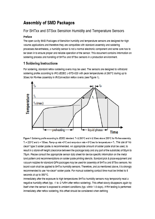
Assembly of SMD PackagesFor SHTxx and STSxx Sensirion Humidity and Temperature SensorsPrefaceThe open cavity SMD Packages of Sensirion humidity and temperature sensors are designed for high volume applications and therefore they are compatible with standard assembly and soldering processes.Nevertheless, a humidity sensor is not a normal electronic component and some care has to be taken in to ensure proper and reliable operation of the sensor. This document contains information on soldering process and handling of SHTxx and STSxx sensors in a production environment.1 Soldering InstructionsFor soldering, standard reflow soldering ovens may be used. The sensors are designed to withstand soldering profile according to IPC/JEDEC J-STD-020 with peak temperatures at 260°C during up to30sec for Pb-free assembly in IR/Convection reflow ovens (see Figure 1).Figure 1 Soldering profile according to JEDEC standard. T P ≤ 260°C and t P ≤ 30sec above 255°C for Pb-free assembly. T L < 220°C and t L < 150sec. Ramp-up rate <3°C and ramp-down rate < 6°C/sec for temperatures > T L. The use of “no clean” type 3 solder paste2 is recommended. An appropriate amount of solder paste shall be used, to result in a stand-off height (clearance between the package body and an y part of the substrate) of 50μm to 75μm. Please consult the appropriate sensor data sheet for device specific information on the metal land pattern and recommendations on solder paste printing stencils. Sandard pick & place equipment and vacuum nozzles for standard QFN packages may be used for assembly of SHTxx and STSxx sensors. No board wash shall be applied to SHTxx humidity sensors. Therefore, and as mentioned above, it is strongly recommended to use “no-clean” solder paste. For manual soldering conta ct time must be limited to 5 seconds at up to 350°C.Immediately after the exposure to high temperatures SHTxx humidity sensors may temporarily read a negative humidity offset (typ. -1 to -2 %RH after reflow soldering). This offset slowly disappears again by itself when the sensor is exposed to ambient conditions (typ. within 1-3 days). If RH testing is performed immediately after reflow soldering, this offset should be considered when definingthe test limits. It is important to note that the diced edge or side faces of the I/O pads may oxidise over time, therefore a solder fillet may or may not form. Hence there is no guarantee for solder joint fillet heights of any kind.2 Storage Conditions and HandlingInstructionsIt is of great importance to understand that a SHTxx humidity sensor is not a standard electronic component and needs to be handled with care. Chemical vapors at high concentration in combination with long exposure times may offset the sensor reading. In manufacturing, transport and operation the sensors shall be prevented of high concentration of chemical solvents and long exposure times. Out-gassing of glues, adhesive tapes and stickers or out-gassing packaging material such as bubble foils, foams, etc. shall be avoided. Manufacturing area shall be well ventilated. For more detailed information please consult the document “Handling Instructions” or contact Sensirion.2 Solder types are related to the solder particle size in the paste: Type3 covers the size range of 25 – 45 µm as specified in IPC J-STD-005A . Revision HistoryDate Version Page(s) Changes26.May 2014 1 all Initial versionCopyright © 2014 by SENSIRIONCMOSens®is a trademark of SensirionAll rights reserved。
- 1、下载文档前请自行甄别文档内容的完整性,平台不提供额外的编辑、内容补充、找答案等附加服务。
- 2、"仅部分预览"的文档,不可在线预览部分如存在完整性等问题,可反馈申请退款(可完整预览的文档不适用该条件!)。
- 3、如文档侵犯您的权益,请联系客服反馈,我们会尽快为您处理(人工客服工作时间:9:00-18:30)。
加强描述:3.2.3,5.1.4,6.1.3,6.5.1,6.5.2, 附录 1.1,附录 2.1,附录 2.2
错误修正:2.1,2.2,4.3,5.1.1.1,5.1.1.2,5.1.2.1, 5.1.2.2,5.4.3,附录 1.3,附录 1.4
V2.1 版权所有©上海海尔集成电路有限公司
4/85
V2.1 版权所有©上海海尔集成电路有限公司
3/85
上海海尔集成电路有限公司
HR7P187 数据手册
版本 V1.0 V2.0
V2.1
修改日期 2010-08-02 2011-03-11
2011-04-26
修订历史
预发行版
更改概要
添加内部时钟电气特性及部分补充说明
2/85
上海海尔集成电路有限公司
HR7P187 数据手册
产品订购信息
型号
程序存储器
HR7P187F4R HR7P187F4R-B
HR7P187F4D HR7P187F4D-B FLASH:2K×15 位
HR7P187F4S HR7P187F4S-B
数据存储器
版权所有©
上海海尔集成电路有限公司
本数据手册的信息在发行时是经过核实并且尽最大努力使之精确的。上海海尔集成电路有限公司不为由于使用本数 据手册而可能带来的风险或后果负责。手册中的实例仅作为说明用途,上海海尔集成电路有限公司不担保或确认这 些实例是合适的、不需进一步修改的、或推荐使用的。上海海尔集成电路有限公司保留不需要通知本数据手册读者 而修改自己产品的权利。如需得到最新的产品信息,请随时用上述联系方式与上海海尔集成电路有限公司联系。
上海海尔集成电路有限公司
HR7P187 数据手册
目录
内容目录
第 1 章 芯片简介 ................................................................................................................ 10 1. 1 概述 ....................................................................................................................... 10 1. 2 应用领域 .................................................................................................................11 1. 3 结构框图 ................................................................................................................ 12 1. 4 管脚分配图............................................................................................................. 13 1. 4. 1 14-pin.............................................................................................................. 13 1. 5 管脚说明 ................................................................................................................ 14 1. 5. 1 管脚封装对照表 .............................................................................................. 14 1. 5. 2 管脚复用说明 .................................................................................................. 15
关于芯片的复位
海尔 MCU 芯片具有内部上电复位。对于不同的快速上/下电或慢速上/下电系统,内部上电复位电路可能失效,建议 用户使用外部复位、下电复位、看门狗复位等,确保复位电路正常工作。在系统设计时,若使用外部复位电路,建 议采用三极管复位电路、RC 复位电路。若不使用外部复位电路,建议采用复位管脚接电阻到电源,或采取必要的 电源抖动处理电路或其它保护电路。具体可参照芯片的数据手册说明。
关于芯片的 ESD 防护措施
海尔 MCU 芯片具有满足工业级 ESD 标准保护电路。建议用户根据芯片存储/应用的环境采取适当静电防护措施。应 注意应用环境的湿度;建议避免使用容易产生静电的绝缘体;存放和运输应在抗静电容器、抗静电屏蔽袋或导电材 料容器中;包括工作台在内的所有测试和测量工具必须保证接地;操作者应该佩戴静电消除手腕环手套,不能用手 直接接触芯片等。
关于芯片的初始化
海尔 MCU 芯片具有各种内部和外部复位。对于不同的应用系统,有必要对芯片寄存器、内存、功能模块等进行初 始化,尤其是 I/O 管脚复用功能进行初始化,避免由于芯片上电以后,I/O 管脚状态的不确定情况发生。
关于芯片的管脚
海尔 MCU 芯片具有宽范围的输入管脚电平,建议用户输入高电平应在 VIHMIN 之上,低电平应在 VILMAX 之下。避免 输入电压介于 VIHMIN 和 VILMAX 之间,以免波动噪声进入芯片。对于未使用的输入管脚,应通过电阻上拉至电源电平 或下拉至地。对于未使用的管脚,建议用户设为输出状态,并通过电阻接至电源或地。对未使用的管脚处理因应用 系统而异,具体遵循应用系统的相关规定和说明。
SRAM:176 x 8 位 EEPROM:256 x 8 位
封装 SSOP10
DIP14 SOP14
HR 7P No. X X X X -B
内部时钟出厂校准电压: 默认不写:5V;- B: 3.3V 版本号:A(默认,不写) 封装:R—SSOP10;D—DIP14; S—SOP14 ROM容量:4—2K X 15位(4K字节)
HR7P187 数据手册
海尔 MCU 芯片使用注意事项
关于芯片的上/下电 海尔 MCU 芯片具有独立电源管脚。当 MCU 芯片应用在多电源供电系统时,应先对 MCU 芯片上电,再对系统其 它部件上电;反之,下电时,先对系统其它部件下电,再对 MCU 芯片下电。若操作顺序相反则可能导致芯片内部
元件过压或过流,从而导致芯片故障或元件退化。具体可参照芯片的数据手册说明。
关于芯片的时钟
海尔 MCU 芯片具有内部和外部时钟源。内部时钟源会随着温度、电压变化而偏移,可能会影响时钟源精度;外部 时钟源采用陶瓷、晶体振荡器电路时,建议使能起振延时;使用 RC 振荡电路时,需考虑电容、电阻匹配;采用外 部有源晶振或时钟输入时,需考虑输入高/低电平电压。具体可参照芯片的数据手册说明。
第 3 章 存储资源 ................................................................................................................ 22 3. 1 程序存储器............................................................................................................. 22 3. 1. 1 概述 ................................................................................................................ 22 3. 1. 2 程序指针PC直接寻址...................................................................................... 22 3. 1. 3 程序指针PC相对寻址...................................................................................... 22 3. 2 数据存储器............................................................................................................. 23 3. 2. 1 数据存储器地址映射 ....................................................................................... 23 3. 2. 2 控制寄存器空间 .............................................................................................. 24 3. 2. 3 寻址方式 ......................................................................................................... 26 3. 2. 4 通用数据存储器 .............................................................................................. 26 3. 2. 5 EEPROM数据存储器 ...................................................................................... 27 3. 2. 5. 1 概述 ..................................................................................................... 27 3. 2. 5. 2 EEPROM写操作 ................................................................................... 27 3. 2. 5. 3 EEPROM读操作 ................................................................................... 29 3. 3 控制寄存器............................................................................................................. 29