ijcep0052131
ACCUSPIN系统-Histopaque 1077产品说明书
Technical BulletinACCUSPIN™ System – Histopaque ® 1077Catalog Numbers A6929, A7054, and A0561Product DescriptionACCUSPIN System-Histopaque -1077products are intended for use in the isolation of lymphocytes and other mononuclear cells. The separation medium, Histopaque-1077, is a sterile-filtered, endotoxin tested solution of polysucrose and sodium diatrizoate, adjusted to a density of 1.077 g/mL. The ACCUSPIN tube is specially designed with two chambers separated by a porous high density polyethylene barrier (frit).Separation of lymphocytes and other mononuclear cells from whole blood and bone marrow using density gradientseparation media is based on a published method.1 Histopaque-1077 is suitable for human lymphocyte antigen (HLA) typing 2 and as the initial isolation step prior toenumeration of T, B, and ‘null’ lymphocytes.3 It may also be employed in the preparation of pure lymphocyte suspensions for cell culture and cytotoxicity assays.4ACCUSPIN System-Histopaque-1077 products consist of radiation sterilized polypropylene tubes fitted with a highdensity polyethylene frit and aseptically filled with Histopaque-1077.Histopaque-1077 is a sterile-filtered solution of polysucrose, 57 g/L, and sodium diatrizoate, 90 g/L.Density: 1.076–1.078 g/mL Endotoxin: 0.3 EU/mL pH: 8.8–9.0ACCUSPIN System-Histopaque-1077Catalog No. A692940 × 3 mLEach tube contains 3 mL ofHistopaque 1077-1 and will separate 3-6 mL of anticoagulated blood Catalog No. A7054 12 × 15 mLCatalog No. A0561100 × 15 mLEach tube contains 15 mL ofHistopaque 1077-1 and will separate 15-30 mL of anticoagulated bloodReagents and Equipment Required but Not ProvidedCentrifuge (swinging bucket rotor)capable of generating 100 to 1,000 g Centrifuge tubes for washing mononuclear cellsIsotonic phosphate buffered saline solution or appropriate cell culture mediumPrecautions and DisclaimerFor R&D use only. Not for drug, household, or other uses. Please consult the Safety Data Sheet for information regarding hazards and safe handling practices.Preparation InstructionsSpecimen Collection - Collect blood in preservative-free anticoagulant (EDTA or heparin) or use defibrinated blood. For best results, blood should be processed within 2 hours.On occasion, it may be necessary to dilute the blood sample 3 to 5-fold, depending on absolute cell numbers. A similar volume of prediluted blood may be used or the blood sample may be diluted directly in upper chamber of the ACCUSPIN tube (seeProcedure, step 3). This is appropriate for specimens with hematocrits above normal.Storage/StabilityStore the products at 2–8 C.Histopaque-1077 has an expiration period of 3 years. Reagent label bears expiration date.ProcedureAnticoagulated blood can be added to the top chamber of the tube without risk of mixing with the Histopaque-1077 in the lowerchamber under the frit. On centrifugation the whole blood migrates through the frit to contact with the Histopaque-1077. The elements of greater density displace a volume of Histopaque-1077 above the frit giving a clear separation of the bloodcomponents. The erythrocytes aggregate and the granulocytes become slightly hypertonic, increasing their sedimentation rate, resulting in pelleting at the bottom of the ACCUSPIN Tube. Lymphocytes and other mononuclear cells, e.g., monocytes, remain at the plasma/Histopaque-1077 interface. This dense band of mononuclear cells may be collected by pouring off the contents of the upper chamber or by means of a pipette. Erythrocyte contamination is avoided due to the barrier between the chambers.Most extraneous platelets are removed by low speed centrifugation during the washing steps.1. Bring desired number of tubes to roomtemperature. If Histopaque-1077 isabove the frit prior to use, centrifuge at 1,000 g for 30 seconds at room temperature.Note: Failure to bring ACCUSPIN System-Histopaque-1077 to room temperature may cause limited recovery of mononuclear cells. 2. Label tube(s).3. Freely pour the blood sample into theupper chamber of each ACCUSPIN System-Histopaque-1077 tube.a. Use 3–6 mL of whole blood withACCUSPIN System-Histopaque-1077 tubes, Catalog No. A6929. b. Use 15–30 mL of whole blood withACCUSPIN System-Histopaque-1077 tubes, Catalog Nos. A7054 or A0561. Note: Use of volumes of prediluted or whole blood other than those recommended may result in decreased recovery.4. Centrifuge at 1,000 g for 10 minutes atroom temperature or centrifuge at 800 g for 15 minutes at roomtemperature. Centrifugation at lower temperatures, such as 4 C, may result in cell clumping and poor recovery.Note: If platelet contamination is a concern, add the mononuclear cells to a 4-20% sucrose gradient that has been layered over Histopaque-1077.Centrifuge at 1,000 × g for 10 minutes at room temperature. The platelets will pellet at the bottom, while themononuclear cells will migrate to the Histopaque-1077 layer.5. After centrifugation, carefully aspiratethe plasma layer with a Pasteur pipette to within 0.5 cm of the opaque interface containing mononuclear cells. Properly dispose of the plasma layer.Note: Failure to remove the excesssupernatant may result in contamination of the mononuclear band with plasma proteins.6. Carefully transfer the opaque interfacewith a Pasteur pipette into a clean conical centrifuge tube.Note: Removal of Histopaque-1077 with the mononuclear band increasesgranulocyte contamination from residual granulocytes, which may remain at the mononuclear interface.7. Wash the cells by adding 10 mL ofisotonic phosphate buffered saline solution or appropriate cell culture medium and mix by gently drawing in and out of a Pasteur pipette. 8. Centrifuge at 250 g for 10 minutes. 9. Aspirate the supernatant and discard. 10. Resuspend cell pellet with 5 mL ofisotonic phosphate buffered saline solution or appropriate cell culture medium and mix by gently drawing in and out of a Pasteur pipette.11. Centrifuge at 250 g for 10 minutes. 12. Repeat steps 9, 10, and 11, discardsupernatant and resuspend cell pellet in 0.5 mL of isotonic phosphate buffered saline solution or appropriate cell culture medium. Erythrocytes and granulocytes should pellet to the bottom of the ACCUSPIN tube. Mononuclear cells should band at the interface between the Histopaque-1077 and the plasma. If observed results vary from expected results, please contact Sigma-Aldrich Technical Service for assistance.References1. Boyum, A., Separation of leukocytesfrom blood and bone marrow. Scand. J. Clin. Lab. Invest ., 21 (Suppl 97), 77 (1968).2. Amos, D.B., and Pool, P., “HLA typing” inManual of Clinical Immunology, Rose, N.R., and Friedman, H., eds., American Society for Microbiology, (Washington, DC: 1976) pp. 797-804.3. Winchester, R.J., and Ross, G., “Methodsfor enumerating lymphocyte populations” in Manual of Clinical Immunology, Rose, N.R., and Friedman, H. eds., American Society for Microbiology, (Washington, DC: 1976) pp. 64-76.4. Thorsby, E., and Bratlie, A., “A rapidmethod for preparation of pure lymphocyte suspensions.”Histocompatibility Testing, Terasaki, P.I., ed., 665-666 (1970).The life science business of Merck operates as MilliporeSigma in the U.S. and Canada.Merck, Sigma-Aldrich, ACCUSPIN, and Histopaque are trademarks of Merck KGaA, Darmstadt, Germany or its affiliates. All other trademarks are the property of their respective owners. Detailed information on trademarks is available via publicly accessible resources.© 2022 Merck KGaA, Darmstadt, Germany and/or its affiliates. All Rights Reserved.NoticeWe provide information and advice to our customers on application technologies and regulatory matters to the best of our knowledge and ability, but without obligation or liability. Existing laws and regulations are to be observed in all cases by our customers. This also applies in respect to any rights of third parties. Our information and advice do not relieve our customers of their own responsibility for checking the suitability of our products for the envisaged purpose.The information in this document is subject to change without notice and should not be construed as a commitment by the manufacturing or selling entity, or an affiliate. We assume no responsibility for any errors that may appear in this document.Contact InformationFor the location of the office nearest you, go to /offices .Technical ServiceVisit the tech service page on our web site at /techservice .Standard WarrantyThe applicable warranty for the products listed in this publication may be found at /terms .A0561 Technical Bulletin Rev 06/2022。
JEC Y 系列承认书(P005)
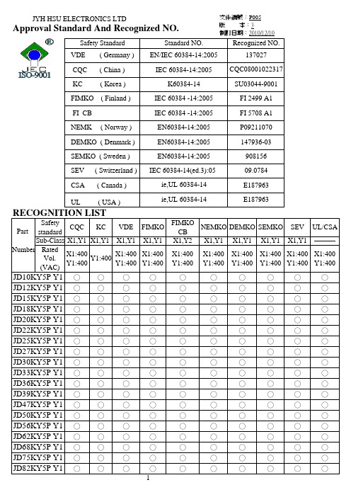
文件編號:P005
INTRODUCTION
版 本:3 制訂日期:2010/12/10
These Ceramic Disc Capacitors are specifically designed for AC applications and meet the
CQC ( China )
IEC 60384-14:2005 CQC08001022317
KC ( Korea )
K60384-14
SU03044-9001
VDE ( Germany ) EN/IEC 60384 -14:2005
137027
FIMKO ( Finland )
IEC 60384 -14:2005
X1
Y1
400 VAC
SEMKO, SEV, FIMKO,
400 VAC
400 VAC
NEMKO, DEMKO, VDE (0565 Teil 1-1)
Dielectric Rated Voltage Withstanding Voltage
Dissipation Y5P,Y5U
Test Voltage
10 pF to 4700 pF. measured at 1KHz±10%, 1.0 - 5.0 Vrms, 25℃
( C ) Tolerance
Insulation Resistance Temperature Typ) e Code
±10%
Y5P
±20%
Y5U,Y5V
( I R 10000 MΩ min, 500 VDC
(1) (2) (3) (4) (5)
(2) Rated capacitance
基尔斯特 5015a 电荷计用户手册说明书

Page 1/6Electronics & SoftwareCharge MeterUniversally Applicable for Piezoelectric Measuring Technology5015A _000-297e -01.21© 2010 ... 2021 Kistler Group, Eulachstrasse 22, 8408 Winterthur, Switzerland . Kistler Group products are This information corresponds to the current state of knowledge. Kistler reservesthe right to make technical changes. Liability for consequential damage resulting Type 5015A...This instrument can be used wherever mechanical quantities are measured with piezoelectric sensors. Piezoelectric sensors produce an electric charge which varies in direct proportion to the load acting on the sensor.• Single-channel charge amplifier • Piezotron input (option)• Measure-jump compensated• Liquid crystal display (128x128 pixels)• Menu-driven operation • Direct signal evaluation• Flexible adjustment of high-pass and low-pass filters • Compatible with Charge Amplifier Type 5011B...• PC-Software and Virtual Instrument Driver for LabVIEW DescriptionThe Type 5015A… is not only a charge amplifier but an uni-versal Charge Meter with a graphical liquid crystal display. However, the 19"-r ack module is also suitable for measurements in an industrial environment. It can display instantaneous, peak and average values as well as reference deviations. State-of-the art technology allows the naturally occurring interference to be almost entirely eliminated. The instrument is distinguished first-ly by its excellent technical data and secondly by its extremely simple operation.ApplicationThe instrument has been designed for use in research, devel-opment and the laboratory.OperationPage 2/65015A _000-297e -01.21© 2010 ... 2021 Kistler Group, Eulachstrasse 22, 8408 Winterthur, Switzerland Tel.+41522241111,****************,. Kistler Group products are This information corresponds to the current state of knowledge. Kistler reserves the right to make technical changes. Liability for consequential damage resulting Drift, meas. mode voltage DC (long) (@ Range 10 V FS; Gain = 1) at 25 °C, max. relative mV/s <±0,03 humidity RH of 60 % (non-condensing)at 50 °C, max. relative mV/s <±0,3 humidity RH of 50 % (non-condensing)Max. common mode voltage V <±30 between input and output ground Overload %F S ≈±105Piezotron mode Supply current mA 4 ±10 % Input voltage swing V 0 (20)Voltage Output Connector Type BNC neg.Output range FS V ±10/±5/±2,5/±2Output current mA <±2Output impedance Ω ≈10Measure-jump Compensated Measure-jump (Long) mV <±3 Correction time, inclusive reed-relay delay time ms <15 1)Zero errors mV <±2Output interference (0,1 Hz ... 1 MHz), Type 5015Axxx0 Range FS, LP filter off 2,000 ... 9,999 pC mVpp <140 ... <40 10,00 ... 99,99 pC mVpp <30 ... <10 1) 100,0 ... 999,9 pC mVpp <15 ... <7 1) ... mVpp <15 ... <7 1) 0,220 ... 2,200 µC mVpp <15 ... <7 1) Range FS, LP filter 30 kHz 2,000 ... 9,999 pC mVpp <60 ... <20 10,00 ... 99,99 pC mVpp <20 ... <7 1) ... mVpp <10 ... <5 1) 0,220 ... 2,200 µC mVpp <10 ... <5 1)Output interference (0,1 Hz ... 1 MHz), Type 5015Axxx1 Range FS, LP filter off 2,000 ... 9,999 pC, mV mVpp <220 ... <50 10,00 ... 99,99 pC, mV mVpp <50 ... <12 1) 100,0 ... 999,9 pC, mV mVpp <20 ... <7 1) ... mVpp <20 ... <7 1) 0,220 ... 2,200 µC mVpp <20 ... <7 1) Range FS, LP filter 30 kHz 2,000 ... 9,999 pC, mV mVpp <180 ... <50 1) 10,00 ... 99,99 pC, mV mVpp <30 ... <10 1) 100,0 ... 999,9 pC, mV mVpp <10 ... <5 1) ... mVpp <10 ... <5 1) 0,220 ... 2,200 µC mVpp <10 ... <5 1) 1)Values valid from MCC version V2.xxFrequency Response DC (Long), LP-filter off Bandwidth (–3 dB) kHz ≈0 ... 200 Group delay µs ≈10High-pass Filter (1st order)Analog high-pass filter DC (Long)Range FS Charge, (Voltage) 2 pC, (mV) s 10 000 1 000 pC, (mV) s 100 000Time constants Medium s 1/10/100/220 Short s 0,1/1/10/220Tolerance % <±20Digital high-pass filter computed by DSPTime constantsRange FS Charge, (Voltage) 2 pC, (mV) s 0,01/0,1/1 100 pC, (mV) s 0,01/0,1/1/10 ≥1 000 pC, (mV) s 0,01/0,1/1/10/100Tolerance % <±20Cutoff frequencies –3 dB Hz 16/1,6/0,16/0,016/ 0,0016 –10 % Hz 30/3/0,3/0,03/0,003 –5 % Hz 50/5/0,5/0,05/0,005 –1 % Hz 100/10/1/0,1/0,01Low-pass FilterDigital low-pass filter computed by DSP Filter Type IIR, linear phase Order 2. or 5.Cutoff frequency (–3 dB) Hz 5, 10, 20, 30, 50, 100, 200, 300, 500 kHz 1, 2, 3, 5, 10, 20, 22, 30, (LP off)Tolerance % <±10Page 3/65015A _000-297e -01.21© 2010 ... 2021 Kistler Group, Eulachstrasse 22, 8408 Winterthur, Switzerland Tel.+41522241111,****************,. Kistler Group products are This information corresponds to the current state of knowledge. Kistler reserves the right to make technical changes. Liability for consequential damage resulting Signal Evaluation Sample rates LP-filter on ksps 400 LP-filter offksps 1 000Minimum pulse width for peak-peak value detection LP-filter 5 Hz ... 30 Hz µs >2 500 LP-filter 50 Hz ... 300 Hz µs >250 LP-filter 500 Hz ... 3 kHz µs >25 LP-filter 5 kHz ... 30 kHz µs >2,5 LP-filter offµs >1Max. integration time for mean value min <75Integration time for the updating rate of the liquid crystal display Instant value ms 300 Characteristic values ms 300 Bar graph ms 17,5Remote Control Connector Type MiniDin round socked Pin allocationInputs with internal pull-up resistor Pin 4 (input) Window (remote) Pin 5 (input) Measure (remote) Pin 6 DGND Input voltagelogic inactive or input open V 3,5 ... 30 logic active V(mA) 0 ... 1 (0 ... 4)Delay timeWindow (remote) ms <0,5 Measure (remote) ms <15Digital Measuring Data TransferThe instrument provides a continuos measuring data transfer via the serial interface to a PC. For this the PC software (Windows) of the VI driver (LabVIEW) is required. This feature is not available on the IEEE-488 interface. Sampling rates ksps0,1/0,25/0,5RS-232C Interface (Electrically Separated)EIA-standard RS-232C Connector Type DB-9S (D-Sub)Pin allocation Pin 2 RxD Pin 3 TxD Pin 5 SG Max. cable length at 9 600 bps m <15 19 200 bps m <15 38 400 bps m <12 57 600 bps m <10 115 200 bps m <5Max. input voltage,continues V <±20Max. voltage between signal ground and protective ground V RMS <20Baud rates bps 1 200/9 600/ 19 200/38 400/ 57 600/115 200Data-bit 8Stop-bit 1Parity none SW handshake noneIEEE-488 Interface (Option)Standard IEEE-488.1-1987 Connector Type Microribbon series 57 (24-pole)Max. distance between devices m 2Max. bus length m 20Max. number of devices 15Adress range 0 ... 30Functions Listener and Talker Interface functions SH1, AH1, L4, LE0, T6, TE0, SR1, RL2, PP0,DC1, DT1, C0, E1Multiline commands DCL, SDC, GET, UNL, UNT, SPE, SPD Uniline commands IFC, REN, EOI, SRQ, ATNPage 4/65015A _000-297e -01.21© 2010 ... 2021 Kistler Group, Eulachstrasse 22, 8408 Winterthur, Switzerland Tel.+41522241111,****************,. Kistler Group products are This information corresponds to the current state of knowledge. Kistler reserves the right to make technical changes. Liability for consequential damage resultingPower Supply ConnectionPower plug (2P+E, protect. class I) IEC 320C14Supply voltage setable V~ 115/230Supply voltage tolerance % –22, +15Supply frequency Hz 48 ... 62Consumption VA ≈20Voltage between Signal ground and protective ground V RMS <50FusesF1 (slow) mA 100 F2 (slow) mA 100Remaining DataIP-Degree of protection IP40, IEC 60529Operating temperature °C 0 ... 50Storage temperature °C –10 (70)Rel. humidity, not condensing %10 (80)Vibration steadiness(20 Hz ... 2 kHz, duration 16 min, cycle 2 min.) g <10Shock steadiness (1 ms) g <200Housing dimensions with frame (wxhxd) mm 105,3x142x253,15 without frame (wxhxd) mm71,12x128,7x230Front panel (accordingDIN 41494, part 5/IEC 60297) HE/TE 3/14Weightkg ≈2,3Fig. 1: Block Diagram of charge meter Type 5015A…Page 5/65015A _000-297e -01.21© 2010 ... 2021 Kistler Group, Eulachstrasse 22, 8408 Winterthur, Switzerland Tel.+41522241111,****************,. Kistler Group products are This information corresponds to the current state of knowledge. Kistler reserves the right to make technical changes. Liability for consequential damage resultingFig. 2: Desktop Type 5015A1… (stackable)Fig. 3:19"-Rack plug-in Type 5015A0…Page 6/65015A _000-297e -01.21© 2010 ... 2021 Kistler Group, Eulachstrasse 22, 8408 Winterthur, Switzerland Tel.+41522241111,****************,. Kistler Group products are This information corresponds to the current state of knowledge. Kistler reserves the right to make technical changes. Liability for consequential damage resulting Included AccessoriesCharge Meter Type 5015A... with • Country-specific power cord • Plug for 'Remote Control'• Self-adhesive label with supply voltage details • Flash-Loader with current firmware• Demo-Program for visualization of the display on a PC • PC-Software and VI-Driver for LabVIEW for the equip-ment configuration and measured data acquisition • Instruction manual • Calibration sheetOptional Accessories Type/Art. No.• RS-232C cable, l = 5 m, null-modem, 1200A27 DB-9P/DB-9S• or PC-link cable RS-232C, l = 3 m, 1465A3 DB-25P/DB-9S• with suitable D-Sub adapter , 1479 DB-9P/DB-25SInstrument ConfigurationsThe complete type designation of the Charge Meter is made up of the basic type designation Type 5015A... and four ad-ditional digits.The basic type contains a single-channel Charge Meter (with charge input for piezoelectric sensors) with display unit and RS-232C interface in the following versions:Ordering Key Type 5015ASize/Measuring Range19" rack module version according to 0 DIN 41494; width 14 TE and height 3 HE Desktop version with support bracket 1Without interface option0With IEEE-488 interface (option) 1Adjusted in the factory to 230 V~; 0switching to 115 V~supply by the user possible at any time Adjusted in the factory to 115 V~; 1switching to 115 V~supply by the user possible at any time Without voltage input0With voltage input for sensors with 1integrated Piezotron circuitry (option)Windows is a registered trademark of Microsoft bVIEW is a registered trademark of National Instruments Corporation.。
微量铜-铁对硅片表面污染的初步分析

第26卷 第5期2005年5月 半 导 体 学 报CHIN ESE J OURNAL OF SEMICONDUCTORSVol.26 No.5 May ,20053国家自然科学基金资助项目(批准号:20073036) 郑 宣 男,1980年出生,硕士研究生,研究方向为电化学,主要从事半导体硅片的金属微观污染机理研究. 通信联系人.Email :xcheng @ 2004205216收到,2004207228定稿ν2005中国电子学会微量铜2铁对硅片表面污染的初步分析3郑 宣 程 璇(厦门大学化学系固体表面物理化学国家重点实验室,厦门 361005)摘要:通过比较微量铜铁单独存在和共存时对p 2型硅片表面的污染,采用电化学直流极化和交流阻抗技术以及SEM 、EDX 和A ES 等现代表面分析技术,对未污染和受污染的硅片表面进行了初步的研究.结果表明,当氢氟酸溶液中同时含有ppb 2水平(10-9)的铜铁杂质时,不但铜会沉积在硅片表面上发生铜污染,而且还导致硅片表面的碳污染,并从电化学极化电阻、元素深度分布和空间电荷效应等方面对硅片表面铜与碳污染进行了初步的分析和讨论.关键词:硅片清洗;金属污染;铜沉积;碳污染PACC :7340M ;8245 EEACC :2550E中图分类号:TN30512 文献标识码:A 文章编号:025324177(2005)05209702071 引言随着集成电路由大规模向超大规模(VL SI )和甚大规模(UL SI )发展,电路的集成度日益提高,污染物对器件的影响也愈加突出,以致于洁净表面的准备技术已成为制作64和256兆字节DRAM 的关键技术.湿法化学清洗是当今IC 制造工艺中使用最为频繁的步骤,主要包括硅氧化物/氮化物刻蚀、硅片清洗和化学机械抛光等,在亚微米硅器件的制造中尤为重要.随着最小特征尺寸的不断减小,即所谓的单元图形的尺寸日益微化,对半导体硅表面清洁度的要求也愈来愈苛刻,提出了“超洁净硅表面”的要求[1].因而,硅片清洗工艺是否有效将直接影响器件的性能和可靠性,每一步清洗过程都可能对硅片造成污染,从而导致缺陷形成和器件失效.硅片表面的污染物通常以原子、离子、分子、粒子或膜的形式通过化学或物理吸附的方式存在于硅片的表面或氧化膜中.原子型杂质主要是指重、贵金属原子(如Cu 、Ag 、Au 、Pt 等),它们主要来自于硅的酸性刻蚀剂如氢氟酸溶液中,通过电化学还原方式沉积到硅片表面.原子型杂质主要影响器件中的少子寿命、表面的导电性、氧化物的完整性和其他器件稳定性参数,是造成器件失效的主要原因.特别是在高温或电场下,它们能够向半导体的本体内扩散或在表面扩大分布,导致器件性能下降,产率降低.迄今为止,人们对硅片表面金属污染机理的研究主要集中在对铜沉积的研究[2~10],只有少量的研究工作涉及银、铂等贵金属和铁、镍、铬、锌等过渡金属[11~13].一般认为铜离子从氢氟酸溶液中通过电化学反应沉积在硅表面,同时硅表面发生溶解反应和氢气析出反应:Si +6HF →H 2Si F 6+4H ++4e -(1)2H ++2e -→H 2(2)Cu 2++2e -→Cu 0(3)通过交流阻抗和直流极化电化学技术[2~4]证实了铜在硅表面上的沉积是电化学属性,腐蚀电流密度和开路电位对pp b 水平(10-9)的铜污染很敏感.通过考查光照和硅片类型对铜沉积行为的影响,J eon [2]和Cheng 等人[3,4]还发现铜在p 2型硅表面上的沉积比在n 2型硅表面上的沉积严重,添加非离子型表面活性剂以及黑暗条件可以大大减少铜在两种硅表面第5期郑 宣等: 微量铜2铁对硅片表面污染的初步分析的污染.另外,硅片与污染金属之间的电负性差异以及各金属氧化物的生成焓的大小也会影响金属沉积行为和反应动力学[1].在最初的60s中铜的沉积为成核控制,之后转化为扩散控制.铜沉积通过静态扩散层受Cu2+扩散的限制,在沉积的初期,成核过程对铜颗粒的生长起主导地位[14].有人根据铜沉积导致硅表面产生小孔现象提出了金属诱导孔蚀(M IP)机理[15].这种类似腐蚀机理模型虽然可以较好地解释具有比硅更高标准还原电位的金属(如Cu,Ag, Pt等)可以优先沉积在硅表面,但是缺乏直接的电化学反应根据.Norga等人[16]试图从光电化学角度提出用能带模型来阐明掺杂类型、光照水平和硅电极上电位与铜沉积速度之间的关系.在硅片制造及加工过程中,除了铜污染外,铁的污染也是很严重的.据检测,在离子注入等加工过程中,铁的含量约为1012~1013atom/cm2.尽管铁的还原电位比硅低,理论上铁不可能象铜那样以氧化还原的方式沉积在硅表面,但铁的氧化物(Fe2O3)生成焓(-822kJ/mol)比硅的氧化物(SiO2)生成焓(-909kJ/mol)大,所以铁很可能以氧化物的形式吸附在SiO2膜中.硅片表面清洗过程中往往同时含有多种金属杂质,因此对氢氟酸(湿法化学清洗中最常用的化学试剂)中同时含有多种微量金属离子时硅片表面的污染行为进行系统的研究,对控制和消除硅表面的金属微观污染,促进亚微米和纳米电子器件的发展具有重要的指导意义.目前对多种不同金属共存条件下硅片表面金属污染行为的研究尚不多见.最近, Cheng等人[13]通过比较Cu和Ag单独存在和Cu2 Ag共存时的金属沉积行为发现,铜银共存时,硅表面的铜、银沉积速度比铜、银单独存在时的沉积速度快,从而加剧了硅表面的金属污染,且同时沉积在硅表面的铜、银晶粒会形成金属原子簇,导致硅片表面微观粗糙度变大.本文报道了Cu2Fe体系的初步研究结果.首先通过电化学直流极化和交流阻抗技术得到了金属在硅片表面的电化学响应,然后采用扫描电子显微镜(SEM)和能量散射X射线能谱(EDX)技术表征了污染前后硅的表面形貌,并对硅表面的化学组分进行了半定量的分析.此外,还利用俄歇电子能谱(A ES)对污染前后硅片表面进行了元素深度剖析,从而获得Cu/Si界面层的纵向元素分布信息.最后,根据以上实验结果分析和讨论了氢氟酸溶液中微量铜单独存在和铜-铁共存时对硅表面产生的碳和铜污染的异同点.2 实验硅片样品是从江苏无锡华晶电子集团硅材料厂购买的100mm圆形单晶硅片.晶向为p(100),电阻率为1~5Ω・cm.实验时将100mm圆形单晶硅片切割成1125cm×1125cm的方形硅片.电解槽用聚四氟乙烯作为材料,采用三电极系统,工作电极为p (100)硅片,辅助电极为铂片,参考电极为饱和甘汞电极(SCE).电解质溶液是用电子纯的40%氢氟酸(HF)和超纯水(18MΩ・cm)按体积比1∶50配制而成.金属离子浓度为1000pp m的标准Cu,Fe离子溶液(硝酸为溶剂),由厦门大学分析化学教研室提供,实验时利用微量注射器加入所需浓度的金属溶液.实验前将硅片放入H2SO4∶H2O2=4∶1(体积比)的清洗液中室温浸泡10min,然后用超纯水清洗三遍.再置于1∶50(体积比)的H F酸溶液中浸泡10s.最后用超纯水清洗三遍.电化学测试采用美国EG&G公司生产的恒电位/两相锁相分析仪,直流极化测试的扫描速度为1mV/s,交流阻抗测试的频率为105~10-2Hz.采用德国L EO21530场发射扫描电子显微镜系统对硅片表面进行形貌观察,电子源为Shott ky场发射电子枪,激发电位为20keV.硅片表面化学组分通过该仪器所附带的英国牛津EDS7426能谱检测仪进行能量散射X射线能谱(EDX)分析,收集时间为50s,能量范围为0~20keV.硅片表面均未镀膜.硅片表面元素深度分布是通过美国物理电子公司的P HI660扫描探针显微系统获得,激发电压为5keV,电流为10nA,溅射速率为18nm/min,分析的元素包括C,Cu,Fe,F,O,Si等.3 结果与讨论311 铜沉积的电化学行为图1和图2分别给出了污染前后硅电极在氢氟酸溶液中的极化曲线和交流阻抗谱图.从图1中可以看出,在氢氟酸溶液中加入微量的铜和铜2铁混和溶液后,其开路电位(即图1中阴、阳两支极化曲线179半 导 体 学 报第26卷的交汇电位)均向电位正偏压的方向移动,且单独加铜时的开路电位比铜2铁共存时的高.图2也表明,污染后的Nyquist 图中的半圆比污染前的小,说明阻抗值发生了明显的变化.通过分别拟合Tafel和图1 光照条件下污染前后硅电极的Tafel 极化曲线 金属浓度:500ppbFig.1 Tafel curves obtained before and after metallic contamination under illuminated condition (metallic con 2centration :500ppb)图2 光照条件下污染前后硅电极的交流阻抗谱图 金属浓度:500ppb.Fig.2 Impedance spectra obtained before and after metallic contamination under illuminated condition (a )Nyquist plot ;(b )Bode plot (metallic concentration :500ppb )阻抗结果,可以得到极化电阻的大小,其结果如表1所示.极化电阻(R p )是表征固/液界面电化学反应快慢的重要参数之一,其大小与发生在界面上的电化学反应速度成反比.由表1可知,虽然两种方法得到的R p 值并不完全相同,但其变化趋势却是一致的,即当硅片表面受到金属污染时,其R p 值迅速减小,这表明硅/氢氟酸界面上的电化学反应被加速.铜对硅片单独污染时,造成阴极反应的Tafel 斜率变陡(图1中下半支曲线),阻抗图上的半圆明显缩小并出现两个半圆(图2(a )),表明铜直接从溶液中沉积到硅表面(反应式(3)),且铜的沉积加速氢气的析出(反应式(2)),最终加快反应式(1),并导致硅表面微粗糙度增加[3].当同样浓度的铜和铁同时加入溶液中,与铜单独污染行为相比,其阴极反应的Tafel 斜率几乎没有变化(图1),但R p 值减小,阻抗图上的半圆仍然变小(图2),R p 值也有所减少,但变化不大,铜2铁共存时的电化学行为变化没有铜单独污染时的显著,其原因将在后面的讨论中给出.表1 通过电化学实验结果计算的极化电阻值Table 1 Polarization resistance calculated f rom electro 2chemical measurementsContaminant in HF/ppbPolarization resistance (R p )/k ΩCu Fe Tafel slope Impedance spectrum0027.216.55000 2.8 4.95005001.92.7312 硅表面的形貌和化学组分图3比较了p 2型硅受铜污染或铜2铁污染前后以及经不同时间污染后的硅片表面形貌.显然,没有受污染的硅表面洁净平整(图3(a )),当受到微量的铜单独污染后,硅表面出现大小不一的铜金属微晶粒(图3(b )),随着铜污染的时间从10min 延长到30min ,硅表面变得非常粗糙,且铜颗粒明显长大,并出现团聚现象(图3(c )).当硅片同时受到微量的铜和铁污染时,在浸泡时间为10min 的条件下,与同样浓度的铜单独污染相比(图3(b )),可以看出硅表面变得更加粗糙,铜在硅表面上的存在形式发生了显著的变化,铜颗粒更加紧密地结合在一起(图3(d )).在浸泡时间为30min 的条件下,铜2铁共同污染和铜单独污染导致的硅表面形貌基本相似,只是铜在硅表面的覆盖层变得更致密,并出现了孔洞(图3(e )).金属诱导孔蚀(metal induced pitting )机理可279第5期郑 宣等: 微量铜2铁对硅片表面污染的初步分析以较好地解释铜沉积导致硅表面出现孔洞的现象[15].也有研究者认为Fe3+的存在极易代替n2型硅上SiO x/SiO2的Si4+从而形成带负电的[FeO2 Si]-,产生交流表面光电压(ac2SPV),进而影响硅的表面性质[17].我们猜测当铜2铁共存时,铁离子可能通过改变硅表面上的电荷从而使得铜与硅基体的作用增强,导致硅表面粗糙度增加,但对铜在硅表面的沉积速度并没有太大的影响(其极化电阻影响不大).这一点也可以通过下面的能谱分析其化学组分得到证实.图3 硅片表面形貌图 (a)无污染;(b)500ppb Cu,10min;(c)500ppb Cu,30min;(d)500ppb Cu和500ppb Fe,10min;(e)500ppb Cu和500ppb Fe,30minFig.3 Surface morphologies of silicon wafer (a)Without contamination and contaminated;(b)500ppb Cu for10min;(c)500ppb Cu for30min;(d)500ppb Cu and500ppb Fe,10min;(e)500ppb Cu and500ppb Fe, 30min 表2给出了通过EDX分析得到的受铜单独污染和铜2铁共同污染后硅片表面的化学元素原子百分数.表2显示,铜单独存在时,污染时间的增加导致铜在硅表面上的原子百分比增加,即铜在硅片表面的沉积量增大.同时,硅片经过较长时间的污染,表面出现明显的碳污染(比较样品1和2).铜2铁共存时,污染10min后铜在硅片表面的沉积量已经超过铜单独存在污染30min时的沉积量,碳污染也显著加剧(比较样品1和3).然而,随着铜2铁污染的时间增加到30min,铜在硅片表面的沉积量却有所降低,而碳污染仍在增加(比较样品3和4),这与同样污染时间下铜单独存在时的硅片相比,铜2铁共同污染导致硅片表面铜沉积量并未增加且有所减少,但碳的吸附量却从18174%增加到36168%,几乎翻倍(比较样品2和4).可见,铁的存在导致碳在硅片表面的吸附加剧,而铜原子百分数略有减少.由于硅片表面上的铜沉积主要发生在最初的几十秒,因此,碳的吸附很有可能发生在硅/铜界面.同时,我们猜测铁离子吸附在硅表面会改变硅表面的带电状态,所形成的双电层将使表面处的电子密度减少,这种减少会降低Cu2+吸附的速率以及吸附能,从而改变铜离子的还原动力.碳在硅表面的吸附量的变化很有可能与此有关.表2 EDX分析结果Table2 Atomic percentage of surface compositions ob2 tained f rom EDXSample Test conditionContaminant/ppb Atomic percent/%Cu Fe Si C Cu 1Illuminated,10min500096.8 3.2 2Illuminated,30min500070.0518.7410.68 3Illuminated,10min50050058.9926.1514.86 4Illuminated,30min50050055.1136.688.21为了考察硅/铜界面各元素的纵向分布情况,得到界面结构信息,利用俄歇电子能谱对经过铜单独污染和铜2铁共同污染30min的硅片表面进行了元素深度剖析.为便于比较,还对未污染的硅片(只进行了清洗步骤)进行了分析,结果如图4所示.图5特别比较了未污染和受到铜或铜-铁共同污染的硅片表面碳、铜和硅元素随深度变化的分布情况.379半 导 体 学 报第26卷图4 硅片表面元素深度剖析图 (a)空白样品(无污染);(b)500ppb Cu污染,30min;(c)500ppb Cu和500ppb Fe污染,30min.Fig.4 Depth profiles of elements f rom silicon wafer surface (a)Clean;(b)500ppb Cu,30min;(c)500ppb Cuand500ppb Fe ,30min.图5 硅片表面元素深度分析比较图 (a)碳;(b)铜;(c)硅Fig.5 A comparison in depth profiles of elements f rom silicon wafer surface (a)C;(b)Cu;(c)Si 从硅片表面的元素深度剖析图可知,三块硅样品的表面都有明显的碳吸附,虽然碳的强度都呈现从表面到本体急剧下降的趋势,但吸附发生的程度和变化规律却与硅片表面的污染状态密切相关.对于未受铜、铁污染的硅样品(图4(a)和图5(a)),其表面(20~30nm)碳吸附程度较轻微.而受铜单独污染的硅片其表面碳含量随深度变化先显著减小,然后在100~200nm处出现峰值,最后基本维持不变(图4(b)和图5(a)).值得注意的是,碳层的最高点几乎和Si/Cu界面的位置(约是Cu含量下降为50~80%的位置)相同.可以推断在Si/Cu的界面上碳的吸附是很强的,这也证实了在Si/Cu界面上由于空间电荷形成双电层对碳的吸附有很大的影响.图5(a)还显示,碳在三种硅片表面的含量随深度增加而减小,但最后并没有降到零(甚至到500nm处还能检测到碳),这可能是吸附在硅表面的CO或CO2通过Ar+的溅射轰击而内迁所致[19].铜2铁共存时硅片表面的碳污染明显加剧,且碳含量也随深度变化显著减小,但降低的幅度较铜单独污染时的小且没有出现峰值(图4(c)和图5(a)).由于Fe3+作为表面态,可以接受电子,而且有计算显示对于3×10-4单层Fe3+转变为Fe2+足以使表面势垒由零改变到0142eV[18].所以Fe3+在Si表面的存在会影响表面势垒,从而对铜的还原反应产生影响.因此,铁的存在可能导致空气中的碳(如CO,C x H y,C H4等)更容易吸附在硅的表面.对于铜污染而言(图5(b)),很显然在受到铜单独污染的硅片表面铜的沉积速度较快,铜含量先随深度变化迅速增加,在20~80nm处出现峰值(Cu 沉积层),随后铜的含量有一个缓慢下降的趋势,最后趋于平稳.铁的加入并未加剧铜沉积.因此,铜2铁共存时,铜沉积厚度要小得多(峰值出现在20~30nm处).比较硅表面含量随深度变化(图5(c))可看出,受铜单独污染的硅表面含量有所减少,但仅发生在离开表面20~30nm处,可能是由于碳吸附所致,而受到铜2铁共同污染的硅表面含量却随深度增加而显著降低,在160nm处达到最小,然后才有所回升,但并没有恢复到最初值.这再次证实硅表面在只有铜污染的情况下由于铜沉积(反应式(3))加速了硅的刻蚀溶解(反应式(1))和氢气的析出(反应式(2))[2,3],从而导致硅表面粗糙度增加.当铜2铁共存时,由于Fe3+在硅表面的吸附会出现高密度的表面479第5期郑 宣等: 微量铜2铁对硅片表面污染的初步分析态,从而减缓铜在硅表面的沉积速度,更多地影响已经沉积在硅上的铜与硅基体之间的相互作用,加剧铜的生长和碳的吸附,导致硅表面粗糙度增加,并出现孔洞(图3).4 结论对于单铜体系,随着污染时间的增长,铜在硅片表面的沉积也增加,导致硅片表面微观粗糙度增加.铜2铁共存时,铜在硅上的沉积形貌发生了很大变化,而且随着污染时间的增长,铜在硅表面会继续生长,铜颗粒会结合得更紧密,并形成孔洞,出现类似金属诱导孔蚀现象,同时在硅/碳界面产生碳污染.碳在硅片表面上的吸附与Fe3+的存在密切相关,铁的存在可能导致空气中的碳(CO,C x H y,C H4等)更容易吸附在硅的表面.参考文献[1] Ohmi T,Imaoka T,Sugiyama I,et al.Metallic impurities seg2regation at t he interface between Si wafer and liquid duringwet cleaning.J Electrochem Soc,1992,139:3317[2] J eon J S,Raghaavan S,Parks H G,et al.Electrochemical in2vestigation of copper contamination on silicon wafers from HFsolutions.J Electrochem Soc,1996,143:2870[3] Cheng X,Li G,Kneer E A.Electrochemical impedance spec2troscopy of copper deposition on silicon from dilute hydroflu2 oric acid solution.J Electrochem Soc,1998,145:352[4] Cheng Xuan,Lin Changjian.Electrochemical investigations ofp2n junction and copper deposition on semiconductor siliconwafers.Chinese Journal of Semiconductors,2000,21(5):509(in Chinese)[程璇,林昌健.半导体硅片的p2n结和铜沉积行为的电化学研究.半导体学报,2000,21(5):509][5] Perterson C A,Bermeire B,Sarid D,et al.Reduction of surfaceroughening due to copper contamination prior to ultra2t hingate oxidation.Appl Surf Sci,2001,181:28[6] Lin P S D,Marcus R B,Sheng T T,et al.Leakage and break2down in t hin oxide capacitors2correlation wit h decorated stac2king fault s.J Electrochem Soc,1983,130:1878[7] Zhong L,Shimura F.Dependence of lifetime on surface con2centration of copper and iron in silicon wafers.Appl PhysLett,1992,61:1078[8] Takizawa R,Nakanishi T,Ohsawa A.Degradeation of metal2oxide2semiconductor devices caused by iron impurities on t hesilicon wafer surface.J Appl Phys,1987,62:4933[9] Tsuneo A,Mayumi S,Yasuo M.Issues of wet cleaning in UL2SI process.IEICE Trans Electron,1996,E792C:337[10] Yamada T,Mat suo M,K ohno H,et al.Sensitive detection oftrace copper contamination on a silicon wafer by total reflec2tion X2ray fluorescence using W2Lβor Au2Lβexcitationsource.Spectrochimica Acta Part B:Atomic Spect roscopy,2001,56:2307[11] Torcheux L,Mayeux A,Chemla M.Electrochemical couplingeffect s on t he corrosion of silicon samples HF solutions.JElectrochem Soc,1995,142:2037[12] Mouche L,Tardif F,Derrien J.Mechanisms of metallic impu2rity deposition on silicon substrates dipped in cleaning solu2tion.J Electrochem Soc,1995,142:2395[13] Cheng X,Gu Chi,Feng Zude.Microcontamination of siliconwafer surfaces by copper and silver.J Elect rochem Soc,2003,150:G112[14] Oliver M R Chyan,Chen J J,Hsu Y C.Copper deposition onHF etched silicon surfaces:morphological and kinetic studies.J Electrochem Soc,1996,143:92[15] Morinaga H,Suyama M,Ohmi T.Mechanism of metallic par2ticle growt h and metal2induced pitting on Si wafer surface inwet chemical processing.J Electrochem Soc,1994,141:2834 [16] Norga G J,Platero M,Black K A.Mechanism of copper depo2sition on silicon from dilute hydrofluoric acid solution.J Elec2trochem Soc,1997,144:2801[17] Shimizu H.Atomic bridging and barrier2type AC surface pho2tovoltage measurement s on iron2and2copper2contaminated sili2 con surfaces.J Electrochem Soc,2003,150:725[18] Lu T C,Huang N K,Lin L B,et al.XPS and A ES investiga2tion of two2layer Ti2O film on silicon substrate.Nuclear Tech2niques,1996,19:332[19] Norrison S R.Surface Chemical Physics.Beijing:Peking Uni2versity Press,1984:49(in Chinese)[Norrison S R.表面化学物理.北京:北京大学出版社,1984:49]579半 导 体 学 报第26卷679A Preliminary Analysis on Surface Contamination ofSilicon W afer by Cu and FeZheng Xuan and Cheng Xuan(S tate Key L aboratory f or Physical Chemist ry of S oli d S urf aces,Depart ment of Chemist ry,X iamen Universit y,X iamen 361005,China)Abstract:Through a comparison of surface contamination of p2type silicon wafer by trace amounts of copper and iron when they are present in solutions separately or simultaneously,a preliminary study is conducted to investigate the non2contaminated or contaminated silicon wafer by employing electrochemical DC polarization and AC impedance techniques,as well as modern sur2 face analysis technologies including SEM,EDX,and A ES.It is revealed that in hydrofluoric acid solutions containing both ppb2 level of copper and iron,not only would copper deposition take place,but also could carbon contamination occur at the wafer surface.G eneral analysis and discussion in copper and carbon contamination are provided based on the polarization resistance,el2 emental depth distribution,and space charge effect.K ey w ords:wafer cleaning;metallic contamination;copper deposition;carbon contaminationPACC:7340M;8245 EEACC:2550EArticle ID:025324177(2005)05209702073Project supported by National Natural Science Foundation of China(No.200273036) Zheng Xuan male,was born in1980,master candidate.He is engaged in t he research on metallic micro2cantamination on silicon wafer.Email:xcheng@ Received16May2004,revised manuscript received28J uly2004ν2005Chinese Institute of Electronics。
汽车检测故障码大全

汽车检测故障码大全00000没有查询到任何故障00001制动器控制单元00002变速器控制单元00003控制单元00224碟型天线需要重新校准00237ABS电磁阀:左前(N59)00238ABS电磁阀:右前(N58)00239ABS电磁阀:左后(N57)00240ABS电磁阀:右后(N56)00241驱动防滑压力调节阀(N238)00242发动机节气门阀(N237)00243发动机制动器00244ABS阀供应电压:右前+左后00245ABS阀供应电压:左前+右后00246ABS阀接地:右前+左后00247ABS阀接地:左前+右后00248变速器开关(E206)00250分动器开关(E207)00254驱动防滑调节错误00255ABS电磁阀00257ABS进油阀:左前(N101) 00258电磁阀1:(N88)00259ABS进油阀:右前(N99)00260电磁阀2:(N89)00261进油阀:ABS后部(N103)00262电磁阀3:(N90)00263变速器00264电磁阀4:(N91)00265ABS出油阀:左前(N102)00266电磁阀5:(N92)00267ABS出油阀:右前(N100)00268电磁阀6:(N93)00269ABS出油阀:后部(N104)00270电磁阀7:(N94)00271参见维修组100273ABS进油阀:右后(N133)00274ABS进油阀:左后(N134)00275ABS出油阀:右后(N135)00276ABS出油阀:左后(N136)00277ABS进油阀/出油阀:左前(N137)00278ABS主阀:(N105)00279差速锁阀-1-:(N125)00280差速锁阀-2-:(N126)00281车速传感器(G68)00282节气门位置调节器(V60)00283ABS转速传感器:左前(G47)00284ABS进油阀/出油阀:右前(N138)00285ABS转速传感器:右前(G45)00286ABS进油阀/出油阀:左后(N139)00287ABS转速传感器:右前(G44)00289ABS进油阀/出油阀:右后(N140)00290ABS转速传感器:右前(G46)00291ABS压力警报开关/液面报警开关(F116/F117)00292液压供应压力油位00293多功能开关(F125)00294变速器压力状态开关1(F174)00295变速器压力状态开关2(F175)00296强制低档开关(F8)00297变速器转速传感器(G38)00298后桥差速锁开关(E121)00299变速器换档X围程序开关(E122)00300变速器油温度传感器(G93)00301ABS回流泵(V39)00302ABS电磁阀继电器(J106)00303功能选择器开关(E91)00305燃油消耗指示信号00306二次空气喷射缸体左侧00307二次空气喷射缸体右侧00309洗涤液计量泵(V135)00310催化转换器温度传感器1(G20)00312催化转换器温度传感器2(G132)00313催化转换器00314废气内部循环双路阀(N161)00347电磁阀800348电磁阀900349电磁阀1000350Mass Recirc.Modulation Valve00351中间轴转速传感器(G265)00369EPC继电器负荷00438燃料供应传感器2(G169)00439燃料供应传感器3(G237)00440燃料供应传感器辅助油箱(G292)00441燃料供应传感器辅助油箱(G293)00442燃油泵接线柱87F00443燃油泵保险丝:辅助油箱(S266)00444燃油泵控制:辅助油箱00445Pump for Haldex-Coupling(V181) 00446Precharge Pump ON00447Precharge Pump OFF00448AWD全轮驱动离合器接合00449AWD全轮驱动离合器别离00450发动机过热导致功能限制00454AWD全轮驱动监控器00455控制单元:存取和开场控制:舒适系统CAN(J518)00456控制单元:存取和开场控制(J518)00457控制单元:网络接口(J519)00458控制单元:电瓶监控(J367)00459控制单元:显示和输入:前(J523)00460控制单元:显示和输入:后(J524)00461控制单元:坐椅存储器:乘客侧(J521)00462控制单元:坐椅存储器:后部(J522)00463控制单元:DSP(J525)00464控制单元:收音机/导航系统显示(J503)00465控制单元:/通讯(J526)00466控制单元:转向电器(J527)00467TV调谐器(R78)00468CD-ROM驱动器(R92)00469显示数据总线00470舒适系统数据总线00471控制单元:Elect.Regulated Dampers(J250)00472控制单元:制动助力(J539)00473控制单元:电子制动/手制动(J540)00474控制单元:电子防盗器00475控制单元:滑动车门00476控制单元:燃油泵(J538)00477控制单元:显示和输入:舒适系统CAN:前(J523)00478控制单元:显示和输入:舒适系统CAN:后(J524)00479控制单元:遥控/中央门锁(J276)00480控制单元:仪表板信息系统CAN(J285)00496车身自调平传感器:前部00497车身自调平传感器:后部00498[Fahrschreiber][Translation N/A]00499电瓶电压指示灯(Y11)00500机油温度指示灯(Y12)00501机油状态指示灯(K38)00502防盗器指示灯(K115)00503Control/Drive for Pump-Jet Valves00504喷射阀:缸1(N240)00505喷射阀:缸2(N241)00506喷射阀:缸3(N242)00507喷射阀:缸4(N243)00508喷射阀:缸5(N244)00509喷射阀:缸6(N245)00512凸轮轴位置传感器参考标记错误00513发动机转速传感器(G28) 00514曲轴位置传感器(G4)00515凸轮轴位置传感器(G40)00516节气门怠速位置开关(F60)00517节气门全负荷位置开关(F81)00518节气门位置传感器(G69)00519进气压力传感器(G71)00520空气质量/流量传感器(G70/G19)00521CO电位计(G74)00522发动机冷却液温度传感器(G62)00523进气温度传感器(G42)00524爆震传感器1(G61)00525氧传感器(G39)00526刹车灯开关(F)00527进气温度传感器(G42/G72)00528大气压力/海拔高度传感器(F96)00529发动机转速信号丧失00530节气门调节器位置传感器(G88) 00531空气流量计参考电压00532供应电压B+00533超过怠速调节自适应限制(N71)00534机油温度传感器00535第一个爆震传感器调节00536第二个爆震传感器调节00537氧传感器调节00538参考电压00539燃油温度传感器-1-(G81)00540爆震传感器200541滑阀开度传感器(G99)00542针阀行程传感器(G80)00543超过最大的发动机转速00544超过最大的增加压力00545发动机与变速器的电气连接00546数据线路故障00547ABS压力控制开关(F137)00548蓄电池正极供应:DTC存储器00549消耗信号00550喷射开场控制/喷射初始点调节00551催化转换器温度过热00552空气流量计位置传感器(G19) 00553空气流量计传感器(G70)00554氧传感器控制200555氧传感器2(G108)00556EGR废气在循环系统电位计(G212)00557动力转向压力开关(F88)00558混和气控制界限:稀00559混和气控制界限:浓00560废气内部循环系统00561燃料混合比调节00562机油油位温度传感器00563燃油消耗指示灯00565全自动空调显示/控制:后部(E265)00566辅助转向00567转向控制00568动力转向电机位置传感器00569动力转向电机电流00570动力转向电机继电器(J509)00571动力转向离合器00572动力转向位置传感器(G268)00573动力转向压力传感器(G269)00574驱动电机On00575进气歧管压力00576接线柱1500577爆震传感器控制:1缸00578爆震传感器控制:2缸00579爆震传感器控制:3缸00580爆震传感器控制:4缸00581爆震传感器控制:5缸00582爆震传感器控制:6缸00583爆震传感器控制:7缸00584爆震传感器控制:8缸00585废气内部循环温度传感器(G98)00586废气内部循环系统控制00587混合器控制的调节极限00588平安气囊点火期:驾驶员侧(N95)00589平安气囊点火器:乘客侧(N131)00590平安气囊点火器:乘客侧(N132)00591平安带开关:左侧(E24)00592平安带开关:右侧(E25)00593座椅连接开关:乘客侧00594平安气囊点火电路00595碰撞数据已经存储00596喷油器之间连线短路00597车轮转速信号偏差00598液压或者机械故障00599压力开关/制动灯开关工作正常?00600温度调节翻板电位计(G92)in(V68)00601中央翻板电位计(G112)in(V70)00602脚坑/除霜翻板电位计(G114)in(V85)00603脚坑/除霜翻板电机(V85)00604通风翻板电位计(G113)in(V71)00605新鲜空气/循环空气翻板双向阀(N63)00606发动机冷却液真空双向阀(N147)00607外部温度显示(G106)00608负荷传感器(G119)00609点火放大器输出100610点火放大器输出200611点火放大器输出300612点火放大器输出400613点火放大器输出500614点火放大器输出600615点火放大器输出700616点火放大器输出800617平安气囊减速度传感器:左侧(G104)00618平安气囊减速度传感器:右侧(G105)00619传感器导线:左侧00620传感器导线:右侧00621减压阀(N155) 00622燃油滤清器放水00623ABS/变速器电气连接00624A/C压缩机接通00625车辆速度信号00626预热时间指示灯(K29)00627水位传感器(G120)00628执行参数监控00629GRA/柴油喷射装置制动踏板开关(F47)00630空调开关已经翻开00631AC<->Motronic通讯连接00632全自动空调接口00633点火/传感器滞后线路00634EDS电子差速锁串联电阻(N159) 00635氧传感器加热器:催化转换器之前00636加速度传感器:右前(G121) 00637加速度传感器:左后(G122)00638发动机与变速器电气连结200639减速度传感器(G123)00640氧传感器加热器继电器(J278)00641ATF温度00642EDS转换阀:右前(N166)00643EDS出油阀:右前(N167)00644EDS转换阀:左前(N168)00645EDS出油阀:左前(N169)00646ABS-ASR/发动机电气连结100647ABS-ASR/发动机电气连结200648氧传感器加热器:催化转换器之后00649ABS进油阀/出油阀:后(N160) 00650离合器踏板开关(F36)00651点火线路导线00652档位监控/换档X围控制器00653自动变速器选档杆位置正确?00654平安带涨紧触发器:左侧(N153)00655平安带涨紧触发器:右侧(N154)00656平安气囊坐椅占用传感器(G128)00657中央出风口调节电机(V102)00658操作控制单元00659自身测试装置00660强制低档开关/节气门位置传感器00661温度指示灯00662转速表(G5)00663车速表(G21)00664燃油表00665平安带警告灯(K19)00666钟/蜂鸣器/锣00667外部温度信号00668供电电压接线柱3000669第二个发动机故障指示灯(K97)00670节气门位置传感器(G127)00671巡航控制开关(E45)00672带有串联电阻的ABS液压泵00673踩下刹车踏板00674松开刹车踏板00675左前进油阀:0V左前出油阀:0V左前车轮:已抱死00676左前进油阀:VBatt左前出油阀:0V左前车轮:已抱死00677左前进油阀:VBatt左前出油阀:VBatt左前车轮:已释放00678左前进油阀:VBatt左前出油阀:0V左前车轮:已释放00679第二个氧传感器加热器:催化转换器之前00680右前进油阀:0V右前出油阀:0V右前车轮:已抱死00681右前进油阀:VBatt右前出油阀:0V右前车轮:已抱死00682右前进油阀:VBatt右前出油阀:VBatt右前车轮:已释放00683右前进油阀:VBatt右前出油阀:0V右前车轮:已释放00684第二个氧传感器加热器:催化转换器之后00685左后进油阀:0V左后出油阀:0V左后车轮:已抱死00686左后进油阀:VBatt左后出油阀:0V左后车轮:已抱死00687左后进油阀:VBatt左后出油阀:VBatt左后车轮:已释放00688左后进油阀:VBatt左后出油阀:0V左后车轮:已释放00689外部空气循环系统00690右后进油阀:0V右后出油阀:0V右后车轮:已抱死00691右后进油阀:VBatt右后出油阀:0V右后车轮:已抱死00692右后进油阀:VBatt右后出油阀:VBatt右后车轮:已释放00693右后进油阀:VBatt右后出油阀:0V右后车轮:已释放00694开关和仪表照明00695差速锁阀/液压泵:Vbatt左前/右前车轮:已抱死00696ABS减压阀:左侧(N170)00697ABS减压阀:右侧(N171)00698控制单元电流消耗00699氧传感器催化转换器之后(G130)00700氧传感器-2-催化转换器之后(G131)00701ECT过热侧试00702燃油成份传感器(G133)00703怠速节气门位置:TPS/CTP开关00704差速锁阀/液压泵:Vbatt车轮:已抱死00705冷却风扇一档继电器(J279)00706冷却风扇二档继电器(J513)00707中央喷射阀(N236)00708注意:冷风扇开关已经翻开00709阳光强度光敏电阻2(G134) 00710除霜翻板电机(V107)00711左侧脚坑翻板电机(V108)00712右侧脚坑翻板电机(V109)00713左侧中央同风翻板电机(V110)00714右侧中央同风翻板电机(V111)00715后脚坑翻板电机(V112)00716内部循环翻板电机(V113)00717EVAP活性炭罐阀门翻板电机(V114)00718左上出风口开关(F179)00719右上出风口开关(F180)00720左下出风口开关(F181)00721右下出风口开关(F182)00722左中出风口开关(F183)00723右中出风口开关(F184)00724左后脚坑出风口开关(F185)00725右后脚坑出风口开关(F186)00726中后脚坑出风口开关(F187)00727除霜翻板电机位置传感器(G135)in(V107)00728左中通风电机位置传感器(G136)in(V110)00729右中通风电机位置传感器(G137)in(V111)00730中间通风电机位置传感器(G138)in(V102)00731左侧脚坑翻板电机位置传感器(G139)in(V108)00732右侧脚坑翻板电机位置传感器(G140)in(V109)00733后部脚坑翻板电机位置传感器(G141)in(V112)00734中央通风电机位置传感器(G142)in00735内部循环翻板电机位置传感器(G143)in(V113)00736EVAP翻板电机位置传感器(G144)in(V114)00737左侧加热调节阀(N175)00738后部加热调节阀(N176)00739冷却液循环泵(V50)007401缸上止点识别传感器(G145)00741刹车踏板位置监控器00742蓄电池(电动车)通风系统00743蓄电池(电动车)通风系统传感器(G146)00744蓄电池(电动车)温度监控器00745绝缘监控器00746蓄电池(电动车)电解槽故障00747前部蓄电池温度传感器(G52)00748后部蓄电池温度传感器(G53)00749通风翻板00750故障指示灯/排气警告灯(K83)00751蓄电池容量指示灯00752风扇/电瓶加热器00753电气连接/车轮速度传感器00754过热警告灯00755发动机机油压力警告灯(K3)00756左侧出风口温度传感器(G150)00757右侧出风口温度传感器(G151)00758二次空气喷射系统(AIR)00759左侧出风口温度调节器(G155)00760右侧出风口温度调节器(G156)00761DTC存储在发动机控制单元00762喷射阀(N181) 00763驾驶员气体避震弹簧压力传感器(G147)00764乘客侧气体避震弹簧压力传感器(G148)00765调节滑杆行程传感器(G149)00766前出风口温度传感器(G152)00767后蒸发器温度传感器(G153)00768后加热器温度传感器(G154)00769发动机(流出口)冷却液温度传感器(G82)00770发动机(冷却器流出口)冷却液温度传感器(G83) 00771燃油油位传感器(G)00772机油压力开关(F22)00773机油压力传感器(G10)00774车身自调平系统传感器:左后(G76)00775车身自调平系统传感器:右后(G77)00776车身自调平系统传感器:左前(G78)00777节气门位置传感器(G79)00778方向盘转向角度传感器(G85)00779外部温度传感器(G17)00780垂直运动加速度传感器(G90)00781定位电机:左前(V76)00782定位电机:右前(V77)00783定位电机:左后(V78)00784定位电机:右后(V79)00785温度传感器:仪表板(G56)00786车顶温度传感器(G86)00787新鲜空气进气温度传感器(G89)00788除霜/脚坑翻板位置双向阀(N118)00789倒车灯开关(F41)00790新鲜空气/内部循环翻板00791A/C蒸发器压力开关(E33) 00792A/C压力开关(F129)00793刹车踏板位置传感器(G100)00794液压油泵传感器(G101)00795后桥垂直加速传感器(G102)00796仪表板内部温度传感器风扇(V42)00797阳光强度光敏电阻(G107)00798数码分段显示测试00799发动机冷却液温度传感器(G110) 00800环境温度传感器(G109)00801A/C高压开关(F118)00802A/C低压开关(F73)00803避震弹簧位移传感器:右前(G116)00804避震弹簧位移传感器:左前(G115)00805弹簧支架阀:左前(N148)00806弹簧支架阀:右前(N149)00807弹簧支架阀:左后(N150)00808弹簧支架阀:右后(N151)00809制动增压ESP00810制动压力传感器1/200811系统没有准备好--激活00812制动压力电磁开关(F84)00813制动压力传感器-2-00814制动压力电磁阀(N247)00815制动识别开关(F238)00816辅助转向开关(G250)00817辅助转向温度保护00818蒸发器出口温度传感器00819高压开关(G65)00820制动识别开关(F83)00821收音机天线-2-00822连接DSP到收音机00823线路输出:左前00824ASR警报灯(K86) 00825驾驶员加热座椅00826乘客加热座椅00827冷却风扇继电器00828冷却风扇继电器-3-档00829控制单元:Heating00830控制单元:Convertible Top00831控制单元:散热器风扇:1&2档00832控制和显示单元00833风挡玻璃加热激活信号00834后窗加热激活信号00835Connection to Control Modile for Conv.Top00836换档电磁阀-1-(N284)00837换档电磁阀-2-(N285)00838换档电磁阀-3-(N286)00839换档电磁阀-4-(N287)00840变速器液压泵继电器(J510)00841变速器液压传感器(G270)00842控制单元:EMT00843前/后换档杆传感器00844换档杆传感器00845换档杆传感器(F258) 00846换档杆停顿识别开关(F259)00847CCO继电器(J511)00848开场/停顿操作开关00849点火开关S端子(D)00850控制输出激活:收音机放大器00851喇叭/扩音机00852喇叭:前部00853喇叭:后部00854Output Radio Display Instrument Cluste+B662B744r 00855连接到CD转换器00856收音机天线00857CD转换器(R41)00858连接:收音机ZF输出与天线放大器00859线路输出:右前00860线路输出:左后00861连接到巡航电脑00862GPS天线(R50/R52)00863TV天线-1-(R55)00864TV天线-2-(R56)00865TV天线-3-(R57)00866TV天线-4-(R58)00867连接到ABS控制单元00868转向角传感器(G208)00869线路输出:右后00870低音喇叭左前(R21)00871低音喇叭右前(R23)00872低音喇叭左后(R15)00873低音喇叭右后(R17)00874高音喇叭左前(R20)00875高音喇叭右前(R22)00876高音喇叭左后(R14)00877高音喇叭右后(R16)00878连接到喇叭:左前00879连接到喇叭:右前00880连接到喇叭:左后00881连接到喇叭:右后00882操作控制/编程选择(E200)00883点火开关端子S00884点火开关端子X00885点火开关端子5000886闪光警报灯开关(E2)00887警报灯开关/警报传感器(E229)00888风窗洗涤间歇档开关(E22)00889喇叭(H)00890后窗加热开关/传感器(E230)00891行李箱遥控开启开关/传感器(E233)00892行李箱关闭装置开关/传感器(F248)00893行李箱开关/传感器(E234)00894带加热的后视镜开关/传感器(E231)00895巡航控制开关(E45)00896行李箱关闭装置00897挡风玻璃洗涤电机(V5) 00898A/C压缩机控制电路00899洗涤电机保险丝(S128) 00900喇叭保险丝(S194)00901倒车灯00902行李箱开启保险丝(S195)00903加热后视镜保险丝(S196)00904换档锁电磁铁保险丝(S197)00905倒车灯灯保险丝(S40)00906喇叭(H)00907[Eingriff Lastmanagmengt][Translation N/A]00908控制单元:洗涤电机00909洗涤电机档位1/2(V)00910危险警报灯指示灯(K6)00911后窗玻璃加热指示灯(K10)00912窗户调节开关:左前(E40)00913窗户调节开关:右前(E81)00914窗户调节开关:左后(E53)00915窗户调节开关:右后(E55)00916后窗闭锁开关(E39)00917挡风玻璃洗涤间歇控制00918接线柱31 00919后风窗洗涤电机(V12)00920加热外后视镜(Z4/Z5)00921加热外后视镜指示灯(K153)00922洗涤间歇档一档开关(E22)00923洗涤间歇档二档开关(E22)00924大灯清洗继电器(J39)00925车内灯保险丝(S261)00926接线柱3000927接线柱30(右侧)00928中央门锁单元:驾驶员侧(F220)00929中央门锁单元:乘客侧(F221)00930中央门锁单元:左后(F222)00931中央门锁单元:右后(F223)00932玻璃升降器电机:司机侧(V147)00933玻璃升降器电机:乘客侧(V148)00934玻璃升降器电机:左后(V26)00935玻璃升降器电机:右后(V27)00936玻璃升降器开关:乘客侧(E107)00937玻璃升降器开关:左后(E52)00938玻璃升降器开关:右后(E54)00939后视镜调节电机:司机侧(V149)00940后视镜调节电机:乘客侧(V150)00941后视镜调节电机:司机侧(V121)00942后视镜调节电机:乘客侧(V122)00943加热式后视镜:司机侧(Z4)00944加热式后视镜:乘客侧(Z5)00945前部气囊碰撞传感器(G190)00946车内灯(W)00947尾门遥控控制开关(E188)00948滑动车顶关闭信号00949行李箱电机-已经闭锁00950行李箱电机-已经解锁00951后盖遥控控制继电器(J398)或者电机00952驾驶员门翻开信号00953车内灯时间限制00954起动锁止继电器(J433)00955超过匹配限制:钥匙-1-00956超过匹配限制:钥匙-2-00957超过匹配限制:钥匙-3-00958超过匹配限制:钥匙-4-00959中央门锁(平安)指示灯K13300960中央门锁开关:司机侧(F59)00961中央门锁开关:乘客侧(F114)00962报警:倾斜传感器00963倾斜传感器电路00964驾驶员门翻开信号:正极00965警报喇叭保险丝(S158)00966闪光灯保险丝(S151)00967闪光灯:左侧00968闪光灯:右侧00969后风窗加热保险丝(S41)00971挡风玻璃加热继电器:左侧(J410)00972挡风玻璃加热继电器:右侧(J411)00973后风窗加热开关(E15)00974挡风玻璃加热开关(E180)00975加热后风窗(Z1)00976挡风玻璃加热指示灯(K122)00977近光:左侧&右侧00978近光灯:左侧(M29)00979近光灯:右侧(M31)00980近光灯保险丝:左侧(S152)00981近光灯保险丝:右侧(S153)00982停车灯保险丝:左侧(S154)00983停车灯保险丝:右侧(S155)00984灯(M4)00985灯(M5)00986制动灯保险丝(S156)00987制动灯:左侧(M9)00988制动灯:右侧(M10)00989CCO保险丝(S157)00990CCO00991车内灯短路到正极00992CCO激活00993CCO未激活00994司机侧坐椅高度调整传感器(G215)00995乘客侧坐椅高度调整传感器(G216)00996Sensor for Height Adjustable Drivers Headreast(G217)00997Motor for Driver's Seat Position(V48)00998Motor for Driver's Seat Recline(V45)00999Motor for Front Height:Driver's Seat(V29)01000Motor for Rear Height:Driver's Seat(V30)01001Motore for Headrest Adjustment:Driver's Seat(V103)01002Switch for Drivers Height Adjustment:Front:Up(E208)01003Switch for Drivers Height Adjustment:Front:Down(E209)01004Switch for Drivers Height Adjustment:Rear:Up(E210)01005Switch for Drivers Height Adjustment:Rear:Down(E211)01006Switch for Drivers Position:Forwards(E212)01007Switch for Drivers Position:Rearward(E213)01008Note:Emergency OFF Switch is Active!01009Sensor for Driver's Seat Position(G218)01010Sensor for Driver's Seat Position(G219)01011Switch for Driver's Headrest:Up(E214)01012Switch for Driver's Headrest:Down(E215)01013A/C压缩机负荷信号01014温度调节装置风扇输出01015冷却风扇电路01016气体弹簧减震器放气阀(N106)01017气体弹簧减震器压缩机(V65)01018冷却风扇(V7)01019继电器01020水泵(V36)01021EDS电子差速锁指示灯(K81)01022车内灯:组合图片激活01023蜂鸣器/锣(H3)01024雨水传感器(G213)01025OBD灯故障触发失效01026后部蒸发器鼓风机(V20)01027后部暖风鼓风机(V47)01028鼓风机继电器(J323)01029A/C空调继电器(J32)01030中央门锁钥匙按钮:司机侧:已经闭锁01031中央门锁钥匙按钮:司机侧:已经解锁01032中央门锁钥匙按钮:乘客侧:已经闭锁01033中央门锁钥匙按钮:乘客侧:已经解锁01034玻璃升降器过热保护:司机侧01035玻璃升降器过热保护:乘客侧01036玻璃升降器过热保护:左后01037玻璃升降器过热保护:右后01038中央门锁过热保护01039发动机温度传感器(G2)01040ABS/自动变速器电气连接-2-01041牵引力控制系统:功能正常?01042控制单元未编码01043控制单元软件版本错误01044控制单元编码错误01045Tiptronic开关(F189)01046制动摩擦片指示灯(K32)01047制动/手制动警报灯(K7)01048柴油机电器指示灯(K104)01049电压供应端子5001050预热塞监控装置01051燃油量伺服电机(V117)01052节气门位置传感器(G157)01053喷射起始阀(N182)01054供电继电器:端子30-B+(J317)01055喷射输送开场传感器(G158)01056功能:均衡充电01057功能:电压恒定充电01058功能:电流恒定充电01059转子位置传感器(G159)01060点火线圈低温传感器(G160)01061点火线圈高温传感器(G161)01062蓄电池电流减小信号01063换档杆电子识别开关(F271)01064接线柱58d:内部灯01067第二热交换器关闭电磁阀(N317)01068离合器液压泵继电器(J498)01069制动压力系统01070启动马达继电器(J53)01071离合器踏板位置传感器(G162)01072离合器定位真空泵(N183)01073离合器压力系统01074离合器定位通风阀(N184)01075真空泵继电器(J318)01076液压泵离合器继电器(J319)01077制动真空助力器开关(F190)01078档位操纵开关(F191)01079动力转向继电器(J320)01080动力转向压力开关(F192)01081优先开关阀(N185)01082燃油油位过低警告灯(K105)01083风挡玻璃清洗液液位过低警告灯(K106)010840摄氏度温度警告灯(K107)010854摄氏度温度警告灯(K108)01086车速表车速传感器(G22)01087根本设定没有执行01088混合气控制调节-2-01089链条涨紧压块放下开关(F204)01090链条涨紧压块抬起开关(F203)01091前顶棚开关(F202)01092顶棚取下开关(F171)01093放置顶棚的仓室盖开关(F201)01094左顶棚仓室盖开关-3-(F195)01095左顶棚仓室盖开关-2-(F197)01096左顶棚仓室盖开关-1-(F199)01097顶闩上开关(F172)01098后行李箱盖关闭开关(F206)01099行李箱开关:已经闭锁01100行李箱开关:已经解锁01101锁止集控门锁释放的开关(F205)01102右顶棚仓室盖开关3(F196)01103右顶棚仓室盖开关2(F198)01104右顶棚仓室盖开关1(F200)01105电磁阀8(N186)01106玻璃升降器下行继电器(J291)01107顶盖检查指示灯(K98)01108玻璃升降器上行继电器(J292)01109顶盖液压泵继电器(J321)01110顶盖解锁电磁铁(N187)01111行李箱锁伺服电机-1-01112行李箱锁伺服电机电源供应01113行李箱锁伺服电机-2-01114手制动警告灯(F9)01115显示屏上没有指示01116顶棚仓室盖释放伺服电机01117发电机DF接线柱处的负荷信号01118发动机预热01119档位识别信号01120凸轮轴调节101121凸轮轴调节201122凸轮轴位置传感器2(G163)01123故障触发01124充电时间监控01125进气歧管转换01126发动机速度信号01127燃油储藏指示灯01128防盗器钥匙识别传感器(D2)01129S接线柱(H15)01130ABS操作信号超出公差01131闪光灯控制01132前红外线传感器(G166)01133后红外线传感器(G167)01134警报喇叭(H12)01135车辆内部监控传感器01136发动机起动机启动中断01137中央门锁:接触开关01138中央门锁:驾驶员门释放01139中央门锁:乘客侧门释放01140中央门锁:行李箱门释放01141行李箱释放开关(E165)01142中央门锁:释放电机01143中央门锁:闭锁电机01144中央门锁:闭锁电机01145中央门锁:闭锁电机01146中央门锁:释放电机01147行李箱释放电机(V120)01148门平安保险功能:激活01149门平安保险功能:未激活01150模拟仪表指针指示01151柴油机平安停机开关(F207)01152档位监控开关(F209)01153自动节油开关(E163)01154离合器系统压力开关(F210)01155离合器01156档位识别开关(F208)01157警报喇叭供应电压01158转向信号供应电压01159平安保险丝线路01160预热塞冷却液继电器(J325)01161凸轮轴调节阀输出01162气缸燃烧断火识别01163点火故障01165节流阀体控制单元(J338)01166发动机扭矩信号01167满负荷截止阀(N194)01168怠速提升阀(N177)01169门接触开关司机侧(F2)01170喷油持续时间传感器(G175)01171温度传感器:乘客侧坐椅(G60)01172温度传感器:司机侧坐椅(G59)01173坐椅纵向调节电机:司机侧(V28)01174坐椅高度调节电机:司机侧(V138)01175坐椅加热调节:司机侧(E94)01176点火钥匙01177发动机控制单元未授权01179点火钥匙匹配错误01180发动机/附加电器电器连接故障01181初始化:仅仅识别2个钥匙01182高度自适应01183排气净化警告灯(K72)01184后出风口温度传感器(G174)01185后部新鲜空气鼓风机(V80)01186后部空气分配调节电机(V136)01187后部温度调节翻板电机(V137)01188控制单元/电磁铁:电器连接01189气流分配电机:前(V145)01190控制单元/伺服电机:电气连接故障01191坐椅调节电机01192液力偶合器锁止离合器01193小加热功率继电器(J359)01194大加热功率继电器(J360)01195完毕01196发动机/自动变速器:CAN数据总线01197动力系统数据总线:无效状态01198舒适系统数据总线:无效状态01199发动机/ABS:电气连接故障01200ABS阀供应电压01201ABS泵供应电压01202诊断线路01203ABS/仪表板:电气连接故障01204发动机温度传感器(G27)01205全自动空调继电器(J254)01206点火开关关闭时间间隔信号01207控制单元:辅助加热系统01208控制单元之间的数据交换01209发电机端子W的速度信号01210控制学习调节X围01211平安带涨紧触发器:司机侧后面(N196)01212平安带涨紧触发器:乘客侧后面(N197)01213平安带涨紧触发器:中央后面(N198)01214平安带涨紧碰撞数据已经存储01215坐椅占用传感器:司机侧后面(G177)01216坐椅占用传感器:乘客侧后面(G177)01217侧面平安气囊触发器:司机侧(N199)01218侧面平安气囊触发器:乘客侧(N200)01219后面平安气囊触发器:司机侧(N201)01220后面平安气囊触发器:乘客侧(N202)01221侧面平安气囊碰撞传感器:司机侧(G179)01222侧面平安气囊碰撞传感器:乘客侧(G180)01223中央门锁信号:已经翻开01224控制单元不能与车速相匹配01225辅助加热器无线接收器(R64)01226碰撞数据侧面平安气囊:司机侧01227碰撞数据侧面平安气囊:乘客侧01228平安气囊关闭开关:乘客侧(E224)01229湿度传感器:A/C(G260)01230脚坑温度传感器:左侧(G261)01231脚坑温度传感器:右侧(G262)01232A/C压缩机调节阀(N280)01233加热系统冷却锁止阀(N279)01234控制单元:挡风玻璃加热器(J505)01235二次空气喷射电磁阀(N112)01236换档锁电磁铁(N110)01237燃油断油阀(N109)01238点火提前角调节01239节气门位置调节旁通阀(N97) 01240节气门位置调节放气阀(N117)01241EVAP活性炭罐电磁阀(N115)01242控制单元中断放大器01243进气歧管转换阀(N156) 01244氧传感器加热器控制单元(J208)01245差压调节.(J81)01246Early Fuel Evap Relay(J81)01247EVAP活性炭罐电磁阀(N80)01248全负荷加浓双向阀(N54)01249喷油器:1缸(N30)01250喷油器:2缸(N31)01251喷油器:3缸(N32)01252喷油器:4缸(N33)01253喷油器:5缸(N34)01254喷油器:6缸(N35)01255喷油器:7缸(N36)01256喷油器:8缸(N37)01257怠速空气控制阀(N71)01258空气翻板定位器(V63)01259燃油泵继电器(J17)01260滑行断油阀(N65)01261氧传感器频率阀(N7)01262增加压力限制电磁阀(N75)01263冷启动喷嘴(N17)01264二次空气喷射泵继电器(J299)01265EGR真空调节电磁阀(N18)01266预热塞继电器(J52)01267预热时间自动调节控制单元(J179)01268流量调节器(N146)01269冷启动喷射阀(N108)01270A/C空调电磁离合器(N25)01271温度调节翻板电机(V68)01272中央空气翻板电机(V70)01273新鲜空气鼓风机(V2)01274通风翻板电机(V71)01275后侧平安气囊开关(E280)01276ABS液压泵(V64)01277ABS液压泵继电器(J185)01278EDS电子差速锁关闭继电器(J263)01279加速度传感器(G251)01280平安气囊:乘客侧:已经制止01281平安气囊:司机侧:已经制止01282进气歧管转换阀(N239)01283进气歧管翻板电机(V157)01284侧面平安气囊:司机侧:已经制止01285侧面平安气囊:乘客侧:已经制。
红蓝撞色开展工作计划PPT模版

YOUR TITLE HERE
45.52
ADD YOUR TEXT
13.46%
ADD YOUR TEXT
262.96
ADD YOUR TEXT
68.55%
ADD YOUR TEXT
01
02
03
04
05
06
ADD YOUR TEXT
Vestibulum ante ipsum primis in faucibus orci luctus
YOUR TITLE HERE
ullamcorper sit amet ligula. Nulla quis lorem ut libero malesuada feugiat. Vestibulum ac diam sit amet quam vehiculaullamcorper sit amet ligula. Nulla quis lorem ut libero malesuada feugiat. Vestibulum ac diam sit amet quam vehicula
cubilia Curae.
YOUR TITLE HERE
Nulla quis lorem ut libero malesuada feugiat. Vestibulum ac diam sit vehiculaNulla quis lorem ut libero malesuada feugiat. Vestibulum ac diam sit ametamet quam vehiculaNulla quis lorem ut libero malesua vehiculaNulla quis lorem ut libero malesuada feugiat. Vestibulum ac diam sit amet da feugiat. Vestibulum ac diam sit amet quam
Radial SGI 用户指南说明书

w w w .r a d i a l e n g .c o Radial Engineering1638 Kebet Way, Port Coquitlam BC V3C 5W9 Tel: 604-942-1001 Fax: 604-942-1010 email:******************True to the MusicRadial Engineering is a division of C•TEC (JP CableTek Electronics Ltd.)Radial SGI users guide V1.0 - Part #: R870 1115 00Subject to change without noticeSGI User Guide Radial Engineering RADIAL LIMITED THREE YEAR TRANSFERABLE WARRANTY Radial Engineering - a division of JP Cabletek Electronics Ltd. war-rants this product to be free from defects in material and workmanship to the original owner and will remedy any such defects free of charge according to the terms of this warranty. Radial Engineering will repairor replace at its option any defective component(s) of this product, excluding the finish, the footswitch (footswitch is warranted for 90 days) and wear and tear from normal use, for a period of three (3) years from the original date of purchase. In the event that a particu-lar product is no longer available, Radial Engineering reserves the right to replace the product with a similar product of equal or greater value. To make a request or claim under this limited warranty, the product must be returned prepaid in the original shipping container (or equivalent)to Radial Engineering or to an authorized repair centre and you must assume the risk of loss or damage. A copy of the original invoice showing date of purchase and the dealer name must accompany any request for work to be performed under this limited warranty. This limited warranty shall not apply if the product has been damaged due to abuse, misuse, misapplication, accident or as a result of service or modification by any other than an author-ized repair centre.THERE ARE NO EXPRESSED WARRANTIES OTHER THAN THOSE ON THE FACE HEREOF AND DESCRIBED ABOVE. NO WARRANTIES, WHETHER EXPRESSED OR IMPLIED, INCLUD-ING BUT NOT LIMITED TO, ANY IMPLIED WARRANTIES OF MER-CHANTABILITY OR FITNESS FOR A PARTICULAR PURPOSE, SHALL EXTEND BEYOND THE RESPECTIVE WARRANTY PE-RIOD DESCRIBED ABOVE OF THREE YEARS.RADIAL ENGINEERING SHALL NOT BE RESPONSIBLE OR LI-ABLE FOR ANY SPECIAL, INCIDENTAL OR CONSEQUENTIAL DAMAGES OR LOSS ARISING FROM THE USE OF THIS PROD-UCT. THIS WARRANTY GIVES YOU SPECIFIC LEGAL RIGHTS, AND YOU MAY ALSO HAVE OTHER RIGHTS, WHICH MAY VARY DEPENDING ON WHERE YOU LIVE.SGI User GuideRadial Engineering 4POWER LED - indicates the SGI TX is active when power supply is connected.DRAG™ - load correction allows you to dial-in the proper load for your pickups.INPUT - 1⁄4” jack for instrument connection.8765RECEIVE - XLR input receives balanced mic-level signal from SGI TX unit.OUTPUT - 1⁄4” jack outputs guitar signal.FEATURES AND FUNCTIONSSGISTUDIO GUITAR INTERFACE Users GuideTRANSMIT - XLR output trans-mits balanced mic-level signal to the SGI RX unit.POWER - connection for in-cluded 15VDC power supply.GROUND LIFT - reduces ground loop hum by disconnecting the ground path from pin-1 on the XLR jack.True to the Music Part # R800 1600Congratulations on your purchase of the Radial SGI TX-RX studio guitar inter-face. The SGI has been designed and constructed to provide years of depend-able performance whether it is used in the studio or on the road.Your new SGI features a 100% discreet Class-A signal path to ensure optimum audio performance and is equipped with transformer isolation to eliminate buzz and hum caused by ground loops. To further assure sonic integrity, the SGI is equipped with Radial’s unique Drag™ Control load correction circuit. Drag lets you apply the perfect load to counteract cable capacitance and buffering to en-sure the natural tone and dynamics of your instrument are maintained.Although the SGI is ‘plug & play’ easy to use, we recommend that you take a few minutes to read this short manual so that you get the most out of your Radial SGI. Should you have any questions that are not covered in this manual, we invite you to log onto and visit the FAQ section on our site. This is where we post the latest updates and applications from users like you. Now get out there and play guitar with your amp on the other side of the lake! INTRODUCTIONThe Radial SGI studio guitar interface is delivered as a transmit TX and receive RX set that is connected together with a standard balanced twisted pair XLR microphone cable.The SGI TX (or transmit module) is active buffered meaning that it requires power to drive the signal. A high output 15VDC power supply is employed to power the Class-A audio path and provides the horsepower to drive the signal. The SGI-RX (or receive module) is passive. This means that it does not require any power. The SGI is designed to transmit high impedance guitar signals to 100 meters (330 feet) and beyond . With these distances in mind, it is likely that each end will be connected to equipment that will in turn, be powered by different electrical circuits. To alleviate noise problems caused by potential ground loops, the SGI is equipped with isolation transformers at each end that have been matched and counter-wired to offset any artifact.The bright yellow fi nish increases visibility to make fi nding each end as easy as possible, while construction is 14 gauge steel and features welded I-beam con-struction to eliminate potential stress on the PC board.SGI User Guide Radial Engineering SGI User Guide Radial Engineering SGI User GuideRadial Engineering USING THE SGIAs always, before making any audio connection, ensure audio system power is off and volume controls are turned down. This practice eliminates popping caused by power-up transients that could damage loudspeakers or other components.Begin by connecting your instrument to the SGI-TX, an XLR cable between the TX and RX module, and the RX module to your guitar amp or pedals. You can now connect the 15VDC power supply to the SGI-TX module. There is no power switch. As soon as you connect the supply the LED should illuminate telling you power is on.Although the SGI has been optimized for guitar, you can use it with any high-impedance instrument. Just be careful with high output devices such as key-boards, as these could overload the input if driven too hard. If you intend to use your SGI with high output instruments, simply listen to the signal to make sure it is clean and distortion free. If you hear distortion, it is likely the keyboard signal is too hot. Turn it down and you should be set to go.The Radial SGI-RX is passive. The only control on the RX is a ground lift. This lifts pin-1 ground on the XLR receive and is used to further eliminate ground loops should hum or buss be encountered.DRAG ™ CONTROLThe Radial SGI-TX is equipped with a recessed knob called Drag control. This unique load correction circuit allows you to apply a resistive-capacitive load on your pickup to counteract any effect of the buffering circuit or cable. It is designed specifi cally for passive guitar pickups that are most sensitive to the input impedance of an amplifi er. Drag will have almost no effect on active devices such as keyboards.For best results, we suggest that you start with a clean tone and set the Drag control to 50% or 12 o’clock and then adjust to suit. More drag will result in a darker tone, while less drag will reduce the load on the pickup and add spar-kle. Simply fi nd the setting that you like using a guitar pick as a screwdriver and you are set. Drag control is subtle yet very musical. You are now set to go!FAQCan I use the SGI as a re-amping device?No. The Radial SGI employs a proprietary balanced signal between the TX transmit module and the RX receive module, making in unsuitable for typical line-level signals.Can I use other instruments such as a keyboard or even voice through the SGI?Yes. Just make sure you do not overload the input as this will cause distortion. Keep in mind that the SGI is designed for guitar levels. Key-boards and line-level outputs are signifi cantly more powerful and should be attenuated.Why is the SGI bright yellow?So you will be able to fi nd the other end! Many studios are outfi tted with a labyrinth of connector panels and the SGI can easily be left in one place or another. Bumble bee yellow should make tracking the SGI easy!Does the Drag control have any effect on active pickups?You will hear very little effect, if any, when using active instruments, as their buffered outputs will generally not be affected by an added load. The SGI’s Drag control is really designed to affect passive electric guitars. Can I connect effect pedals between the SGI and my guitar amp?Yes of course! The SGI will work just like your guitar, except you will be able to play your amp several hundred feet away.Can I use the SGI on a large stage to drive my amp?Yes. Although we have other products in our Tonebone range such as the Switchbone and Loopbone that can do this very well for distances up to 50 feet.Could the SGI cause noise or cross talk in a live touring snake system?The SGI is completely analogue and is low level. You should not encoun-ter any of these problems using the SGI.SGI TXSGI RXSGI with Off-stage Wireless SystemsSGI with Off-Stage AmpsSGI in the Studio。
AeroVironment ABC-600高压电源电压测试系统说明书

AeroVironment, Inc. • 181 W. Huntington Dr., Suite 202, Monrovia, CA 91016 (p) 626.357.9983 x701 • (f) 626.359.1894 • /testsystems •***************© 2009 AeroVironment, Inc. 1109AeroVironment TM Power Cycling and Test Systemsall specifications are subject to change .trademark usage in image shown may vary slightly .Designed for Higher Voltage Testing NeedsAeroVironment’s ABC-600 was designed with increased voltage and current capability to meet the development demands of drivetrains, motors, energy storage devices and more. With a higher output rating, the ABC-600 is an ideal system for testing, emulating or simulating components of large electric vehicles (EV) and hybrid electric vehicles (HEV). The ABC-600 is used worldwide to support the development of next generation electric vehicles. All AV power cycling systems are equipped with a real-time clock on the system’s control board that enables measurement of Ah and kWh during cycling.ABC-600ABC-600High Voltage Dual Channel Cycling StationPRODUCT FEATURESINPUT RATING 3 Phase, 480Vrms (380Vrms, 400Vrms, 440Vrms options)CURRENT 200Arms at 480Vrms FREQUENCY60Hz (50Hz optional)ISOLATION TRANSFORMER Internal Transformer POWER FACTOR> 99%HARMONIC DISTORTION < 3% THD; IEEE 519 CompliantMULTIPLE USER INTERFACESManual; Remote Operation System (ROS); DCOM Driver for LabVIEW; C++ and Visual Basic; CANOPERATING RANGEConfiguration Voltage (Vdc) Current (Adc)Power (kW)Independent +8 to +600 -300 to +300-150 to +150Parallel +8 to +600-600 to +600-150 to +150WEIGHT 3500 lbs (1591 kg)DIMENSIONS73”W x 76.5”H x 37”D(185cm W x 194cm H x 94cm D)CATEGORYAPPLICATION ABC-600Battery Testing and CyclingBattery Cell Battery ModuleBattery Management Systems (BMS)Battery Pack ●Production Testing●SimulationBattery ●Powertrain ●Fuel Cell●Hardware in the Loop●Energy StorageCharging and Testing Fuel Cell●Super & Ultra Capacitors ●Flywheels●Power Generation Equipment TestingElectric Components ●Power Supplies ●Generators ●Stationary Power ●Inverters●Military & Aerospace ●Life, Run-in, Burn-in●Uninterruptable Power Supplies (UPS)●Hybrid and Electric Vehicle TestingPowertrain ●Production Testing●Medium & Heavy-duty EVs(buses, trucks, military, locomotives)。
- 1、下载文档前请自行甄别文档内容的完整性,平台不提供额外的编辑、内容补充、找答案等附加服务。
- 2、"仅部分预览"的文档,不可在线预览部分如存在完整性等问题,可反馈申请退款(可完整预览的文档不适用该条件!)。
- 3、如文档侵犯您的权益,请联系客服反馈,我们会尽快为您处理(人工客服工作时间:9:00-18:30)。
Int J Clin Exp Pathol 2017;10(6):6544-6551 /ISSN:1936-2625/IJCEP0052131Original ArticleClinical implications of TUFT1 protein expression and correlation with RelA protein in breast cancerWeiguang Liu 1*, Jian Du 2*, Min Zhao 1, Lei Zhang 1, Zining Jin 1, Bo Chen 11Department of Breast Surgery, The First Hospital of China Medical University, Shenyang, Liaoning Province, China; 2Department of Hepatobiliary Surgery, The First Affiliated Hospital of Dalian Medical University, Dalian, Liaoning Province, China. *Equal contributors and co-first authors.Received March 3, 2017; Accepted May 3, 2017; Epub June 1, 2017; Published June 15, 2017Abstract: Tuftelin 1 (TUFT1), which plays an important role in the initial stages of ectodermal enamel mineralization, is widely expressed in various embryonic and adult tissues, and in some tumor cells. The aim of the study was to investigate the clinical and prognostic implications of TUFT1 in breast cancer. We assessed TUFT1 expression levels in 180 cases of invasive breast cancer by immunohistochemical methods. The positive expression levels of TUFT1 protein in invasive breast were significantly higher than adjacent normal tissues (P = 0.000) and TUFT1 mRNA ex -pression levels were higher in MCF-7, T-47D, and MDA-MB-231 breast cancer cell lines than in the MCF-10A breast cell line (P < 0.05). The positive expression of TUFT1 protein was related to tumor size, histological type, and lymph node metastasis (P = 0.007, P = 0.027, and P = 0.000, respectively). Univariate and multivariate analyses revealed that positive TUFT1 expression was significantly associated with HER-2 and RelA expression (P < 0.05). Disease-free survival (DFS) analysis and survival analysis showed that TUFT1-positive tumors also exhibited a significantly higher postoperative recurrence, distant metastasis rate and poor survival compared with TUFT1-negative tumors (P = 0.000, P = 0.012, respectively , log-rank test). In addition, TUFT1 expression was increased in a dose-dependent manner when RelA was inhibited by JSH-23. In summary, TUFT1 might be a potential new biomarker for breast cancer.Keywords: Breast cancer, TUFT1, biomarker, RelA, survivalIntroductionTuftelin (TUFT1) was originally identified and characterized in developing and mature extra-cellular enamel, the unique and highly mineral-ized epithelial tissue that covers vertebrate teeth [1]. It has now also been shown to be expressed in the morula; embryonic stem cells; various normal soft tissues such as the brain (specifically neurons), kidneys, adrenal gland, liver, and testis; and several tumor cells. Therefore, TUFT1 may be involved in the func-tion of mesenchymal stem cells, as well as the differentiation of neural cells mediated by nerve growth factor [2, 3]. Furthermore, one study found that 1% O 2 in human HepG2 and MCF-7 cell lines allowed TUFT1 mRNA to adapt to hypoxia, and this adaptation to a hypoxic environment is necessary for tumorigenesis [4]. This suggests that TUFT1 may not only play a role in tooth development and mineralization, but is also likely to have a wider range of func-tions in the body that can promote the develop-ment of certain diseases, and even the occur-rence and development of tumors. The expression and biological function of TUFT1 in tumors remains understudied. From the Cancer Genome Atlas database, we previously ana -lyzed differentially expressed genes (cancer and adjacent tissues) using large clinical sam-ples of breast cancer and found that TUFT1 expression was significantly increased in breast cancer tissues. However, whether TUFT1 plays a role in breast cancer is unclear. Therefore, in current study, we further investigated the expression of TUFT1 by immunohistochemical methods and predicted an unfavorable progno-sis in breast cancer.Materials and methods Human specimens and cell linesWe evaluated 180 patients with histologically confirmed invasive breast cancer that under -gradient alcohol, and then washed with phos-phate buffer saline (PBS). The sections were incubated overnight at 4°C with the primary antibody after incubating with 3% H 2O 2 for 10 min at room temperature. Following washings with PBS, the secondary antibody (poly peroxi-dase-anti-mouse/rabbit immunoglobulin; Mai- xin Biotech Co. Ltd .) was then applied to the sections for 30 min at 37°C. The immunoreac-tive products were visualized by catalysis of 3,3-diaminobenzidine following extensive wa- shings. Sections were then counterstained in Gill’s hematoxylin and dehydrated in ascending grades of ethanol before clearing in xylene and mounting under a coverslip. A negative control was prepared by substituting the primary anti-body over PBS.Expression of TUFT1, ER, PR and RelA was clas-sified semi-quantitatively according to the fol -lowing criteria: 0, if < 1% of the cells were stained; 1+, if < 10% of the cells were stained; 2+, if 10-50% of the cells were stained; and 3+, if > 50% of the cells were stained. We consid-ered grades 1+, 2+, and 3+ as positive. Expression of HER-2 was scored according to the standardized criteria established by Wolff et al. [5]; in this study, only a score of 3+ (defined as uniform intense membrane staining of 30% of invasive tumor cells) was considered positive. Fluorescence in situ hybridization was conducted after primary immunohistochemis-try testing yielded an immunostaining score of 2+ [6]. Two independent pathologists, both blinded to the patients’ clinical status, made these judgments.RNA extraction and quantitative real-time PCR Total RNA of three breast cancer cell lines and one breast cell line was extracted with Trizol (Invitrogen), which was followed by reverse tran-scription, according to the manufacturer’s instructions (Invitrogen). Quantitative real-time PCR was used to determine TUFT1 expression levels using the following primers: TUFT1, for-ward: TCA GAC TGT GTG GCT TTT GAG, reverse: GTC AGC ATT GTT GCT CCG AAG; GAPDH, used as a control, forward: TGA CTT CAA CAG CGA CAC CCA, reverse: CAC CCT GTT GCT GTA GCC AAA.The relationship between TUFT1 and RelA confirmed by western blotJSH-23 (RelA inhibitor, purchased from Med- Chemexpress LLC) was added into MDA-MB- went radical operations in the Surgical Oncology Department at the First Affiliated Hospital of the China Medical University between January 2010 and September 2011. The inclusion crite-ria were as follows: (i) curative operations were performed; (ii) resected specimens were patho-logically examined; (iii) more than 10 lymph nodes were pathologically examined postoper-atively, and (iv) a complete medical record was available. The study protocol was approved by the Ethics Committee of China Medical University.Human breast cancer cell line MCF-7, T-47D, MDA-MB-231 and Human breast cell line MCF-10A, were obtained from Chinese Academy of Sciences (China), American Type Culture Coll- ection (USA), American Type Culture Collection (USA), Chinese Academy of Sciences (China), respectively. Three cancer cells were cultured in RPMI-1640 with 10% fetal calf serum (FCS), MCF-10A was cultured in DMEM/F12 (Invi- trogen) with 5% horse serum, and incubated in a 37°C in an atmosphere containing 5% CO 2.ImmunohistochemistryA polyclonal rabbit antihuman TUFT1 antibody (dilution 1:100) was obtained from RayBiotech. Monoclonal mouse antihuman estrogen recep-tor (ER) antibody (dilution 1:100), monoclonal mouse antihuman RelA antibody (dilution 1:100), and monoclonal mouse anti-HER2/neu antibody (dilution 1:100) were purchased from ABCAM. All cases of breast cancer tissues werede-waxed with xylene, gradually hydrated with Figure 1. TUFT1 expression in TCGA Breast. Total samples: 106 pairs; Samples unchanged: 33 pairs; Samples up: 72 pairs; Samples down: 1 pairs (P = 7.77E-55). The horizontal axis represents cancer and adjacent normal tissues, the vertical axis represents the raw data of expression levels of each sample. Each sample is a broken line, the trend of broken line shows out the changes of the gene in all samples.polyvinylidene fluoride (PVDF) membranes (Amersham), which were blocked with Tris-buffered saline with Tween 20 (TBST) solution containing 5% skimmed milk for 1 h, and the membranes were incubated with primary anti-bodies overnight. PVDF membranes were incu -bated with the secondary antibodies for 2 h, and the results were visualized using the ECL Plus Western Blotting kit (Amersham).Statistical analysisAll data were analyzed with SPSS statistics software (version 17.0). Relationships between tumor markers and other parameters, results231 cells with the dose of 0 umol, 1 umol, 5 umol when the cell planking density reached about 60% [7]. Then samples incubated for 24 h were collected when the cell density reached about 80%. Cells were collected following the trypsin digestion, washed with PBS, and lysed with radioimmunoprecipitation assay (RIPA) lysis buffer with phenylmethane sulfonyl fluo -ride (PMSF). Total protein levels were deter-mined by using BCA Protein Assay Kit (Pierce). The same amount of protein was taken from each sample, the same volume of 2× loading buffer was added, and the sample was cooked in boiling water for 10 min. Proteins were sepa-rated on 10% SDS-PAGE, and transferredtoFigure 2. Strong, medium and negative expressions of TUFT1 are shown in (A-C), respectively. Blue arrow represents TUFT1 staining in the cytomembrane, red arrow represents TUFT1 staining in the cytoplasm. The expression of ER, HER2 and RelA in serial sections is presented in (D-F), respectively.from qPCR and western blot were studied usinga chi-squared test, Fisher’s extract test, or independent t-test. Spearman’s correlation and logistic regression analyses were used to deter-mine the correlation among ER, PR, HER-2, RelA, and TUFT1 protein expression. Disease-specific survival was analyzed using the Ka- plan-Meier method. The log-rank test was used to analyze survival differences. A P value of less than 0.05 was considered statistically significant.ResultsPatient characteristicsWe analyzed TUFT1 expression in large datas-ets from The Cancer Genome Atlas (TCGA) databases. The TCGA RNA Seq data showed that TUFT1 was significantly upregulated in over 67.92% of breast cancer tissues (n = 106) compared with adjacent normal breast tissues (P = 7.77E-55) (Figure 1).TUFT1 staining occurred mainly in the cyto-plasm and cytomembrane of the breast can-cers, and the cytoplasmic staining was stronger than that observed in the membrane. Strong, medium, and negative expression of TUFT1 was shown in Figure 2A-C , respectively. ER and PR staining occurred in the nucleus of the breast cancers, while HER2 staining was locat -ed in the breast cancer membrane. RelA stain-ing was located mainly in the cytoplasm and cytomembrane. Positive expression of ER, HER2 and RelA in serial sections was present -ed in Figure 2D-F .The mean age of the 180 patients studied was 50.21 years (range 26-77 years). Immunohis- tochemistry revealed a TUFT1 positive rate of 64.4% (116/180) in breast cancers, which was significantly higher than 16.7% (10/60) in adja -cent normal breast tissues (P = 0.000). More- over, the positive expression of TUFT1 protein was associated with tumor size, histological grade, and lymph node metastasis of breast cancer (P = 0.007, P = 0.027, and P = 0.000, respectively, Table 1).TUFT1 expression and immunohistochemical markersUnivariate analysis showed that the TUFT1-positive expression rate was significantly high-Table 1. The relationship between TUFT1 expres-Table 2. Correlations between TUFT1 expression and immunohistochemical markersVarible n TUFT1-TUFT1+P varible ER 0.091-772255 +1034261PR 0.381-812655 +993861HER20.032-1455788 +35728RelA 0.001-731558 +1074958ER, estrogen receptor; HER2, human epidermal growth factor receptor 2; PR, progesterone receptor.Table 3. Multivariate analysis of the factors re-lated to TUFT1 expressionCharacteristic B Exp (B)95% CI forExp (B)P varibleER -0.1240.8840.351-2.2220.792PR 0.775 2.1710.863-5.4620.099HER2 1.903 6.709 2.533-17.7650.000RelA-0.7040.4950.280-0.8730.015CI, confidence interval.received chemotherapy and radiotherapy as well as endocrine therapy, 58 (32.2%) patients received chemotherapy and endocrine therapy, 41 (22.8%) patients received chemotherapy alone, and the remaining four (2.2%) patients received endocrine therapy alone. Survival analysis revealed that the positive expression of TUFT1 was associated with breast cancer-specific survival in 180 cases (P = 0.012, log-rank test, Figure 3A ). Furthermore, TUFT1 sta-tus was significantly associated with breast cancer d isease-free survival (P = 0.000, log-rank test, Figure 3B ).TUFT1 expression in four breast cancer cell linesTUFT1 mRNA expression levels were higher in three breast cancer cell lines, including MCF-7, T-47D, and MDA-MB-231, than in the MCF-10A breast cell line by real-time PCR (P < 0.05, Figure 4).RelA inhibition can influence TUFT1 expression TUFT1 expression was evaluated by western blot and we demonstrated that TUFT1 expres-sion was increased in a dose-dependent man-ner when RelA was inhibited by JSH-23 (P < 0.05, Figure 5) and this revealed that RelA was a negative regulator of TUFT1. DiscussionThis study investigated the clinical and prog-nostic implications of TUFT1 in breast cancer er in HER2+ and RelA- cases than in HER2- and RelA+ cases (P = 0.032 and P = 0.001, respec -tively) (Table 2). However, there was no signifi -cant difference in TUFT1 expression in ER or PR cases (P = 0.091 and P = 0.381, respectively) (Table 2). We performed a logistic analysis on the above factors in order to exclude the effects of confounding factors. Multivariate analysis showed that ER and PR were not associated with TUFT1 expression (P = 0.792 and P = 0.099, respectively), but HER2 was positive associated with TUFT1 expression (Exp (B) = 6.709, P = 0.000), and RelA was negatively associated with TUFT1 expression (Exp (B) = 0.495, P = 0.015, respectively) (Table 3).Prognostic analysisOverall, five (2.8%) patients received no furthertreatment after surgery, 45 (25%) patients Figure 3. A. TUFT1 was Associated with Breast Cancer-specific Survival (P = 0.012, log-rank test); B. TUFT1 was As -sociated with Breast Cancer-specific Disease-free survival (P = 0.000, log-rank test).Figure 4. Levels of TUFT1 mRNA were analyzed by Real time-PCR in three breast cancer cell lines and the breast cell line. Data of TUFT1/NAPDH shown are the mean ± S.D. (*t test P < 0.05, n = 3).was mostly low (+), and the positive staining intensity of the tumor tissues was mostly medi-um or strong (++ or +++). These results indicate that TUFT1 could be a candidate marker assist-ing breast cancer diagnosis. Here we showed that TUFT1 overexpression was positively cor-related with t umor size, histological grade, and lymph node metastasis . D isease-free survival analysis showed that TUFT1-positive tumors also exhibited a significantly higher postopera -tive recurrence and distant metastasis rate compared with TUFT1-negative tumors, and survival analysis revealed that TUFT1 was asso-ciated with breast cancer-specific survival. These results indicate that TUFT1 may be involved in the progression process of breast cancer and serve as a poor prognostic factor in breast cancer . Univariate and multivariate analyses revealed that TUFT1 expression was positively correlated with HER2 expression. This suggests that TUFT1 might play an impor-tant function in HER2 signaling pathway me- diated breast carcinoma development and metastasis. Activation of the NF-κB signaling pathway has been reported in breast cancer and other tumors [14]. The NF-κB family comprises five types of Rel-domain proteins, RelA/p65, c-rel, RelB, p50/NF-κB1, and p52/NF-κB2. The NF-κB signaling pathway includes cancerous and tumor suppressor activity. For its anti-cancer activity, NF-κB has been shown to mediate apoptosis in a variety of cell types [15]. The activation of the NF-κB pathway is significantly associated with p53-mediated apoptosis [16] using immunohistochemical methods. Breastcancer is a clinically heterogeneous disease.Histological type, grade, tumor size, lymph-node involvement, and ER and HER2 receptorstatus influence the prognosis and probabilityof response to systemic therapies, but do notfully capture the varied clinical course of breastcancer [8-10]. Endocrine therapy and trastu-zumab adjuvant treatment have benefitedpatients with ER+ and/or PR+ cancers andHER2-overexpression [11, 12]. Therefore, thestatus of these proteins has prognostic ramifi -cations in breast cancer. Consequently, mucheffort is focused on understanding the clinicalsignificance of known markers, finding relation -ships between them, and discovering newones. These efforts are aimed at optimizing theutilization of the available therapies and devel-oping novel therapies based on improved can-cer models.TUFT1 is an acidic protein, first discovered, mapped, and cloned from a cDNA library of ameloblasts. In addition to TUFT1 expression in the developing and mineralizing enamel, partialTUFT1 cDNA sequences have also been detect-ed in many normal soft tissues [1-3]. Moreover,Saarikoski et al. reported the induction ofTUFT1 in cancer cells during hypoxia [4]. Atpresent, few studies have investigated the roleof TUFT1 in cancer. Bin Zhou [13] showed thatTUFT1 is overexpressed in pancreas cancer(PC) tissues compared with adjacent normalpancreas tissues, and TUFT1 expression is sig-nificantly associated with lymph node metasta -sis and advanced PC stage. According to ourFigure 5. JSH-23 was added into MDA-MB-231 cells with the dose of 0 umol,1 umol, 5 umol when the cell planking density reached about 60%. Thensamples incubated for 24 h were collected when the cell density reachedabout 80% and confirmed by western blot. Data of TUFT1/NAPDH shown are the mean ± S.D. (*t test P = 0.016 as 1 uM group compared to 0 uM group, *t test P = 0.012 as 5 uM group compared to 1 uM group, n = 3,respectively).results, TUFT1 protein levels were elevated in breast can-cer tissues compared with adjacent normal tissues, and its mRNA levels were higher in MCF-7, T-47D, and MDA-MB-231 breast cancer cell lines, than in the MCF-10A breast cell line. In addition, we found that the positive TUFT1 expression was 16.7% in adja-cent normal breast tissues, this revealed that TUFT1 could also express in normal breast tissues. However, our results showed that the posi-tive staining intensity of adja-cent normal breast tissuestion, and characterization of tuftelin in soft tis-sues. Anat Rec 2007; 290: 449-454.[4]Saarikoski ST, Rivera SP, Hankinson O. Mito -gen-inducible gene 6 (MIG-6), adipophilin and tuftelin are inducible by hypoxia. FEBS Lett 2002; 530: 186-190.[5]Wolff AC, Hammond ME, Schwartz JN, Hagerty KL, Allred DC, Cote RJ, Dowsett M, Fitzgibbons PL, Hanna WM, Langer A, McShane LM, Paik S, Pegram MD, Perez EA, Press MF, Rhodes A, Sturgeon C, Taube SE, Tubbs R, Vance GH, van de Vijver M, Wheeler TM, Hayes DF; American Society of Clinical Oncology; College of Ameri-can Pathologists. American society of clinical oncology college of American pathologists guideline recommendations for human epider-mal growth factor receptor 2 testing in breast cancer. J Clin Oncol 2007; 25: 118-45.[6]Phillips KA, Marshall DA, Haas JS, Elkin EB, Li -ang SY, Hassett MJ, Ferrusi I, Brock JE, Van Bebber SL. Clinical practice patterns and cost effectiveness of human epidermal growth re-ceptor 2 testing strategies in breast cancer patients. Cancer 2009; 115: 5166-5174.[7]Liu B, Sun L, Liu Q, Gong C, Yao Y, Lv X, Lin L, Yao H, Su F, Li D, Zeng M, Song E. A cytoplas -mic NF-κB interacting long noncoding RNA blocks IκB phosphorylation and suppresses breast cancer metastasis. Cancer Cell 2015; 27: 370-381.[8]Chen KT, Lee TW, Lo JM. In vivo examination of 188Re (I)-tricarbonyllabeled trastuzumab to target HER2-overexpressing breast cancer. Nucl Med Biol 2009; 36: 355-61.[9]Jacquemier J, Charafe-Jauffret E, Monville F, Esterni B, Extra JM, Houvenaeghel G, Xerri L, Bertucci F, Birnbaum D. Association of GATA3, P53, Ki67 status and vascular peritumoral in-vasion are strongly prognostic in luminal breast cancer. Breast Cancer Res 2009; 11: R23.[10]Vora HH, Patel NA, Rajvik KN, Mehta SV, Brahmbhatt BV, Shah MJ, Shukla SN, Shah PM. Cytokeratin and vimentin expression in breast cancer. Int J Biol Markers 2009; 24: 38-46.[11]Ross JS, Slodkowska EA, Symmans WF, Pusz-tai L, Ravdin PM, Hortobagyi GN. The HER-2 receptor and breast cancer: ten years of tar-geted anti-HER-2 therapy and personalized medicine. Oncologist 2009; 14: 320-68.[12] Ma CX, Sanchez CG, Ellis MJ. Predicting endo -crine therapy responsiveness in breast cancer. Oncology 2009; 23: 133-42.[13]Zhou B, Zhan H, Tin L, Liu S, Xu J, Dong Y, Li X, Wu L, Guo W. TUFT1 regulates metastasis of pancreatic cancer through HIF1-snail pathway induced epithelial-mesenchymal transition. Cancer Lett 2016; 382: 11-20.and individual expression of RelA can induce apoptosis in some types of cells [17]. Although the mechanism of pro-apoptosis of RelA is not fully clear in cancer, several studies have stat-ed the pro-apoptosis function of RelA in some contexts. RelA could induce cytoplasmic nucleophosmin-mediated apoptosis by facili-tating the mitochondrial accumulation of BAX [18] or by activating RelA-IRF1-CDK4 signaling axis to induce apoptosis [19]. Only one study showed that RelA might regulate promotion of TUFT1 to influence its function in H9c2 cells, but the mechanism was unclear [20]. Our uni-variate and multivariate analyses findings showed a significant negative correlation between TUFT1 and RelA expression, and west-ern blot confirmed that TUFT1 expression was increased in a dose-dependent manner when RelA was inhibited by JSH-23 and this revealed that RelA was a negative regulator of TUFT1. However, the in-depth mechanism of interac -tion between TUFT1 and RelA remains unclear. These results may reveal a new transduction mechanism mediated by the NF-κB signaling pathway in breast cancer.AcknowledgementsThis work was supported by National Natural Science Foundation Project (No. 81372811).Disclosure of conflict of interest None.Address correspondence to: Bo Chen, Department of Breast Surgery, The First Hospital of China Medical University, Shenyang 110001, Liaoning Province, China. E-mail: chbyxl@References[1]Deutsch D, Palmon A, Fisher LW, Kolodny N, Termine JD, Young MF. Sequencing of bo-vineenamelin (“tuftelin”) a novel acidic enamel protein. J Biol Chem 1991; 266: 16021-16028.[2]Deutsch D, Leiser Y, Shay B, Fermon E, Taylor A, Rosenfeld E, Dafni L, Charuvi K, Cohen Y, Haze A, Fuks A, Mao Z. The human tuftelin gene and the expression of tuftelin in mineral-izing and nonmineralizing tissues. Connect Tis-sue Res 2002; 43: 425-434.[3]Leiser Y, Blumenfeld A, Haze A, Dafni L, Taylor AL, Rosenfeld E, Fermon E, Gruenbaum-Cohen Y, Shay B, Deutsch D. Localization, quantifica -[18] Khandelwal N, Simpson J, Taylor G, Rafique S,Whitehouse A, Hiscox J, Stark LA. Nucleolar NF-κB/RelA mediates apoptosis by causing cy -toplasmic relocalization of nucleophosmin. Cell Death Diff 2011; 18: 1889-1903.[19] Kochupurakkal BS, Wang ZC, Hua T, CulhaneAC, Rodig SJ, Rajkovic-Molek K, Lazaro JB, Richardson AL, Biswas DK, Iglehart JD. RelA-induced interferon response negatively regu-lates proliferation. PLoS One 2015; 10: e0140243.[20] Chen Y, Decker KF, Zheng D, Matkovich SJ, JiaL, Dorn GW 2nd. A nucleus-targeted alternately spliced Nix/Bnip3L protein isoform modifies nuclear factor κB (NFκB)-mediated cardiac transcription. J Biol Chem2013; 288: 15455-15465.[14] Singh S, Shi Q, Bailey ST, Palczewski MJ, Pard-ee AB, Iglehart JD, Biswas DK. Nuclear factor-kappaB activation: a molecular therapeutic target for estrogen receptor-negative and epi-dermal growth factor receptor family receptor-positive human breast cancer. Mol Cancer Ther 2007; 6: 1973-1982.[15] Jing H, Lee S. NF-κB in cellular senescenceand cancer treatment. Mol Cells 2014; 37: 189-195.[16] Ryan KM, Ernst MK, Rice NR, Vousden KH.Role of NF-kappaB in p53-mediated pro-grammed cell death. Nature 2000; 404: 892-897.[17] Ricca A, Biroccio A, Trisciuoglio D, Cippitelli M,Zupi G, Del Bufalo D. relA over-expression re -duces tumorigenicity and activates apoptosis in human cancer cells. Br J Cancer 2001; 85: 1914-1921.。