HD 22.15 S2-2007 Cables of rated voltages up to and including 450750 V and having cross-linked insul
HD22[1].1S4-2(前言)
![HD22[1].1S4-2(前言)](https://img.taocdn.com/s3/m/1bb66f3ebd64783e09122b2e.png)
HD22.1S4:2002前言HD22.1 S4是CLC/TC 20“电缆技术”委员会制定的。
HD 22于1975年7月9日被CENELEC首次采用。
包括4个部分的HD 22第2版(S2)于1984年1月1日开始生效。
自1984年以来,HD 22 S2纳入了新的部分,已有部分进行了修改或补充。
HD22.2S4与IEC60245(1994)类似,但并不等同。
HD22目前包含如下部分:HD22.1 S3 一般性要求HD22.2 S3 试验方法HD22.3 S3 耐热硅橡胶绝缘线HD22.4 S3 软电缆HD22.5 S3 无内容HD22.6 S2 电焊机电缆HD22.7 S2 内部布线用导体允许温度1100C的耐热绝缘线HD22.8 S2 彩灯串用氯丁橡胶或等价合成橡胶护套强电用电线电缆HD22.9 S2 固定敷设用低烟低腐蚀单芯无护套电缆HD22.10 S EPR绝缘聚氨酯护套电力用软电缆HD22.11 S1 EV A绝缘橡套软电缆HD22.12 S1 EPR绝缘耐热橡套软电缆HD22.13 S1 低烟低腐蚀单芯或多芯联绝缘和护套软电缆HD22.14 S1 要求高柔软性场合用软电缆HD22.15 S1 耐热硅橡胶绝缘和护套多芯电缆HD22.16 S1 防水氯丁橡胶或等效弹性体护套软电缆对HD22.1进行修改时,为了不致对沿用已久的条目号进行不必要的修改,特将引用标准目录放在附录A中(否则要放入第2条中)。
本协调文件草案曾经过各级表决,2002年9月1日经CENELEC批准以HD22.1 S4的代号公布。
规定了下列时间—必须在国家一级传达本版HD文件的最后日期2003年03月1日—必须以公布协调的国家标准或批准本版HD文件的形式采纳本文件的最后日期2003年9月1 日必须废除与本HD文件相抵触的国家标准的最后日期2003年9月1 日I。
ABB S2系列微型电路断路器说明书
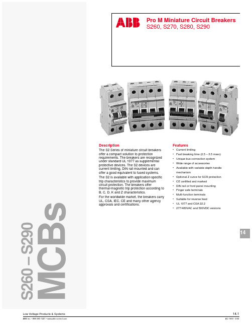
12351020307multiple of rated current123510203018multiple of rated currentKSpace foriden t i fi c a t ion markerTripping leverTrip in d i c a t orOperatorOperatingmechanismElectro-magnetic pro t ec t ionThermal protection-bimetal Upper terminalFixed contactMoving contactLower terminalDIN rail holderArc chamberUL 1077CSA C22.2 No. 235VDE 0641IEC-898Cable protectionBDelivery ClassA - Standard item, stock to 2 weeks lead timeB - Stock to 4 weeks lead timeC - 6 to 8 week lead timeD - 10 to 12 week lead timeE - Call for deliveryCUL 1077 CSA C22.2 - NO. 235VDE 0641 IEC-898Cable & equipment protectionS261-C1NA, 1P+NDelivery ClassA - Standard item, stock to 2 weeks lead timeB - Stock to 4 weeks lead timeC - 6 to 8 week lead timeD - 10 to 12 week lead timeE - Call for deliveryDUL 1077 CSA C22.2VDE 0641 IEC-898Cable & equipment protectionS263-D63, 3 poleDelivery ClassA - Standard item, stock to 2 weeks lead timeB - Stock to 4 weeks lead timeC - 6 to 8 week lead timeD - 10 to 12 week lead timeE - Call for deliveryK UL 1077CSA C22.2 - NO. 235VDE 0641IEC-898Cable & equipment protectionDelivery ClassA - Standard item, stock to 2 weeks lead timeB - Stock to 4 weeks lead timeC - 6 to 8 week lead timeD - 10 to 12 week lead timeE - Call for delivery1 KS is for standard U.S. size.UL 1077 CSA C22.2 - NO. 235VDE 0660Cable & equipment protectionDelivery ClassA - Standard item, stock to 2 weeks lead timeB - Stock to 4 weeks lead timeC - 6 to 8 week lead timeD - 10 to 12 week lead timeE - Call for deliveryUL 1077 CSA C22.2 - NO. 235VDE 0660Cable & equipment protection➀ For use with ring tongue or cable terminals only. Cannot be used with busbar system.2 No charge when ordered with the S280(W).Delivery ClassA - Standard item, stock to 2 weeks lead timeB - Stock to 4 weeks lead timeC - 6 to 8 week lead timeD - 10 to 12 week lead timeE - Call for deliveryUL 1077 VDE 0660CSA 22.2 No. 235Cable and Equip m ent Protection Direct current applicationsThe S280UC differs from standard miniature circuit breakers in that the UC versions include a permanent magnet which aids in the extinguishing of the arc during medium and high level faults. It is necessary toobserve the correct polarity and current direction when connecting the UC breakers. Two examples of correct connection are shown below.Termination points are marked on all UC type MCBs, points one (1) and four (4) are negative and points two(2) and three (3) are positive. Four pole breakers are also available for voltage reversal applications.Delivery ClassA - Standard item, stock to 2 weeks lead timeB - Stock to 4 weeks lead timeC - 6 to 8 week lead timeD - 10 to 12 week lead timeE - Call for deliveryLow Voltage Products & Systems14.13 Z UL 1077VDE 0660CSA 22.2No. 235Fast trip characteristicS281-Z16, 1 poleS282-Z32, 2 poleS283-Z32, 3 poleDiscount schedule CB7multiple of rated current multiple of rated current14.14 Low Voltage Products & SystemsVDE 0660Cable and equipment protectionDiscount schedule CB9480 VACDelivery ClassA - Standard item, stock to 2 weeks lead timeB - Stock to 4 weeks lead timeC - 6 to 8 week lead timeD - 10 to 12 week lead timeE - Call for deliveryLow Voltage Products & Systems 14.151PhaseDiscount schedule CB8For use on load side (bottom) of S260, S270, S280 and line side (top) of S280 MCBs.Insulated busbar assembly contains 2 separate circuits for use with 1, 1+N or 2 pole MCBs.For use on load side (bottom) of S260, S270, S280 and line side (top) of S280 MCBs.Insulated busbar assembly contains 3 separate circuits for use with 1 or 3 pole MCBs.For use on load side (bottom) of S260, S270, S280 and line side (top) of S280 MCBs.Delivery ClassA - Standard item, stock to 2 weeks lead timeB - Stock to 4 weeks lead timeC - 6 to 8 week lead timeD - 10 to 12 week lead timeE - Call for deliveryInsulated busbar assembly contains 4 separate circuits for use with 3+N1 or 4 pole MCBs.For use on load side (bottom) of S260, S270, S280 and line side (top) of S280 MCBs.14.16 Low Voltage Products & SystemsPhase with 1auxiliaryDiscount schedule CB8MCBs.(bottom) of S260, S270, S280 and line side (top) of S280 MCBs.Insulated busbar assembly contains 3 separate circuits for use with 1 or 3 pole MCBs. For use on load side (bottom) of S260, S270, S280 and line side (top) of S280 MCBs.(bottom) of S260, S270, S280 and line side (top) of S280 MCBs.Delivery ClassA - Standard item, stock to 2 weeks lead timeB - Stock to 4 weeks lead timeC - 6 to 8 week lead timeD - 10 to 12 week lead timeE - Call for deliveryLow Voltage Products & Systems 14.17PhaseMCB Busbar accessoriesDiscount schedule CB8For use on line side (top) of S260 and S270 MCBs.Insulated busbar assembly contains 4 separate circuits for use with 1+N or 2 pole MCBs.For use on load side (bottom) of S260, S270, S280 and line side (top) of S280 MCBs.Delivery ClassA - Standard item, stock to 2 weeks lead timeB - Stock to 4 weeks lead timeC - 6 to 8 week lead timeD - 10 to 12 week lead timeE - Call for deliveryInsulated busbar assembly contains 1 circuit for use with 1 pole MCBs.For use on line side (top) of S260 and S270 MCBs.NOTEALL BUSBARS MAY BE CENTER FED IN OR-DER TO DOUBLE THE AMPACITY RATING14.18 Low Voltage Products & SystemsFactory mountingAll accessories can be easily mounted in the fi eld. For factory mounting of any accessory devices, add $30 list to total price per breaker. To create complete catalog number, take suf fi x of accessory device following “S2-” and add suf fi x to end of breaker part number. Multiple suf fi xes must be added in alphabetical order.Example: S272-K20A1 $ 264 (2 pole, 20A breaker with type A1 shunt trip) S272-K20 @ $96 + A1@ $138 + factory mounting @ $30 = $264 S272-K20A2H11 $ 300 (2 pole, 20A breaker with type A2 shunt trip and H11 aux. contacts) S272-K20 @ $96 + A2 @ $138 + H11 @ $36 + factory mounting @ $30 = $300Auxiliary contacts and shunt trips may be mounted in combination.Discount schedule CB8NOTE: Above accesssories are for use with types S260, S270 and S280 breakers only.Delivery ClassA - Standard item, stock to 2 weeks lead timeB - Stock to 4 weeks lead timeC - 6 to 8 week lead timeD - 10 to 12 week lead timeE - Call for deliveryLow Voltage Products & Systems 14.19SA1SA2MB-3PDMB-CLS500-ME2Discount schedule CB8Delivery ClassA - Standard item, stock to 2 weeks lead timeB - Stock to 4 weeks lead timeC - 6 to 8 week lead timeD - 10 to 12 week lead timeE - Call for delivery14.20 Low Voltage Products & SystemsDiscount schedule CB8Low Voltage Products & Systems 14.21MountingUniversal mounting position using snap-on mounting to standard 35x7.5mm DIN rail.Miniature circuit breakers (MCBs) can also be mount e d to front of door using a panel cut-out with breaker handle pro t rud i ng through panel opening for external operation. Special front mount i ng kit type ME is avail a ble (see page 2.12).ConnectionTerminals are suitable for solid or fl exible conductors from 18 to 4 AWG (0.75 to 25mm 2) with no busbar connected. When max i m um busbar size of 36 mm 2 is used, maximum cable is 6 AWG (16 mm 2).Maximum tightening torque of 17.5 in-lb (2 Nm) for line/load terminals and 4.5 in-lb (0.5Nm) for ac c es s o r y device terminals.OperationMCBs are switched on by moving the handle to the upper po s i t ion. Stamped onto the handle switch, a “I” is visible con fi rming that the breaker is closed.The MCBs are “trip-free,” if the handle is being forced to the “ON” position, the breaker will still trip under fault conditions.The “O” marking indicates that the breaker is in the “OFF” position. The MCB is now open and the load is disconnected from line power.When a breaker has tripped, the MCB handle should fi rst be set to the full “OFF” position to make certain the trip mechanism has been reset. Once the fault has been determined and cleared the MCB can again be switched “ON”.MaintenanceABB miniature circuit breakers require no specialmaintenance; only normal electrical system maintenance pro c e d ures are required.Possible mounting arrangements of MCB accessoriesAuxiliary switch/bell alarmneutral disconnect Shunt trip and/or undervoltage releaseShunt trip or undervoltage release mounted with auxiliary switch14.22 Low Voltage Products & SystemsLower terminals can be bussed together with single phase or multi-phase busbars as shown. Upper ter m i n als can also be busbar con n ect e d.Dual function terminals provided in open position for connection to busbars. Pressing on screw head opens box terminal for cable insertion. Only the lower terminal is dual func t ion.Terminals allow for con n ec t ion of cable 18-4AWG. Conductors of different sizes may also be used in same terminal.Up to fi ve conductors, 16 AWG each, can be safely connected per terminal.Lower terminal can also be bussed with solidround con d uc t or.Cables can be connected to box terminals inaddition to busbar con n ec t ions on lower, dual function terminals.Thermal tripping is independent of frequency.1 Available for purchase. See page 14.19.Infl uence of frequency on electro-magnetic tripsMagnetic trip values shown on trip curves are valid for 50/60Hz ap p li c a t ions. For frequencies other than 50/60Hz, the mag n et i c (in s tan t a n eous) trip values are increased by the factor given below:16 2/3 - 60Hz100Hz 200Hz 400Hz DC Approx. factor 1 1.1 1.2 1.5 1.5Thermal tripping is independent of frequency.S260-BS280-KS270-KLet-through values I 2tFor other curves, please contact ABB Control.Version I 2t I PeakS260B TD9980 — S260C TD9981 — S260D TD9982 —S270K TD9972 TD9950 S280K TD9978 — S280Z TD9979 — S290C TD9985 —Version Amps Time-current tripS260B 6- 63 TD9725 S270K 0.5- 8 TD9705 10- 40 TD9706 50- 63 TD9707 S280K 0.2- 8 TD9708 10- 40 TD9709 50- 63 TD9710 S280Z 0.5- 63 TD9711DescriptionAll ABB miniature circuit breakers substantially reduce the maximum let-through current from the peak avail a ble short circuit current.I K - RMS current of fault I D - Max let-through of MCB V n - System voltage V B - Arc voltage of MCB t k - Breaking time of MCBType B, C, D Type K, ZCurrent carrying capacity of type “B”, “C”, “D”, “K” and “Z” thermal trip characteristics as a function of ambient tem p er a t ure.Terminal markingsInput optional from top or bottom.Miniature circuit breaker resistance valuesAmpacities for AWG wire are based on copper cable rated 75° C, except for 16AWG which is based on 60° C wire. Taken from UL508 Table 52.2.Consult applicable standards for futher detail and information. Comparison of IEC and AWG wire sizesS280S260 & S270 S290MB-CLFront mounting clipMB-3PDRHS2-MHandle mechanismAccessories12644126461265012652Many older styles of ABB miniature circuit breakers have been replaced by new and improved versions. Many of these newer styles can be directly interchanged, both electrically and physically, with the older version. There are also many international styles of ABB circuit breakers which are not normal stock items and may be inter-changed with stocked ABB versions.Note: MCB types S260/270 and S280 can be raised to the same height as older style S210 series MCBs through the use of a height adjuster (SZ-ES68/83; $ 30 list per 20). The height adjustor snaps onto the DIN rail and raises the height of com p o n ents 68mm to match that of the S210 series (83mm).S281U-K1S281UX-K1 S282UX-K10S283UX-K2014S281UX-K25LISTED10,00010001001010.10.01Current in multiples of breaker ampere rating1.02345681014.520301.0 1.35T i m e i n s e c o n d sTime –Current trip curveThermal release threshold:1.0-1.35X Magnetic release threshold:8-14.5X Ambient calibration temperature:25°CApproval UL489 UL File No. E212323 CE Marked Voltage240 VAC 1, 2, and 3 poleCurrent ratings (A) 0.2, 0.3, 0.5, 0.75, 1, 1.6, 2, 3, 4, 5, 6, 8,10, 13, 15, 16, 20, 25, 30, 32, 40, 50, 60, 63Interrupting capacity (A) 0.2 - 25A: 14kA @ 240VAC, 1, 2, and 3 pole 30 - 63A: 10kA @ 240VAC, 1, 2, and 3 pole Frequency 50/60 HzTerminals Dual function, up to (2) stripped wires plus fork style crimp terminals.Ring tongue terminal compatible Terminal range (1) 18 - 4 AWG or (2) 18 - 8 AWG (copper wire only) or (1) 18 - 4 AWG + (1) 18 - 14 AWGSolid or stranded wire, or mixedTerminal torque 18 lb.in., combination fl at blade /No. 2 posi-drive screw Service life 20,000 operations at rated loadHACR rating Heating, Air-Conditioning, and Refrigerationrating (marked on front of breaker)Ambient temperature 25° CThermal release (A) 1.0 - 1.35 x MCB amperage rating Magnetic release8 - 14.5 x MCB amperage ratingOperational temperature -25° to +55° C rangeScale 1:1141.0526.72.1053.43.1580.12.5464.51.77451.9950.5DINRAIL3.00763.54900.6917.5S281U-K_S281UX-K_S282UX-K_S283UX-K_UL 1077 CSA C22.2VDE 0641 IEC 947-2UL 1077 CSA C22.2VDE 0641 IEC 947-2Delivery ClassA - Standard item, stock to 2 weeks lead timeB - Stock to 4 weeks lead timeC - 6 to 8 week lead timeD - 10 to 12 week lead timeE - Call for deliveryUL 1077 CSA C22.2VDE 0641 IEC 947-1S502-D13Delivery ClassA - Standard item, stock to 2 weeks lead timeB - Stock to 4 weeks lead timeC - 6 to 8 week lead timeD - 10 to 12 week lead timeE - Call for deliveryUL 1077 CSA C22.2VDE 0641 IEC-898UL 1077 CSA C22.2VDE 0660Delivery ClassA - Standard item, stock to 2 weeks lead timeB - Stock to 4 weeks lead timeC - 6 to 8 week lead timeD - 10 to 12 week lead timeE - Call for deliveryS502UC-K0.15UL 1077 CSA C22.2VDE 0660Factory mount only Delivery ClassA - Standard item, stock to 2 weeks lead timeB - Stock to 4 weeks lead timeC - 6 to 8 week lead timeD - 10 to 12 week lead timeE - Call for deliveryBusbarsS500-RD3 Handle mechanism S5001 For use on 3p/3w systems, add jumper between 4 and 8N for operation of test button.Delivery ClassA - Standard item, stock to 2 weeks lead timeB - Stock to 4 weeks lead timeC - 6 to 8 week lead timeD - 10 to 12 week lead timeE - Call for deliveryApproximate dimensionsWiring diagram。
TMC低压电缆样本
Doc.No TMCSS-05025Issued Date Dec. 22, 2005Page. No 1 of 38SPECIFICATIONDocument Title :0.6/1kV HALOGEN FREE POWER & CONTROL CABLES(FLAME RETARDANT / FIRE RESISTANCE)Type designation :0.6/1kV TI, 0.6/1kV TFOI0.6/1kV BI, 0.6/1kV BFOI1 2005. 12. 22 Revised & updated by DNV comments0 2005. 8. 22 First issueREV. DATE DESCRIPTION Prepared by Checked by Approved bySpecialized Company for Offshore&Marine CablesPage 2 of 38 1. SCOPEThis specification covers 0.6/1kV (U0/U) flame retardant or fire resistance, low smoke and halogen free power, lighting and control cables which shall be in accordance with IEC 60092-350 and IEC 60092-353.2. REFERENCE STANDARDIEC Pub. 60228 Conductors of insulated cablesIEC Pub. 60092-350 Low voltage shipboard power cablesGeneral construction and test requirementsIEC Pub. 60092-353 Single and multicore non-radial field power cables with extruded solidinsulation for rated voltage 1kV and 3kVIEC Pub. 60092-351 Insulating materials for shipboard power cables.IEC Pub. 60092-359 Sheathing materials for shipboard power and telecommunication cablesIEC Pub. 60332-1 Tests on electric cables under fire conditionsPart 1 : Test on a single vertical insulated wire or cableIEC Pub. 60332-3-22 Tests on electric cables under fire conditionsPart 3-22 : Test for vertical flame spread of vertically-mounted bunchedwires or cables - Category AIEC Pub. 60331-21 Tests for electric cables under fire conditionsPart 21 : Procedures and requirements - Cables of rated voltage up toand including 0.6/1.0kVIEC Pub. 60754-1,2 Test on gases evolved during combustion of materials from cables.Part 1 : Determination of the amount of halogen acid gas.Part 2 : Determination of degree of acidity of gases evolved duringthe combustion of materials taken from electric cables by measuringpH and conductivity.IEC 61034-1,2 Measurement of smoke density of electric cables burning under defined conditions Part 1 : Test apparatus.Part 2 : Test procedures and requirements.Page 3 of 38 3. CABLE TYPE AND DESIGNATIONThe type and symbols of cables are as given in following tables.Table 1. Type and DesignationsCable type Designation Attached table No.0.6/1kV Single ~ Multi core, XLPE insulated, SHF1 sheathed Flameretardant power & control cable0.6/1kV TI 1-1 ~ 1-7 0.6/1kV Single ~ Multi core, XLPE insulated, Lapped inner covering,Plain annealed copper wire braid armoured, SHF1 sheathed Flameretardant power & control cable0.6/1kV TFOI 2-1 ~ 2-70.6/1kV Single ~ Multi core, Mica/glass taped, XLPE insulated, SHF1sheathed Flame retardant & Fire resistance power & control cable0.6/1kV BI 3-1 ~ 3-7 0.6/1kV Single ~ Multi core, Mica/glass taped, XLPE insulated, Lappedinner covering, Plain annealed copper wire braid armoured, SHF1sheathed Flame retardant & Fire resistance power & control cable0.6/1kV BFOI 4-1 ~ 4-7Table 2. Symbols of materialsInsulation InnerCovering Armour Sheath T XLPEB Mica + XLPE FNon-hygroscopicmaterialOCopper wirebraidIHalogen free thermoplasticcompound (SHF1)4. CONSTRUCTION AND MATERIALThe construction and material of cable shall be as follows;4.1. ConductorThe conductor shall be stranded circular conductor composed of plain annealed copper wire in accordance with IEC Pub. 60228, Class2.4.2. Fire-resisting layer (Fire resistance cable only)The fire-resisting layer shall be mica/glass tape applied by lapping helically on the conductor.Page 4 of 384.3. InsulationThe insulation shall consist of an extruded layer of cross-linked polyethylene (XLPE) and shall comply with the requirement of IEC 60092-351.The average thickness of insulation shall be not less than the specified value given in the table. The thickness at any place may be less than the specified value provided the difference does not exceed0.1㎜ + 10%of the specified value.4.4. CablingThe required number of cores shall be cabled together with suitable lay length.Non-hygroscopic material may be applied to the center and the interstice between cores to form a compact circular shape. Suitable binder tape may be applied over the cabled cores.4.5. Inner covering ( TFOI & BFOI Type only )The inner covering shall be non-hygroscopic suitable tapes.The approximate thickness of the inner covering shall be 0.4mm for fictitious diameter over laid-up cores up to and including 40mm and 0.6mm for lager diameter.4.6. Armour ( TFOI & BFOI Type only )The armour shall be braided plain annealed copper wires.The diameter of wire shall comply with the value given in the table and all individual measured values shall be not smaller than 90% of the nominal value minus 0.03 mm, and not greater than 110%of the average value plus 0.03 mm.The coverage density of braid shall be not less than 90% when tested by clause 11.6 (b) ofIEC 60092-350. Suitable tape(s) may be applied over the armour at manufacturer's option.4.7. SheathThe sheath shall be an extruded layer of halogen free thermoplastic compound and shall comply with requirements of designation SHF1 in IEC 60092-359.The average thickness of the sheath shall be not less than the specified nominal value given in the table and the minimum thickness at any point shall not fall below 85%of the nominal value by more than 0.1mm.As a rule, the color of sheath shall be "Black".The other color of sheath may be applicable when purchaser required.5. IDENTIFICATIONPage 5 of 38No. of cores Method 1 (without ground core) Method 2 (with ground core) 1C Black - 2C Red , Black -3C / 3G Red , Yellow, Blue Red , Yellow, Yellow/Green4C / 4G Red , Yellow, Blue, Black Red , Yellow, Blue, Yellow/Green5 and over (5G and over) Black number on White insulationBlack number on White insulation PlusYellow/GreenNote) 1. The letter "-G" means that the cable has the earth core.2. Yellow/Green means green base colored insulation with yellow stripe.3. Any other color scheme may be applicable when purchaser required.6. TESTThe following test shall be carried out in accordance with IEC 60092-350, IEC 60092-353 and this specification.6.1.Routine testRoutine tests shall be carried out all cables manufactured, and shall be in accordance with specified standards.6.1.1.Conductor resistance test per clause 10.2 of IEC 60092-350.6.1.2. High voltage test per clause 10.3 of IEC 60092-350.6.1.3.Insulation resistance test per clause 10.4 of IEC 60092-350.6.2. Special testThe following special test shall be carried out in accordance with specified standards.6.2.1. Conductor examination test per clause 11.3 of IEC 60092-350.6.2.2. Check of dimension test per clause 11.4 to 11.7 of IEC 60092-350.6.2.3. Hot set test per clause 11.8 of IEC 60092-350.6.2.4. Low temperature test per clause 11.9 of IEC 60092-350.Page 6 of 38 6.3. Type test, electricalThe following electrical type test shall be carried out in accordance with specified standards.6.3.1. Insulation resistance test per clause 12.2 of IEC 60092-350.6.3.2. High voltage test for 4h per clause 12.4 of IEC 60092-350.6.4. Type test, non-electricalThe following non-electrical type test shall be carried out in accordance with specified standards.6.4.1. Measurement of thickness of insulation test per clause 13.1 of IEC 60092-350.6.4.2. Measurement of thickness of sheath test per clause 13.2 of IEC 60092-350.6.4.3. Non-electrical characteristics of insulation test per clause 13.3 and 13.11 ofIEC 60092-350.6.4.4. Non-electrical characteristics of sheath test per clause 13.4, 13.7, 13.8, 13.9 and 13.18 of IEC60092-350.6.4.5. Additional ageing test on pieces of completed cable per clause 13.5 of IEC 60092-350.6.4.6. Flame retardant test per IEC 60332-1.6.4.7. Flame retardant test for IEC 60332-3-22 Category A'6.4.8. Fire resisting test per IEC 60331-21. (Applied to Fire resistance cables only)6.4.9. Smoke emission test per IEC 61034-2.The minimum value shall be 60%.6.4.10. Oil Resistant(Immersion) test per clause 13.12 of IEC 60092-350. (at purchaser’s request)The test condition shall be 70±2℃, 4hour6.4.11. Cold Bending test (at -40℃) and cold impact (at -35℃) test shall be carried out inaccordance with CSA C22.2 No.38, No.0.3 (at purchaser’s request)Page 7 of 38 7. MARKING ON CABLEThe cable shall be marked with the following informations through the length of cable.The marking shall be repeated at least every 1 meter.The other information can be added in marking when purchaser required.7.1. Rated voltage7.2. Cable type7.3. Cable size7.4. Application standard (if necessary)7.5. Manufacturer's name7.6. Year of manufacture7.7. Length of cable in meterex) 0.6/1kV TFOI 95SQMM x 3C TMC 2005 0001M8. MARKING ON DRUMOn a flange of the drum, necessary information such as manufacturer's name, cable type, size, rated voltage, length of cable, drum no., gross weight, net weight, etc. shall be printed. An arrow shall be printed on the drum with suitable instructions to show the direction of rotation of the drum.9. PACKINGThe completed cable shall be placed on the wooden drum in such a manner that it will be protected from damages during transportation. The both ends of the complected cable be sealed by cap.Page 8 of 38APPENDIX ACHARACTERISTICS OF INSULATION (Comply with IEC 60092-351)Materials XLPE Maximum rated conductor temperature(℃)90Electrical characteristicsInsulation resistance constant K i(㏁·㎞)a) at 20 ℃Minimumb) at maximum operating temperature Minimum 3670 3.67Mechanical characteristics Without ageingTensile strength Minimum N/㎟ Elongation at break Minimum % 12.5 200After ageing in air ovenTemperature ℃Duration hours Tensile strengtha) Minimum value N/㎟b) Variation Maximum % Elongation at breaka) Minimum value %b) Variation Maximum % 135±2 168-±25-±25Particular characteristics Hot set testTemperature ℃Time under load Minute Mechanical stress N/㎠Elongation under load Maximum %Permanent elongation Maximum % 200±3 15 20 175 15Page 9 of 38APPENDIX BCHARACTERISTICS OF SHEATH (Comply with IEC 60092-359)Materials SHF1 Maximum rated conductor temperature(℃)85 Mechanical characteristicsWithout agingTensile strength Minimum N/㎟ Elongation at break Minimum % 9.0 120After aging in air ovenTemperature ℃Duration hours Tensile strengtha) Minimum value N/㎟b) Variation Maximum %c) Percentage of value found on the unaged specimenMinimum %Elongation at breaka) Minimum value %b) Variation Maximum %c) Percentage of value found on the unaged specimenMinimum % 100±2 1687.0 ±30-110 ±30-Particular characteristicsPressure test at high temperatureTemperature ℃ Duration under load - for cable having an outer diameter 〈 12.5mm hours - for cable having an outer diameter 〉12.5mm hours Maximum permissible deformation % 80±24 6 50Heat shock testTemperature ℃ Duration hours Result of heat shock test150±31No crackPage 10 of 38APPENDIX BCHARACTERISTICS OF SHEATH (cont)Materials SHF1Maximum rated conductor temperature(℃)85Behaviour at low temperaturesBending test(for cables with outer diameter upto and including 12.5mm)Temperature ℃ Duration hours Result of bending test-15±216 No crackElongation test (for cables not subjected to the bending test)Temperature ℃Duration hours Elongation at rupture Minimum % -15±24 20Cold impactTemperature ℃Duration hours Result of cold impact test-15±216 No crackMechanical characteristics A)After immersion in hot oil (IEC 60811-2-1. clause 10)Temperature ℃Duration hours Minimum variationa) Tensile strength %b) Elongation % 70±2 4±40 ±40Amount of halogen acid gas Maximum mg/g (%) 5 (0.5)Smoke light transmittance Minimum % 60Cold resistant (CSA C22.2 No.38, No.0.3) B)Bending testTemperature ℃ Duration hours Result of bending testCold impactTemperature ℃Duration hours Result of bending test-40±14No crack-35±14No crackDoc. No. TMCSS-05025Page 11 of 38 T a b l e1-1* CONSTRUCTION1. Conductor : Plain annealed copper wires2. Insulation : XLPE3. Sheath : SHF1* NOTE1. A suitable tape may be applied on the conductor.* REFERENCE1. Rated voltageU0/U(U m) = 0.6/1(1.2) kV2. Max. rated conductor temperature : 90℃3. Color of sheath : BlackDoc. No. TMCSS-05025Page 12 of 38 T a b l e1-21. Conductor : Plain annealed copper wires2. Insulation : XLPE5. Sheath : SHF13. Cabling (with filler)4. Binder tape* CONSTRUCTION* NOTE1. A suitable tape may be applied on the conductor.* REFERENCE1. Rated voltageU0/U(U m) = 0.6/1(1.2) kV2. Max. rated conductor temperature : 90℃3. Color of sheath : BlackDoc. No.TMCSS-05025 Page13 of 38T a b le 1-3* CONSTRUCTION 1. Conductor : Plain annealed copper wires 2. Insulation : XLPE 5. Sheath : SHF13. Cabling (with filler)4. Binder tape* NOTE1. A suitable tape may be applied on the conductor.* REFERENCE1. Rated voltageU 0/U(U m ) = 0.6/1(1.2) kV2. Max. rated conductor temperature : 90℃3. Color of sheath : BlackDoc. No. TMCSS-05025Page 14 of 38 T a b l e1-41. Conductor : Plain annealed copper wires2. Insulation : XLPE5. Sheath : SHF13. Cabling (with filler)4. Binder tape* CONSTRUCTION* NOTE1. A suitable tape may be applied on the conductor.* REFERENCE1. Rated voltageU0/U(U m) = 0.6/1(1.2) kV2. Max. rated conductor temperature : 90℃3. Color of sheath : BlackDoc. No. TMCSS-05025Page 15 of 38 T a b l e1-51. Conductor : Plain annealed copper wires2. Insulation : XLPE5. Sheath : SHF13. Cabling (with filler)4. Binder tape* CONSTRUCTION* NOTE1. A suitable tape may be applied on the conductor.* REFERENCE1. Rated voltageU0/U(U m) = 0.6/1(1.2) kV2. Max. rated conductor temperature : 90℃3. Color of sheath : BlackDoc. No. TMCSS-05025Page 16 of 38 T a b l e1-6* Cable construction is the same Attached Table 1-5Doc. No. TMCSS-05025Page 17 of 38 T a b l e1-7* Cable construction is the same Attached Table 1-5Doc. No. TMCSS-05025Page 18 of 38 T a b le2-11. Conductor : Plain annealed copper wires2. Insulation : XLPE5. Sheath : SHF13. Inner covering (lapped)4. Armour : Braid of copper wires* CONSTRUCTION* NOTE1. A suitable tape may be applied on the conductor.2. A suitable tape may be applied on the armour.3. The material of armour can be copper alloy wire forcopper wire. When purchaser required.* REFERENCE1. Rated voltageU0/U(U m) = 0.6/1(1.2) kV2. Max. rated conductor temperature : 90℃3. Color of sheath : BlackDoc. No. TMCSS-05025Page 19 of 38 Table 2-21. Conductor : Plain annealed copper wires2. Insulation : XLPE5. Armour : Braid of copper wires3. Cabling (with filler)4. Inner covering (lapped)6. Sheath : SHF1* CONSTRUCTION* NOTE1. A suitable tape may be applied on the conductor.2. A suitable tape may be applied on the armour.3. The material of armour can be copper alloy wire forcopper wire. When purchaser required.* REFERENCE1. Rated voltageU0/U(U m) = 0.6/1(1.2) kV2. Max. rated conductor temperature : 90℃3. Color of sheath : BlackDoc. No. TMCSS-05025Page 20 of 38 T a b le2-31. Conductor : Plain annealed copper wires2. Insulation : XLPE5. Armour : Braid of copper wires3. Cabling (with filler)4. Inner covering (lapped)6. Sheath : SHF1* CONSTRUCTION* NOTE1. A suitable tape may be applied on the conductor.2. A suitable tape may be applied on the armour.3. The material of armour can be copper alloy wire forcopper wire. When purchaser required.* REFERENCE1. Rated voltageU0/U(U m) = 0.6/1(1.2) kV2. Max. rated conductor temperature : 90℃3. Color of sheath : BlackDoc. No. TMCSS-05025Page 21 of 38 T a b le2-41. Conductor : Plain annealed copper wires2. Insulation : XLPE5. Armour : Braid of copper wires3. Cabling (with filler)4. Inner covering (lapped)6. Sheath : SHF1* CONSTRUCTION* NOTE1. A suitable tape may be applied on the conductor.2. A suitable tape may be applied on the armour.3. The material of armour can be copper alloy wire forcopper wire. When purchaser required.* REFERENCE1. Rated voltageU0/U(U m) = 0.6/1(1.2) kV2. Max. rated conductor temperature : 90℃3. Color of sheath : BlackDoc. No. TMCSS-05025Page 22 of 38 T a b le2-51. Conductor : Plain annealed copper wires2. Insulation : XLPE5. Armour : Braid of copper wires3. Cabling (with filler)4. Inner covering (lapped)6. Sheath : SHF1* CONSTRUCTION* NOTE1. A suitable tape may be applied on the conductor.2. A suitable tape may be applied on the armour.3. The material of armour can be copper alloy wire forcopper wire. When purchaser required.* REFERENCE1. Rated voltageU0/U(U m) = 0.6/1(1.2) kV2. Max. rated conductor temperature : 90℃3. Color of sheath : BlackDoc. No. TMCSS-05025Page 23 of 38 T a b le2-6* Cable construction is the same Attached Table 2-5Doc. No. TMCSS-05025Page 24 of 38 T a b le2-7* Cable construction is the same Attached Table 2-5Doc. No. TMCSS-05025Page 25 of 38 T a b l e3-11. Conductor : Plain annealed copper wires2. Fire resisting tape4. Sheath : SHF13. Insulation : XLPE* CONSTRUCTION* NOTE1. A suitable tape may be applied on the fire-resisting tape.* REFERENCE1. Rated voltageU0/U(U m) = 0.6/1(1.2) kV2. Max. rated conductor temperature : 90℃3. Color of sheath : BlackDoc. No. TMCSS-05025Page 26 of 38 T a b l e3-21. Conductor : Plain annealed copper wires2. Fire resisting tape5. Binder tape3. Insulation : XLPE4. Cabling (with filler)6. Sheath : SHF1* CONSTRUCTION* NOTE1. A suitable tape may be applied on the fire-resisting tape.* REFERENCE1. Rated voltageU0/U(U m) = 0.6/1(1.2) kV2. Max. rated conductor temperature : 90℃3. Color of sheath : BlackDoc. No. TMCSS-05025Page 27 of 38 T a b le3-31. Conductor : Plain annealed copper wires2. Fire resisting tape5. Binder tape3. Insulation : XLPE4. Cabling (with filler)6. Sheath : SHF1* CONSTRUCTION* NOTE1. A suitable tape may be applied on the fire-resisting tape.* REFERENCE1. Rated voltageU0/U(U m) = 0.6/1(1.2) kV2. Max. rated conductor temperature : 90℃3. Color of sheath : BlackDoc. No. TMCSS-05025Page 28 of 38 T a b l e3-41. Conductor : Plain annealed copper wires2. Fire resisting tape5. Binder tape3. Insulation : XLPE4. Cabling (with filler)6. Sheath : SHF1* CONSTRUCTION* NOTE1. A suitable tape may be applied on the fire-resisting tape.* REFERENCE1. Rated voltageU0/U(U m) = 0.6/1(1.2) kV2. Max. rated conductor temperature : 90℃3. Color of sheath : BlackDoc. No. TMCSS-05025Page 29 of 38 T a b l e3-51. Conductor : Plain annealed copper wires2. Fire resisting tape5. Binder tape3. Insulation : XLPE4. Cabling (with filler)6. Sheath : SHF1* CONSTRUCTION* NOTE1. A suitable tape may be applied on the fire-resisting tape.* REFERENCE1. Rated voltageU0/U(U m) = 0.6/1(1.2) kV2. Max. rated conductor temperature : 90℃3. Color of sheath : BlackDoc. No. TMCSS-05025Page 30 of 38 T a b l e3-6* Cable construction is the same Attached Table 3-5Doc. No. TMCSS-05025Page 31 of 38 T a b l e3-7* Cable construction is the same Attached Table 3-5Doc. No. TMCSS-05025Page 32 of 38 T a b le4-11. Conductor : Plain annealed copper wires2. Fire resisting tape5. Armour : Braid of copper wires3. Insulation : XLPE4. Inner covering (lapped)6. Sheath : SHF1* CONSTRUCTION* NOTE1. A suitable tape may be applied on the fire-resisting tape.2. A suitable tape may be applied on the armour.3. The material of armour can be copper alloy wire forcopper wire. When purchaser required.* REFERENCE1. Rated voltageU0/U(U m) = 0.6/1(1.2) kV2. Max. rated conductor temperature : 90℃3. Color of sheath : BlackDoc. No. TMCSS-05025Page 33 of 38 T a b le4-21. Conductor : Plain annealed copper wires2. Fire resisting tape6. Armour : Braid of copper wires3. Insulation : XLPE4. Cabling (with filler)7. Sheath : SHF15. Inner covering (lapped)* CONSTRUCTION* NOTE1. A suitable tape may be applied on the fire-resisting tape.2. A suitable tape may be applied on the armour.3. The material of armour can be copper alloy wire forcopper wire. When purchaser required.* REFERENCE1. Rated voltageU0/U(U m) = 0.6/1(1.2) kV2. Max. rated conductor temperature : 90℃3. Color of sheath : BlackDoc. No. TMCSS-05025Page 34 of 38 T a b le4-31. Conductor : Plain annealed copper wires2. Fire resisting tape6. Armour : Braid of copper wires3. Insulation : XLPE4. Cabling (with filler)7. Sheath : SHF15. Inner covering (lapped)* CONSTRUCTION* NOTE1. A suitable tape may be applied on the fire-resisting tape.2. A suitable tape may be applied on the armour.3. The material of armour can be copper alloy wire forcopper wire. When purchaser required.* REFERENCE1. Rated voltageU0/U(U m) = 0.6/1(1.2) kV2. Max. rated conductor temperature : 90℃3. Color of sheath : BlackDoc. No. TMCSS-05025Page 35 of 38 T a b le4-41. Conductor : Plain annealed copper wires2. Fire resisting tape6. Armour : Braid of copper wires3. Insulation : XLPE4. Cabling (with filler)7. Sheath : SHF15. Inner covering (lapped)* CONSTRUCTION* NOTE1. A suitable tape may be applied on the fire-resisting tape.2. A suitable tape may be applied on the armour.3. The material of armour can be copper alloy wire forcopper wire. When purchaser required.* REFERENCE1. Rated voltageU0/U(U m) = 0.6/1(1.2) kV2. Max. rated conductor temperature : 90℃3. Color of sheath : BlackDoc. No. TMCSS-05025Page 36 of 38 T a b le4-51. Conductor : Plain annealed copper wires2. Fire resisting tape6. Armour : Braid of copper wires3. Insulation : XLPE4. Cabling (with filler)7. Sheath : SHF15. Inner covering (lapped)* CONSTRUCTION* NOTE1. A suitable tape may be applied on the fire-resisting tape.2. A suitable tape may be applied on the armour.3. The material of armour can be copper alloy wire forcopper wire. When purchaser required.* REFERENCE1. Rated voltageU0/U(U m) = 0.6/1(1.2) kV2. Max. rated conductor temperature : 90℃3. Color of sheath : BlackDoc. No. TMCSS-05025Page 37 of 38 T a b le4-6* Cable construction is the same Attached Table 4-5Doc. No. TMCSS-05025Page 38 of 38 T a b le4-7* Cable construction is the same Attached Table 4-5。
1169∕08—2007 光伏电缆标准

2 Pfg 1169/08.2007 Requirements forcables for use in photovoltaic-systemsContentsSeite Foreword (3)1Scope (3)2Normative references (3)3Terms and definitions (5)4Halogen-free PV-cable (6)4.1Code designation (6)4.2Characteristics (6)4.3Construction (6)4.4Test (8)4.5Guideline for use (informative) (8)4.6Current carrying capacity (8)Annex A (normative) Test of mutual influence (15)Annex B (normative) Test of absence of halogen (16)Annex C (normative) Determination of halogens – Elemental test (17)Annex D (normative) Test of long term resistance of insulation to D.C (19)Annex E (normative) Cold impact test (20)Annex F (normative) Dynamic penetration test (21)Annex G (normative) Notch propagation (23)Figure 1 – Arrangement of marking (8)Figure F.1 – Arrangement for penetration test (22)Table 1 – Current carrying capacity of PV-cables (9)Table 2 – Conversion factor for deviating temperatures (9)Table 3 – Tests for halogen free PV-cable (10)Table 4 – Requirements for halogen free insulation and sheath compounds (13)Table A.1 – Requirements (15)Table B.1 – Test method, measurement, requirements (16)Table B.2 – Test sequence (16)Table E.1 – Parameter for cold impact test (20)ForewordThis test specification contents the requirements listed in a manuscript of the working group AK 411.2.3 …Leitungen für PV-Systeme“ of the German committee for standardization (DKE). This manuscript is intended to be published as German pre-standard. Up to the date of publishing of the pre-standard this test-specification of TUV Rheinland will be used for test and assessment of cables for use in PV-systems (PV-cables).1 Scope2 PfG 1169/08.2007 applies to flexible single-core cables (cords) for use at the DC-side of photovoltaic-systems with a maximum permissible voltage of DC 1,8 kV (conductor/conductor, non earthed system). The cables are suitable for use in safety class II.It is permitted to connect these cables as multiple-construction.The cables are intended to operate at ambient temperature until 90°C2 Normative referencesThe following referenced documents are indispensable for the application of this document. For dated references, only the edition cited applies. For undated references, the latest edition of the referenced document (including any amendments) applies.IEC 60364-5-52, Erection of low voltage installations –Part 5: Selection and erection of electrical equipment –Chapter 52: Wiring systemsEN 50267-2-1, Common test methods for cables under fire conditions – Tests on gases evolved during combustion of materials from cables – Part 2-1: Procedures – Determination of the amount of halogen acid gas;EN 50267-2-2, Common test methods for cables under fire conditions – Tests on gases evolved during combustion of materials from cables – Part 2-2: Procedures – Determination of degree of acidity of gases for materials by measuring pH and conductivity;EN 50305, Railway applications – Railway rolling stock cables having special fire performance – Test methodsEN 50395, Electrical test methods for low voltage energy cables;EN 50396, Electrical test methods for low voltage energy cables;EN 60068-2-78, Environmental testing - Part 2-78: Tests -Test Cab: Damp heat, steady state (IEC 60068-2-78)EN 60216-1, Electrical insulating materials - Properties of thermal endurance - Part 1: Ageing procedures and evaluation of test results (IEC 60216-1);EN 60216-2, Electrical insulating materials – Thermal endurance properties – Part 2: Determination of thermal endurance properties of electrical insulating materials – Choice of test criteria (IEC 60216-2);EN 60228, Conductor of insulated cables (IEC 60228)EN 60332-1-2, Tests on electric and optical fibre cables under fire conditions – Part 1-2: Test for vertical flame propagation for a single insulated wire or cable – Procedure for 1 kW pre-mixed flame; (IEC 60332-1-2)EN 60684-2, Flexible insulating sleeving – Part 2: Methods of test (IEC 60684-2)EN 60811-1-1, Insulating and sheathing materials of electric cables – Common test methods Part 1-1: General application – Measurement of thickness and overall dimensions – Test for determining the mechanical properties (IEC 60811-1-1)EN 60811-1-2, Insulating and sheathing materials of electric and optical cables – Common test methods. Part 1-2: General application. Thermal ageing methods (IEC 60811-1-2)EN 60811-1-3, Insulating and sheathing material of electric and optical cables – Common test methods – Part 1-3: General application – Methods for determining the density – Water absorption tests – Shrinkage test (IEC 60811-1-3)EN 60811-1-4, Insulating and sheathing materials of electric and optical cables – Common test methods. Part 1-4: General application. Tests at low temperature. (IEC 60811-1-4)EN 60811-2-1, Insulating and sheathing materials of electric and optical cables – Common test methods – Part 2-1: Methods specific to elastomeric compounds – Ozone resistance, hot set and mineral oil immersion tests (IEC 60811-2-1)EN 60811-3-1, Insulating and sheathing materials of electric cables – Common test methods Part 3-1: Methods specific to PVC compounds – Pressure test at high temperature, test for resistance to cracking (IEC 60811-3-1)HD 22.13, Rubber insulated cables of rated voltages up to and including 450/750 V Part 13: Single and multicore flexible cables, insulated and sheathed with crosslinked polymer and having low emission of smoke and corrosive gases;HD 605, Power cables – Part 605: Additional test methodsHD 60364-7-712Electrical installations of buildings – Part 7-712: Requirements for special installations or locations – Solar photovoltaic (PV) power supply systems (IEC 60364-7-712, modified)3 Terms and definitionsFor the purposes of this document, following definitions apply.3.1 Terms for test procedure3.1.1Type test (symbol T)Tests required to be made before supplying a type of cable covered by this standard on a general commercial basis, in order to demonstrate satisfactory performance characteristics to meet the intended application. These tests are of such a nature that, after they have been made, they need not be repeated, unless changes are made in the cable materials or design or manufacturing process which might change the performance characteristics.3.1.2sample tests (symbol S)Tests made on samples of completed cable or components taken from a completed cable, at a specified frequency, so as to verify that the finished product meets the specified requirements.3.1.3Routine tests (symbol R)Tests made by the manufacturer on each manufactured length of cable to check that each length meets the specified requirements3.2Rated voltageThe rated voltage of the cable determines the construction and the tests of the cable with regard to the electrical properties.The rated voltage is designated by two values of frequency voltage: U0/U in VoltU0 rated power frequency voltage between conductor and earth (metallic screen of cable or ambient medium);U rated power frequency voltage between two conductors of a multipole cable or of a system of single core cables.The rated voltage of the cable for a given application shall be suitable for the operating conditions in the system in which the cable is used.This requirement is applicable for both U o and UThe rated voltage between two conductors in a DC-system shall not exceed the 1,5 time value of rated voltage U of the cable, and the rated voltage between conductor and earth shall not exceed the 1,5 time value of rated voltage U o of the cable.NOTE The operating voltage of a system may exceed is rated voltage permanent for 20%. A cable may be operated with a voltage which value is 20% higher than rated voltage under condition that the rated voltage is not less than the rated voltage of the system.3.3DC sidepart of a PV installation from a PV cell to the DC terminals of the PV inverter3.4open-circuit voltage under standard test conditions U OC STCvoltage under standard test conditions across an unloaded (open) PV module, PV string, PV array, PV generator or on the DC side of the PV inverter3.5short-circuit current under standard test conditions I SC TCshort-circuit current of a PV module, PV string, PV array or PV generator under standard test conditions4 Halogen free PV-cable4.1 Code designationPV1-F4.2 Characteristics4.2.1Rated voltageAC U 0/U 0,6/1 kVDC 1,8 kV (conductor-conductor, non earthed system, circuit not under load).If the cable is used in DC-systems the rated voltage between two conductors shall not exceed the 1,5 time value of rated voltage U of the cable. In with single-phase earthed DC-systems this value shall be multiplied with factor 0,5. 4.2.2Temperature rangeAmbient temperature:–40 °C to +90 °C Max. temperature at conductor:120 °CThe cables are intended to operate at ambient temperature until 90°C. For this a temperature index of120°C applies to the insulation and the sheath, bas ed on EN 60216-1 (20.000h, 50% residual elongation). NoteThe expected period of use is 25 years.The permitted short-circuit-temperature refer to a period of 5s is 200°C.4.3 Construction4.3.1Conductor Number of conductors: 1The conductor shall be class 5, according to EN 60228. The single wires must be tinned. Preferred diameters: 2,5, 4, 6, 10, 16 mm 24.3.2Separation layerA separation layer of a suitable halogen free material may be applied around the conductor.额定电压导体工作温度导体绝缘4.3.3 InsulationThe insulation shall be a suitable halogen free material applied around the conductor.The insulation shall be extruded and shall consist of one or several adjacent adherent layers. It shall be solid and homogeneous, it must be possible to remove it without damage to the insulation itself, to the conductor and to the tin coating.The insulation shall be smooth, consistently applied and largely circular. Compliance shall be checked by inspection and by manual test.The wall thickness of insulation is specified by the manufacturer, but it must not fall short of the minimum value of 0,5mm.4.3.4 Separation layerA separation layer of a suitable halogen free material may be applied around the insulation.4.3.5 SheathThe core must be covered by a sheath.The sheath around the core must be of a suitable halogen free material.The sheath shall be extruded and shall consist of one or several adjacent adherent layers. The sheath shall be smooth and consistently applied.The wall thickness of sheath is specified by the manufacturer, but it must not fall short of the minimum value of 0,5mm.4.3.6 Outer diameterThe average value of the outer diameter shall be within the limits specified by the manufacturer.4.3.7 Multiple constructionEach single-core cable in a multiple construction shall pass the requirements of this document. Each additional component in a multiple construction shall pass the requirements of this document.4.3.8 Marking4.3.8.1 GeneralThe cable shall be marked as follows:a) Trademark;b) Code designation;c) Rated diameter.Marking may be by printing or by reproduction in relief on or in the sheath.4.3.8.2 TrademarkCables shall be provided with an indication of the manufacturer, which consist of a consecutively marking with company name or company sign or with (if trademarked) an identification number.4.3.8.3 Code designationCables shall be provided with an code designation according to 4.1 applied consecutively on sheath.4.3.8.4 Arrangement of markingEach marking is considered as consecutive if the spacing between the end of a marking and the begin of the following identical marking does not exceed following value:– 550mm, for marking on sheath or outer jacket.Following figure shows an example of marking on sheath.Figure 1 – Arrangement of marking4.3.8.5 DurabilityPrinted markings shall be durable. Compliance with this requirement shall be checked by the test given in 5.1 of EN 50396.4.3.8.6 LegibilityEach marking shall be legible.4.4 TestCompliance with the requirements of 4.3 shall be checked by visual inspection and tests according to table3.4.5 Guideline for use (informative)Cables according to this standard are intended for use in PV-systems according to EN 60364-7-712.4.6 Current carrying capacityAmbient temperature: 60°CMax. temperature at conductor: 120 °CTable 1 – Current carrying capacity of PV-cablesKind of installationRated diameter Single cable free inair Single cable onsurfacesTo cables adjacent onsurfacesmm2 A A A1,5 30 29 242,5 41 39 334 55 52 446 70 67 5710 98 93 7916 132 125 10725 176 167 14235 218 207 176Table 2 – Conversion factor for deviating temperaturesAmbient temperature Conversion factor°CUp to 60 1,0070 0,9180 0,8290 0,71100 0,58110 0,41Reduction factor for accumulation according to IEC 60364-5-52, Table B.52-17Table 3 – Tests for halogen free PV-cableNo. Test Requirementsof test standard clause5 Resistance against acid and alkalinesolutionT EN 60811-2-1 10 5.1Chemical stressacid: N-Oxal-acidalkaline solution: N-sodium hydroxide solutiontemperature °C 23duration h 1685.2Tensile strength:variation, max. % ± 305.3Elongation at break, min. % 1006 Test of influence T Annex A7 Cold impact test at –40 °C T Annex E8 Cold bending testDiameter of cable < 12,5 mmT EN 60811-1-4 8.2 8.1 Test conditions:– temperature °C –40 ± 2– duration of conditioning h 16 EN 60811-1-4 8.2.3 8.2 Results to be obtained Absence ofcracks9 Cold elongation testDiameter of cable ≥ 12,5 mmTable 3 10 Ozone resistance at complete cable T10.1 Method B EN 50396 8.1.3– temperature °C 40 ± 2– relative humidity % 55 ± 5– duration h 72– Ozone concentration %(by volume)(200 ± 50) × 10–610.2 Results to be obtained Absence ofcracks.11 Weathering/UV-resistance T HD 605/A1 2.4.20 11.1 Conditions:– duration h 720– temperature °C(Black-Standard-temperature)63– relative humidity % 65– min. power at W/m2wavelength 300 nm to 400 nm60 ± 2– duration spraying/drying min 18/102Results to be obtained Absence ofcracks.12 Dynamic penetration test T Annex F13 Notch propagation T Annex GNo. Test Requirementsof test standard clause14 Shrinkage test at complete cable T EN 60811-1-3 11((sheath)) 14.1 Conditions:– temperature °C 120– duration h 1– Distance L of sample mm 30014.2 Results to be obtained:– Maximum shrinkage. % 215 Test under fire conditions15.1 Test for vertical flame propagation at completecableT, S EN 60332-1-215.2 Assessment of halogen T, S15.2.1 Absence of halogen Annex B 15.2.2 Determination of halogens – Annex CTable 4 – Requirements for halogen free insulation and sheath compounds1 2 3 4 5 6 7Test method described in Type of compoundRef. No. Test Unitstandard clause insulation sheath1 Mechanical characteristics1.1 Properties before ageing EN 60811-1-1 9.21.1.1 Values to be obtained for the tensile strength:– median, min. N/mm26,5 8,01.1.2 Values to be obtained for the elongation atbreak:– median, min. % 125 125 1.2 Properties after ageing in oven EN 60811-1-2 8.11.2.1 Ageing conditions:– temperature °C 150 ± 2 150 ± 2 – duration of treatment h 7 × 24 7 × 24 1.2.2 Values to be obtained for the tensile strength:c– median, min. N/mm2– – – variation, max. % –30a–30a1.2.3 Values to be obtained for the elongation atbreak:c– median, min. % – – – variation, max. % – 30a– 30a 1.3 Hot set test d EN 60811-2-1 91.3.1 Conditions– Temperature °C 200± 3 200± 3 – Time under load min 15 15 – mechanical stress N/cm220 20 1.3.2 Values to be obtained– elongation under load, max. % 100 100 – permanent elongation after cooling, max. % 25 25 1.4 Thermal endurance properties EN 60216-21.4.1 ConditionsEither test of elongation at break or bending testshall be performed.– Temperature index 120 120 – elongation at break c% 50 50 – bending test EN 50305 7.2 2 D 2 D 1.5 Cold elongation test EN 60811-1-4 8.41.5.1 Conditions:– temperature °C –40 ± 2 –40 ± 2 – duration h EN 60811-1-4 8.4.4 und 8.4.5 b b 1.5.2 Values to be obtained:– elongation at break, min. % 30 301 2 3 4 5 6 7Test method described in Type of compoundRef. No. Test Unitstandard clause insulation sheatha No positive value for variation fixed.b See test method in column 4 and 5.c This test shall be performed at test samples of insulation and sheath compound.d This test shall be performed only at cross-linked insulation and sheath compoundTest of mutual influenceA.1 ConditionsTest samples must be aged for 7 days at (135 ± 2) °C at conditions according to table 2A.2 RequirementsAfter ageing the insulation and the sheath shall pass the requirements of table A.1.Table A.1 – RequirementsTests units insulation sheathTensile strength – median, min. N/mm2– –– variation a, max. % ± 30 –30 b Elongation at break – median, min. % – –– variation a, max. % ± 30 ± 30a Variation: difference between the median value obtained after ageing and the median value obtained without ageing expressed as apercentage of the latter.b Positive tolerances are not limited.Test of absence of halogenB.1 Requirements of extruded materialsInsulation and sheath shall pass the requirements as follows: a) Type testThe material must be tested as described in table B.1.Table B.1 – Test method, measurement, requirementsTest methodMeasurementrequirements1 EN 50267-2-2 pH and conductivity pH ≥ 4,3 undconductivity ≤ 10 µS/mm a 2 EN 50267-2-1 Chlorine- and Bromine content, expressed in HCI ≤ 0,5 %3aAnnex CHalogen: FluorideIf negative the test should be finished. No further test is necessary.The material shall be accepted.If positive, test of 3b shall be performed 3bEN 60684-2Fluoride content≤ 0,1 %a If discrepancies regarding conductivity appear, e.g. the recommended value is exceeded even if there is compliance with therecommended ph-value, other test method may be applied after agreement with all participants.b) Selection testThe material shall be tested according to test sequence of table B.2.Table B.2 – Test sequenceTest method MeasurementValue ResultIf negative the test should be finished. No further test is necessary.The material shall be accepted. Phase 0 HD 22.13,Annex CHalogen: Fluoride, Chloride and BromideIf positive continue with phase 1.< 4,3 The material shall be revised. pH ≥ 4,3Conductivity shall be tested. conductivity ≤ 2,5 µS/mmThe material shall be accepted. No further test is necessary.conductivity > 10 µS/mm The material shall be revised.Phase 1 EN 50267-2-2 conductivity (s)> 2,5 µS/mm but ≤ 10 µS/mm Test according to EN 50267-2-1 shall be performed > 0,5 % The material shall be revised.Phase 2 EN 50267-2-1Chlorine- and Bromine content, expressed in HCI≤ 0,5 % Test according to EN 60684-2 shall be performed. > 0,1 % The material shall be revised. Phase 3 EN 60684-2Fluoride content≤ 0,1 %The material shall be accepted.Determination of halogens – Elemental testWarningOwing to its potentially hazardous nature, the fusion operation should be carried out in a fume cupboard, using a safety screen.C.1 EquipmentBunsen burner3 small/medium soda glass test tubes (approximately 50 mm x 10 mm)Test tube holderEvaporating basin/mortarWire gauze;FunnelFilter paperC.2 MaterialsUnknown sampleSodium metalDilute nitric acid (5 %)Aqueous silver nitrate (5 %)Dilute ammonia (10 %)Freshly made up zirconium-alizarin red S reagentGlacial acetic acidAcid/pH indicator papersC.3 ProcedureC.3.1 Sodium fusionPlace 200 mg – 250 mg of the sample into the bottom of a small soda glass test tube. Add 10 ml of distilled/de-ionized water to the evaporating basin and place this in the fume cupboard behind the safety screen. Whilst holding the test tube firmly with the test tube holder at an angle of 45° - 60° to the vertical, introduce a piece of freshly cut, clean sodium (about the size of a small pea) (200 mg – 250 mg) into the mouth of the test tube without allowing it to come into contact with the sample. With the safety screen in place, heat the sodium gently until it melts and runs down on to the sample (there may be a vigorous reaction when the molten sodium reaches the sample if halogens are present). Heat the tube gently for about 1 min, then more strongly until the lower 20 mm of the tube glows red hot. Plunge the red hot tube into the water in the evaporating basin, immediately placing the gauze on top. (The gauze prevents any loss of material when the tube shatters on contact with the water.) Allow any non reacted sodium to react before grinding up the solution and glass. Filter, and separate the filtrate into two equal portions.C.3.2 Chlorine and bromineTo the first portion of the filtrate, add sufficient nitric acid to make the solution acidic. Boil this solution until its total volume has been reduced by half (this is to remove any HCN or H2S, if present, which would interfere with the test). Add 1 ml silver nitrate solution; a white or yellowish-white precipitate indicates the presence of halogen (Cl, Br) in the original sample. (If the liquor is decanted, and the precipitate is white and readily soluble in dilute ammonia, then chloride is present.)C.3.3 FluorineTo the second portion of the filtrate, acidify with glacial acetic acid. Boil this solution until its total volume has been reduced by half. Add 2 to 3 drops freshly prepared zirconium lake reagent (equal volumes of: a) Alizarin solution: 0,05 g Alizarin Red-S in 50 ml distilled water, b) Zirconium solution: 0,05 g zirconium nitrate in 10 ml concentrated HCl diluted with 50 ml distilled water). Heat at 40 °C for 1 h. The presence of fluoride is indicated by the red/pink colouration being bleached to yellow.Test of long term resistance of insulation to D.C.A test sample with a length of minimum 5m shall be immersed into water containing 3 % NaCl. Further on minimum 300mm of the sample shall stick out of the water. The water-bath shall be retained for (240 ± 2) h at a high temperature of (85 ± 2) °C and a D.C.-vol tage 0,9kV shall be applied between conductor and water whereby the conductor shall be connected to the positive potential.The current of this circuit shall be measured with a period of not more than 24h. If possible a continuous measurement shall be preferred.The measured values shall be recorded in a time-current-curve which identifies a stable progress.NOTE A stable progress is e.g. an increase of less than 10% of leakage current on the average for a time of 24h (This is part of the inspection based on practical experiences)After storing the samples shall be taken out of the salt-water-solution and a voltage test according to Ref.-No. 1.2 of table 1 shall be performed. The test voltage shall be the rated voltage (U) of the cable.Cold impact testThe cold impact test shall be performed at –40°C ac cording to clause 8.5 of EN 60811-1-4, but the mass of hammer, the mass of test probe and the height shall comply with table 2.Table E.1 – Parameter for cold impact testDiameter of cable (D) Mass of hammer Mass of test probe height mm g g mmD < 15 1 000 200 10015 < D≤ 25 1 500 200 150D > 25 2 000 200 200The inner and outer surface of sheath shall be inspected with normal or corrective visual faculty without magnification. Only the outer surface of the insulation shall be inspected. No cracks must be determinedAnnex F(normative)Dynamic penetration testA test apparatus for pull test (or a equivalent apparatus) shall be operated in pressure modus and shall be equipped with a measuring device which is able to record the force of penetration of the spring-steel-needle (see figure F.1b) through the insulation or sheath of a completed cable. A circuit with low voltage which finish the test at the moment when the needle penetrates the insulation or the sheath and makes contact with the conductor shall be added.The test shall be performed at room temperature. The force applying to the needle shall be increased continuously with 1 N/s until contact with the conductor has been made. 4 tests at each sample shall be performed and the force at the moment of contact shall be recorded. After each test the sample shall be moved forward and shall be turned clockwise for 90°.The mean value of the 4 test results must not be less than the minimum value F determined with following formulaF = 50 ⋅DD diameter of cable in mmDimensions in mma) detail X(edges not broken or rounded, without ridge)b) detail YCaption 1 N.A. 2 N.A. 3 Load 4 Clamp 5 Sample6Mounting surface7 Fixing screw 8 Blade9 Shoulder with sufficient depth for testing the insulation 10 Needle of spring steel 11SampleFigure F.1 – Arrangement for penetration testAnnex G(normative)Notch propagationThree samples of the cable shall be notched, to a depth of 0,05 mm of the insulation or sheathing, at four points equally spaced with respect to one another around the circumference and 25 mm apart along the length, and in a plane mutually perpendicular to the conductor.One of the samples shall be conditioned at -15 °C, one at ambient temperature and one at 85 °C, in all cases for 3 h, after which time they shall be wound on to a mandrel, (3 ± 0,3) times the minimum specified diameter of the cable, whilst at the conditioning temperature. The notched sample shall be wrapped around the mandrel such that at least one notch is on the outside of the cable.The sample shall be allowed to return to ambient temperature and then subjected to the voltage test given in no. 1.2 of Table 1 but at half the rated voltage U0.。
法国电缆标准(NF cable standards)

NF C27-106-1990
(Fluides for electrotechnical applications. Specification for unused insulating mineral oils for cables with oil ducts.)
60456) NF C30-101-2003 电缆及其附件的 冲击电压试验 (Impulse tests on cables and their accessories.) (Marking by inscription for the identification of cores of electric cables.)
NF C32-025/A2-200 1
(Insulating and sheathing materials of electric cables - Common test methods - Part 1 : general application Section 2 : thermal ageing methods.)
法国化妆品法国的首都好看的法国电影法国av法国对加纳法国蹦床桥法国城市法国英文法国建筑法国车
法国电缆标准(NF 法国电缆标准(NF cable standards)
编号
中文名称 电缆或远程通信 电缆用锌或锌合 金镀膜非合金钢 线.第 1 部分:陆 地电缆(欧洲标准 EN10257-1) 电缆或远程通信 电缆用锌或锌合 金镀膜非合金钢 线.第 2 部分:海 底电缆(欧洲标准 EN10257-2) 铝和铝合金.废 料.第 3 部分:导 线和电缆废料
NF A82-110-2001
NF A82-111-1989
NF A82-112-1-2002
NORMA 4000 5000 Power Analyzer 用户说明手册说明书
Since some countries or states do not allow limitation of the term of an implied warranty, or exclusion or limitation of incidental or consequential damages, the limitations and exclusions of this warranty may not apply to every buyer. If any provision of this Warranty is held invalid or unenforceable by a court or other decision-maker of competent jurisdiction, such holding will not affect the validity or enforceability of any other provision.
BEGRENZTE GEWÄHRLEISTUNG UND HAFTUNGSBESCHRÄNKUNG
Fluke gewährleistet, daß jedes Fluke-Produkt unter normalem Gebrauch und Service frei von Material- und Fertigungsdefekten ist. Die Garantiedauer beträgt 2 Jahre ab Versanddatum. Die Garantiedauer für Teile, Produktreparaturen und Service beträgt 90 Tage. Diese Garantie wird ausschließlich dem Erster
VDE PVC电线工厂审查测试指导 PM 451e VDE 2013-04-02

Test Instruction for the Factory Surveillance ofPVC-insulated Power Cords according to DIN VDE 0281PM 451 E 2013-04-02Seite / page 1/10Q Prüf- und Zertifizierungsinstitut GmbHTesting and Certification InstituteA COMPANY OF THEQ ASSOCIATION FOR ELECTRICAL, ELECTRONIC & INFORMATION TECHNOLOGIESReferencesHD 21.1 S4 - DIN VDE 0281 Part 1VDE Specification for cables of rated voltages up to and including 450/750 V and having thermoplastic insulation Part 1: General requirementsDIN EN 50396 - VDE 0473-396Nonelectrical testing method for low-voltage cords and cablesDIN EN 50395 --- VDE 0481---395Electrical testing method for low-voltage cords and cablesDIN EN 50356 --- VDE 0481---356Spark test on electrical cords and cablesParts ff (see Table) GeneralRoutine and sample tests for the factory surveillance are specified in the DIN VDE 0281 series Part xx for each type of construction. SpecificationsThe applicable specifications for the individual types of construction are given in the following table:TypeVDE SpecificationHDTypeVDE SpecificationHDH07V-K 0281 Teil 321.3 S3H07V3-K 0281 Teil 921.9 S2H07V-R " " H07V3-R " " H07V-U " " H07V3-U "" H05V-K " " H03VVH8-F 0281 Teil 1021.10 S2H05V-U " " H03VVH2H8-F" " H05V-R ""H03VH-Y 0281 Teil 521.5 S3H05VVH8-F " " H03VH-H " " H05VVH2H8-F "" H03VV-F " " H03VH7H-F 0281 Teil 11 21.11 S1 H03VVH2-F " " H03V2V2-F 0281 Teil 1221.12 S1H05VV-F " " H03V2V2H2-F " " H05VVH2-F "" H05V2V2-F " " H05V2-U 0281 Teil 721.7 S2H05V2V2H2-F " " H05V2-R " " H05V2V2D3-F "" H05V2-K " " H05VV5-F 0281 Teil 1321.13 S1H07V2-U "" H05VVC4V5-K "" H03VH7-H0281 Teil 821.8 S2H07VVH6-F 0281 Teil 404359 A07VVH6-F " " H07VVD3H6-F " " A07VVD3H6-F " "VDE Prüf- undZertifizierungsinstitutQPM 451 E -- 2013-04-02Seite / page 2/10AKind of testThe following tests are specified in the DIN VDE 0281 series: R Routine tests S Sample tests T Type tests R Routine testsRoutine tests are tests to be performed on each cable production length to demonstrate its intactness. S Sample testsSample tests are tests to be performed on the finished cable or on the samples of the finished cables in such a number that shows that the cable is in compliance with the specification. T Type testsType tests are tests to be performed on cables according to this standard before they are placed on the market to show that the operation properties meet the requirements. These tests are specified in that way that a repetition is only then necessary if the changes in material, production method or construction have been made which can influence the operation properties. The requested type tests have to be performed in the place of manufacture or in another laboratory of the same manufacturer.TestsThe tests to be performed are specified in the following tables for the individual types of construction.The above-mentioned tests have to be specified by the manufacturer in a testing or working instruction. The performance of the tests has to be confirmed in writing.Selection of SamplesSee separate sheet for "Sample Selection for PVC-insulated Cords" WK Form 005e)Seite / page 3/10ATable of testsConstruction type reference:H07V-K H07V-R H07V-U H07V3-K H03VH-Y H03VH7H-F H03VH7-H H05V-K H03VV-F H03VVH2-F H05VV-F H05VVH2-FH03VH-HH05V2V2D3-FH05VV5-F H05VVC4V5-KTestsaccording toH07V3-R H05V-UNo. HD Clause H07V3-U1 Electrical tests 1.1 Conductor resistance 21.2 2.1 S S S S S S 1.2 Voltage test on the complete cable at 2000 V 21.2 2.2 S S S S S at 2500 V S 1.3 Voltage test on strand at 1500 V 21.2 2.3 S Insulation thicknesses > 0,6 mm at 2000 V S S 1.4 Insulation resistance at 70°C 21.2 2.4 S S S S 1.4 Insulation resistance at 90°C 21.2 2.4 S 1.5 Fault in insulating covering (continuous voltage test)21.2 2.6 R R R R R R 2 Check of construction and dimensions 2.1 Check of compliance with general requirements21.1 Inspectionand measurementSSSS S S 2.2 Insulation thickness of insulating coverings21.21.9 S S S S S S2.3 Insulation thickness of coat21.2 1.10 S S S 2.4 External diameter (external dimensions) 21.2 1.11 S S S - mean value 21.2 1.11 S S S - ellipticity 21.21.11SSSR = Routine testS = Sample testSeite / page 4/10ATable of testsConstruction type reference:H05VVH8-F H05VVH2H8-FH05V2-U H05V2-R H05V2-K H07V2-U H07V2-R H07V2-KH07VVH6-F A07VVH6-F H07VVD3H6-F A07VVD3H6-FH03V2V2-F H03V2V2H2-F H05V2V2-F H05V2V2H2-F H05V2V2D3-FH03VVH8-F H03VVH2H8-F H05VVH8-F H05VVH2H8-FTestsaccording toNo. HD Clause 1 Electrical tests 1.1 Conductor resistance 21.2 2.1 S S S S S 1.2 Voltage test on the complete cable at 2000 V 21.2 2.2 S 1) S at 2500 V S 2) S 1.3 Voltage test on strand at 1500 V 21.2 2.3 Insulation thicknesses >0,6 mm at 2000 V 1.4 Insulation resistance at 70°C 21.2 2.4 S S S 1.4 Insulation resistance at 90°C 21.2 2.4 S S 1.5 Fault in insulating covering (continuous voltage test) 21.2 2.6 R R R R R 2 Check of construction 2.1 Check of compliance with constructional requirements21.1 Inspectionand manual testSSS S 2.2 Thickness of insulating coverings21.21.9 S S S2.3 Thickness of coat21.2 1.10 S 2.4 External diameter (external dimensions) 21.2 1.11 S S - mean value 21.2 1.11 S S S - ellipticity 21.2 1.11 S S S Wire diameter S MarkingSR = Routine testS = Sample test(Informative)OSM-FIPThe OSM-FIP agrees that the correct functioning of the failure detection circuit of spark testers does not need to be tested with a test dummy representing the tripping current.In the coming update of the ECS-CIG 021 paragraph 4.4 is to be adjusted.Example for a failure simulatorA usual construction of a failure simulator has a needle tip and a metal plate or a metal base (shoe). One of these elements has been mounted on the rotating spindle while the other one has been fixed that during the turn of the spindle a discharge distance develops.The discharge distance between tip and plate has to be fixed to (0,25 ± 0,05) mm.The measurements of the plate and turning speed have to be chosen in that way thatthere is a gap for the requested maximum period of 0,025 s (at AC and HF) or 0,000 5 s (at DC) having a maximum repetition rate of 1 s.The needle tip is formed, see Picture B.1, from a chromium-plated steel element havinga diameter of 1,0 mm and an axis length of 3,75 mm. The radius of the tip is smaller or equal to 0,03 mm. The peak angle is not above 16°.A suitable tip can be made from the end part of a normal needle 1) (needle radius)The needle should be replaced after 400 discharges maximum.Seite / page 5/10Picture B.1 --- Needle for a failure simulatorRecommended minimum levelGeneralThe following test voltage level has to be used, if no other voltage values are indicated in the standards for the cables and cords keine. The details for the testing procedure are indicated in the main part of the standard.Test voltagesGeneralThe test voltage values indicated in this annex are recommended as a minimum level, to localize failure points within the layer to be tested. The usability of this level should be confirmed by the manufacturer and depends on the type of material.Remark: Some countries have introduced higher testing levels in their national standards.Contact electrodesThe high voltage input for these test electrodes may be an AC-, DC-, HF- or impulse voltage as specified in clauses 2 and 4.2.Table A.1 indicates the recommended test voltages for cables and cords with a rated voltage (U between 300 V and 3 000 V)Table A.1 --- Recommended minimum voltages at continuous voltage testing forcables and cords with rated voltage (U) between 300 V and 3000 VTable value of radial wall thicknessof the layer to be tested Test voltageSeite / page 6/10* HF voltage tests for layer thicknes above 1,0 mm should be limited to frequencies between 500 Hz and 4 kHzANNEXPVCTest equipment for sample and routine testResistance of conductors HD/EN 21.2Clause 2.1- Thomson bridge or equivalent electronical equipment- thermometerVoltage test HD/EN 21.2Clause 2.2 + 2.3- AC voltage source (AC 0...2500 V)- water bathInsulation resistance at 70°C HD/EN 21.2Clause 2.4- insulation resistance tester with DC sourcebetween 80 V and 500 V- heatable water bath- thermometerAbsence of faults on insulation HD/EN 21.2Clause 2.6- spark tester- voltage sourceSeite / page 7/10Insulation and sheath thickness HD/EN 21.2Clause 1.9 + 1.10- profile projector or measuring microscope ofat least 10 x magnificationOverall dimensions and ovality HD/EN 21.2Clause 1.11- profile projector- dial micrometer- vernier calliperSeite / page 8/10Test equipment for type testTensile strength and elongation at break HD/EN 60811-1-1before and after ageing Clause 9.1 + 9.2- tensile machine- equipment for punching dumb-bell test pieces- equipment for cutting or grinding the insulationor sheath to obtain 2 parallel surfacesAgeing in air oven HD/EN 60811-1-2Clause 8.1- air oven with natural air flowairflow rate: 8...20 complete air- changes per hourA fan shall not be usedLoss of mass test HD/EN 60811-3-2Clause 8.1 + 8.2- air oven- analytical balance with a sensitivity of 0,1 mg- punching dies for dumb-bell test pieces- desiccator with silica gel or similar materialPressure test at high temperature HD/EN 60811-3-1Clause 8.1 + 8.2- testing frames with a blade (0,7 ± 0,01)mm wide- loads (weights)- supports- air oven- profile projectorResistance of insulation to DC HD/EN 21.2Clause 2.5- heatable water bath (60°C) with NaCl-Solution 1 %- DC voltage source 220 V- thermometerHeat shock test HD/EN 60811-3-1Clause 9.1 + 9.2- mandrels with different diameters- air ovenBending test at low temperature HD/EN 60811-1-4Clause 8.1 + 8.2- cold bend test apparatus consisting essentiallyof a revolving mandrel and guiding devices forthe test pieces- refrigerator- mandrels with different diametersImpact test at low temperature HD/EN 60811-1-4Clause 8.5- impact test apparatus- refrigerator- hammersSeite / page 9/10Elongation test at low temperature HD/EN 60811-1-4Clause 8.4- tensile machine with a cooling device ortensile machine installed in a cooling chamberFlexing test HD/EN 21.2Clause 3.1 + 2.3- flexing apparatus- pulleys with different diameters- weights- current load- voltage source (3phase 380 V)Test under fire conditions HD/EN 50265-2-1- propane gas burner- 3sided metallic screen 1200 mm high,300 mm wide and 450 mm deep with open frontand closed top and bottom- copper wire (0,71 ± 0,025) mm in diameter- stopwatchBending test (H03VH-Y)HD/EN 21.2Clause 3.2- bending test apparatus- weight 0,5 kg- current load 100 mASnatch test (H03VH-Y)HD/EN 21.2Clause 3.3- weight 0,5 kg,- current load 100 mA- rigid supportTensile test after immersion in oil for sheaths HD/EN 60811-2-1Clause 10- oil IRM 902- air oven, tensile machineThermal stability at 200°C HD/EN 60811-3-2Clause 9- glass tubes made of AR-glass closed at one end:length: 110 mm,outer diameter approx. 5 mm,inner diameter (4,0 ± 0,5) mm.- universal indicating paper with a pH range of 1 to 10- thermostatically controlled heatable oil bath for (200 ± 0,5) °C- calibrated thermometer with divisions of 0,1°C- stop-watchSeite / page 10/10。
国内标准与国外标准对照
中国标准与国际标准之间的差异编号IEC标准编号(含年号)对应国家标准编号含年号标准名称(中英文)同IEC标准差异(条款差异详细列出)备注1IEC 60065 5rded.(85)+Amd.1(87)+Amd.2(92) +Amd.3(93)GB8898-1997电网电源供电的家用或类似一般用途设备的安全Safety requirementformains operatedelectronicand relatedappartus forhouseholdand similar general use1) IEC 60065中的4.2.2条:设备的试验电压为额定电压的0.9倍或1.06倍;GB8898根据我国实际情况改为额定电压的0.9倍或1.1倍。
在中国境内使用的设备的试验电压应覆盖220V±10%,50Hz.IEC 60065 subclause4.2.2: Testvoltage is 0.9times or 1.06 timesrated voltage of theequipment;GB8898 subclause4.2.2: Test voltage is0.9 times or 1.1 timesrated voltage of theequipment, which of theequipment used inChina shall cover220V±10%,50Hz.2) IEC电源线插头标准为IEC 60083,我国电源线插头标准为GB 1002-1996,为非等同采用IEC60083标准。
IEC standard for plug isIEC 60083; TheChinese nationalstandard for Plugs isGB1002-1996,which isnot equivalent with IEC 600832IEC 60127-1 1st ed (88)GB9364.1-97小型熔断器定义和小型熔断体通用要求Definition forminiature fuses and general requirementsforminiature fuse-links无3IEC 60127-2 1st ed (89)+Amd. 1(95)GB9364.2-97管状熔断体Cartidgefuse-links无4IEC 60127-3 2nd ed (88) GB9364.3-97超小型熔断体Sub-miniature fuse-links无560227-1,2nded (1993)Amd 1(1995)GB5023.1-1997额定电压450/750V及以下聚氯已烯绝缘电缆第一部分:一般要求Polyvinyl chlorideinsulated cables of ratedvoltages up to andincluding 450/750VPart1:Generalrequirements无660227-2, 2nded (1997)GB5023.2-1997额定电压450/750V及以下聚氯已烯绝缘电缆第二部分:试验方法Polyvinyl chloride insulated cables of rated voltages up to and including 450/750VPart2:Test methods无760227-3, 2nded (1993)Amd 1(1997)GB5023.3-1997额定电压450/750V及以下聚氯已烯绝缘电缆第三部分:固定布线用无护套电缆无Polyvinyl chloride insulated cables of rated voltages up to and including 450/750VPart 3:Non-sheathed cables for fixed wiring860227-4, 2nded (1992)Amd 1(1997)GB5023.4-1997额定电压450/750V及以下聚氯已烯绝缘电缆第四部分:固定布线用护套电缆Polyvinyl chlorideinsulated cables of ratedvoltages up to andincluding 450/750VPart4:Sheathed cables forfixed wiring无960227-5, 2nded (1997)Amd 1(1997)GB5023.5-1997额定电压450/750V及以下聚氯已烯绝缘电缆第五部分:软电缆(电线)Polyvinyl chlorideinsulated cables of ratedvoltages up to andincluding 450/750VPart5:Flexible cables (cords)(1) IEC 42平均外径的上下限有所变动(2) IEC 43导体由第6类改为第5类,增加平均外径下限考核(3) IEC 52平均外径上下限有所变动(4) IEC 53平均外径上下限有所变动(5) 增加IEC 56导体最大温度为90℃的耐热轻型PVC护套软线产品1060227-6, 2nded (1985)Amd 1(1997)GB5023.6-1997额定电压450/750V及以下聚氯已烯绝缘电缆第六部分:电梯电缆和挠性连接用电缆Polyvinyl chlorideinsulated cables of ratedvoltages up to and增加IEC 71 c圆形电梯电缆和挠性连接用电缆产品including 450/750VPart 6:Lift cables and cables for flexible connection1160227-7, 1sted (1995)GB5023.7-1997额定电压450/750V及以下聚氯已烯绝缘电缆第七部分:2芯或多芯屏蔽和非屏蔽软电缆Polyvinyl chloride insulated cables of rated voltages up to and including 450/750VPart7:Flexible cables screened and unscreened with two or more conductors无12IEC602385th ed.(1990)Amd1 (1993)Amd2 (1995)无Edison screwlampholders螺口灯座无13IEC60238 6th ed. (1996)Amd1 (1997)Amd2 (1997)GB17935-1999Edison screwlampholders螺口灯座无14IEC60238 7th ed. (1998)无Edison screw lampholders螺口灯座无1560245-1, 3rd ed (1994)Amd 1(1997)Amd 2(1997)GB5013.1-1997额定电压450/750V及以下橡皮绝缘电缆第一部分:一般要求Rubber insulated cablesof rated voltages up toand including450/750VPart 1:Generalrequirements(1) 3.1.1标志连续性护套500mm改为550mm, 绝缘200mm改为275mm1660245-2, 2nd ed (1994)Amd 1(1997)GB5013.2-1997额定电压450/750V及以下橡皮绝缘电缆(1) 3.1曲挠试验重锤重量、滑轮直径、负Amd 2(1997)第二部分:试验方法Rubber insulated cablesof rated voltages up toand including450/750VPart 2:Testmethods 载电流有所变动(2) 增加对要求高柔软场合试验使用的软线IEC86, 87,88产品的滑轮试验、扭绞试验1760245-3, 2nd ed (1994)Amd 1(1997)GB5013.3-1997额定电压450/750V及以下橡皮绝缘电缆第三部分:耐热硅橡胶绝缘电线Rubber insulated cablesof rated voltages up toand including450/750VPart 3:Heatresistant siliconeinsulated cables产品由仅考核电线平均外径上限改为考核电线平均外径上限和平均外径下限,同时将原平均外径上限减少0.1~0.5mm,1860245-4, 2nd ed (1994)Amd 1(1997)GB5013.4-1997额定电压450/750V及以下橡皮绝缘电缆第四部分:软线和软电缆Rubber insulated cablesof rated voltages up toand including450/750VPart 4:Cordsand flexible cables(6) IEC 51, 53, 57, 66平均外径的上下限有所减小(7) IEC 58, 58f增加平均外径下限考核,原平均外径的上限有所减小1960245-5, 2nd ed (1994)GB5013.5-1997额定电压450/750V及以下橡皮绝缘电缆第五部分:电梯电缆Rubber insulated cablesof rated voltages up toand including450/750VPart 5:Lift cables无2060245-6, 2nd ed (1994)Amd 1(1997)GB5013.6-1997额定电压450/750V及以下橡皮绝缘电缆第六部分:电焊机电产品平均外径的上下限有所减小缆Rubber insulated cables of rated voltages up to and including450/750VPart 6:Arc welding cables2160245-7, 1st ed (1994)Amd 1(1997)GB5013.7-1997额定电压450/750V及以下橡皮绝缘电缆第七部分:耐热乙烯-乙酸乙烯酯橡皮绝缘电缆Rubber insulated cablesof rated voltages up toand including450/750VPart 7:Heatresistant ethylene-vinylacetate rubber insulatedcables产品平均外径的上下限有所减小2260245-8, 1st ed (1998)额定电压450/750V及以下橡皮绝缘电缆第八部分:要求高柔软场合试验使用的软线Rubber insulated cablesof rated voltages up toand including450/750VPart 8:Cordsfor applicationsrequiring high flexibility无23IEC 60252 3rd Ed. (93)GB3667-97交流电动机电容器A.C. MotorCapacitors无24IEC60309-2:1989 2nd GB 11919-89(eqvIEC60309-2:1981+A1:1983)工业用插头插座和耦合器插销和插套尺寸互换性的要求Plugs, socket-outlets andcouplers for industrial1 第1段:用"额定电压交流不超过660V,直流不超过440V,额定频率不超过400Hz"代替"不超过690V、purposes Dimensional interchangeability requirements for pin and contact-tube accessories 500Hz";第3段:用"温度为-25~+40℃"代替IEC标准中"一般不超过40℃"1 1st paragraph: "not exceeding 690V,500Hz" should be replaced by "not exceeding 660V a.c. or 440V d.c. and 400Hz a.c."; 3rd paragraph: "does not normally exceed 40℃" should be replaced by " is -25~+40℃"4.101 删除4.101 deleted5.3 表101删除5.3 Table 101 should be deleted7.1 删除7.1 deleted8.2 (GB中是3.1) 试验前试样放置时间用24小时代替IEC标准中的4星期8.2 (GB:3.1) "four weeks" should be replaced by "24h"9-28 删除9-28 deleted25IEC60320-1:19941st+A1:95+A2:96GB17465.1-998(eqvIEC60320-1:1994)家用和类似用途的器具耦合器第一部分:通用要求Appliance couplers forhousehold and similargeneral purposes9- 注3:用"通常不超过35℃,偶尔可达到40℃"代替IEC标准中"通常不超过25℃,偶尔会达到35℃"1 "notnormally exceedingPart1:General requirements 25℃, but occasionally reaching 35℃" should be replaced by "not normally exceeding 35℃, but occasionally reaching 40℃"9.4用试验环境温度为40℃±2℃代替IEC 标准中规定的35℃±2℃9.4 "35℃±2℃" should be replaced by"40℃±2℃"14 用"空气温度应保持在40℃±2℃"代替IEC标准中"20℃~30℃之间任意t 值"14 "any convenient value t℃between 20℃ and 30℃" should be replaced by"40℃±2℃"26IEC60320-2-2:19901st+A1:94+A2:97GB17465.2-1998(eqvIEC 60320-2-2:1990)家用和类似用途的器具耦合器第二部分:家用和类似设备用互连耦合器Appliance couplers forhousehold and similargeneral purposes Part2:Interconnection couplersfor household andequipment9- 用"通常不超过35℃,偶尔可达到40℃"代替IEC标准中"通常不超过25℃,偶尔会达到35℃"1 "not normallyexceeding 25℃, butoccasionally reaching35℃" should bereplaced by "notnormally exceeding35℃, but occasionallyreaching 40℃"27IEC60335-1 2nd GB4706.1-92Safety of Household and 1〃8 Addition:State of(1976)A1、A2、A3、A4、A5、A6similar electricalappliances generalrequirements家用和类似电器的安全通用要求adheres toIEC60335-1In someregions of China whichare of subtropics normalambient temperatureexceeds 25℃.15.4 Addition: For theappliances which areintended to use insubtropical regions ,therelative humidity of thehumidity treatment is90-95%.Thetemperature of the air atall places wheresamples can be locatedis maintained within40±2℃.11.8增加采用说明1)IEC60335-1此处无此注,但前言中有此注。