BL8551-28CRB中文资料
BL8558

BL8558
Vout(V)
2.9 2.8 2.7 2.6 2.5 2.4 2.3 2.2 2.1
2 0
200
400
600
Iload(mA)
电话:(0755)27858667 27858661 传真:(0755)27858707
Selection Guide: BL8558-XX X X
• Low output noise (47uVRMS)
voltage output, low power consumptionห้องสมุดไป่ตู้ low
• Standby Mode: 0.1uA
dropout voltage regulator.
• Low dropout Voltage: 0.46V@500mA (Typ.) • High Ripple Rejection: 66dB@100Hz (Typ.) • Low Temperature Coefficient: ±100ppm/°C • Excellent Line regulation: 0.05%/V • Build-in chip enable and discharge circuit
BL8558
Package Type:
SA:SOT-89-3
SB:SOT-89-3
RM:SOT-23-3 RN:SOT-23-5 T: TO-92
Features: P:Standard(defualt、lead free) C:Customized
限公司
Output Voltage: 12……1.2V
various kind of PCSs
• Battery Powered equipment
我国及日本硅钢片牌号表示方法

我国及日本硅钢片牌号表示方法我国及日本硅钢片牌号表示方法--------------------------------------------------------------------------------1、中国牌号表示方法:(1)冷轧无取向硅钢带(片)表示方法:DW+铁损值(在频率为50HZ,波形为正弦的磁感峰值为1.5T的单位重量铁损值。
)的100倍+厚度值的100倍。
如DW470-50 表示铁损值为4.7w/kg,厚度为0.5mm的冷轧无取向硅钢,现新型号表示为50W470。
(2)冷轧取向硅钢带(片)表示方法:DQ+铁损值(在频率为50HZ,波形为正弦的磁感峰值为1.7T的单位重量铁损值。
)的100倍+厚度值的100倍。
有时铁损值后加G表示高磁感。
如DQ133-30表示铁损值为1.33,厚度为0.3mm的冷轧取向硅钢带(片),现新型号表示为30Q133。
(3)热轧硅钢板热轧硅钢板用DR表示,按硅含量的多少分成低硅钢(含硅量≤2.8%)、高硅钢(含硅量>2.8%)。
表示方法:DR+铁损值(用50HZ反复磁化和按正弦形变化的磁感应强度最大值为1.5T时的单位重量铁损值)的100倍+厚度值的100倍。
如DR510-50表示铁损值为5.1,厚度为0.5mm的热轧硅钢板。
家用电器用热轧硅钢薄板的牌号用JDR+铁损值+厚度值来表示,如JDR540-50。
2、日本牌号表示方法:(1)冷轧无取向硅钢带由公称厚度(扩大100倍的值)+代号A+铁损保证值(将频率50HZ,最大磁通密度为1.5T时的铁损值扩大100倍后的值)。
如50A470表示厚度为0.5mm,铁损保证值为≤4.7的冷轧无取向硅钢带。
(2)冷轧取向硅钢带由公称厚度(扩大100倍的值)+代号G:表示普通材料,P:表示高取向性材料+铁损保证值(将频率50HZ,最大磁通密度为1.7T时的铁损值扩大100倍后的值)。
如30G130表示厚度为0.3mm,铁损保证值为≤1.3的冷轧取向硅钢带。
B18系列产品说明书

*(XXX)CO
4
MC/AC
4
1/2" [13] & 3/4" [19]
Attaches to 1/8" [3] through 1/4" [6] flange.
4
1" [25]
4
MC/AC
4
1/2" [13] & 3/4" [19]
other purpose.
NOTE: All load ratings are for static conditions and do not account for dynamic loading such as wind, water or seismic loads, unless otherwise noted.
Pentair, CADDY, ERICO CADWELD, ERICO CRITEC, ERICO, ERIFLEX, and LENTON are owned by Pentair or its global affiliates. All other trademarks are the property of their respective owners. Pentair reserves the right to change specifications without prior notice.
CADDY B18 series with threaded rod going through both
the B18 and the box, this single support is appropriate.
HE8551S资料
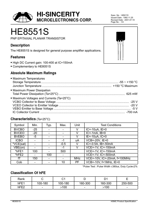
Page No. : 1/4HE8551SPNP EPITAXIAL PLANAR TRANSISTORDescriptionFeatures• High DC Current gain: 100-400 at IC=150mA• Complementary to HE8051SAbsolute Maximum Ratings• Maximum TemperaturesStorage Temperature............................................................................................ -55 ~ +150 °C Junction Temperature................................................................................... +150 °C Maximum • Maximum Power DissipationTotal Power Dissipation (Ta=25°C)............................................................................... 625 mW • Maximum Voltages and Currents (Ta=25°C)VCBO Collector to Base Voltage....................................................................................... -25 V VCEO Collector to Emitter Voltage.................................................................................... -20 V VEBO Emitter to Base Voltage............................................................................................ -5 V IC Collector Current ..................................................................................................... -700 mA Characteristics (Ta=25°C)Symbol Min.Typ.Max.Unit Test ConditionsBVCBO-25--V IC=-10uA, IE=0BVCEO-20--V IC=-1mA, IB=0BVEBO-5--V IE=-10uA, IC=0ICBO---1uA VCB=-20V, IE=0*VCE(sat)---0.5V IC=-0.5A, IB=-50mAVBE(on)---1V VCE=-1V, IC=-150mA*hFE1100-500VCE=-1V, IC=-150mA*hFE2-100-VCE=-1V, IC=-500mAfT150--MHz VCE=-10V, IC=-20mA, f=100MHzCob--10PF VCB=-10V, f=1MHz, IE=0*Pulse Test : Pulse Width ≤380us, Duty Cycle≤2% Classification Of hFERank C C1D D1EhFE1100-180100-180160-300160-300250-500 hFE2->100->100-Page No. : 2/4 Characteristics CurvePage No. : 3/4Page No. : 4/4TO-92 Dimension*:TypicalInches Millimeters Inches Millimeters DIM Min.Max.Min.Max.DIM Min.Max.Min.Max.A 0.17040.1902 4.33 4.83G0.01420.02200.360.56B 0.17040.1902 4.33 4.83H -*0.1000-*2.54C 0.5000-12.70-I -*0.0500-*1.27D 0.01420.02200.360.56α1-*5°-*5°E -*0.0500-*1.27α2-*2°-*2°F0.13230.14803.36 3.76α3-*2°-*2°Notes : 1.Dimension and tolerance based on our Spec. dated Apr. 25,1996.2.Controlling dimension : millimeters.3.Maximum lead thickness includes lead finish thickness, and minimum lead thickness is the minimum thickness of base material.4.If there is any question with packing specification or packing method, please contact your local HSMC sales office.Material :• Lead : 42 Alloy ; solder plating• Mold Compound : Epoxy resin family, flammability solid burning class:UL94V-0Important Notice:• All rights are reserved. Reproduction in whole or in part is prohibited without the prior written approval of HSMC.• HSMC reserves the right to make changes to its products without notice.• HSMC semiconductor products are not warranted to be suitable for use in Life-Support Applications, or systems.• HSMC assumes no liability for any consequence of customer product design, infringement of patents, or application assistance.Head Office And Factory :• Head Office (Hi-Sincerity Microelectronics Corp.) : 10F.,No. 61, Sec. 2, Chung-Shan N. Rd. Taipei Taiwan R.O.C.Tel : 886-2-25212056 Fax : 886-2-25632712, 25368454• Factory 1 : No. 38, Kuang Fu S. Rd., Fu-Kou Hsin-Chu Industrial Park Hsin-Chu Taiwan. R.O.C Tel : 886-3-5983621~5 Fax : 886-3-5982931。
可控硅企业技术标准

Q/WR武汉武整整流器有限公司企业标准Q/JS-BPB027.2012可控硅 企业技术标准武汉武整整流器有限公司部品部发布2014年 04月11日 发布 2012 年 04 月 12 日 实施目录目录⋯⋯⋯⋯⋯⋯⋯⋯⋯⋯⋯⋯⋯⋯⋯⋯⋯⋯⋯⋯⋯⋯⋯⋯⋯⋯⋯⋯⋯⋯⋯⋯⋯⋯⋯⋯⋯⋯⋯⋯⋯⋯Ⅰ使用前言说明⋯⋯⋯⋯⋯⋯⋯⋯⋯⋯⋯⋯⋯⋯⋯⋯⋯⋯⋯⋯⋯⋯⋯⋯⋯⋯⋯⋯⋯⋯⋯⋯⋯⋯⋯⋯⋯⋯Ⅱ标准范围及引用⋯⋯⋯⋯⋯⋯⋯⋯⋯⋯⋯⋯⋯⋯⋯⋯⋯⋯⋯⋯⋯⋯⋯⋯⋯⋯⋯⋯⋯⋯⋯⋯⋯⋯⋯⋯⋯Ⅲ1主体种类说明⋯⋯⋯⋯⋯⋯⋯⋯⋯⋯⋯⋯⋯⋯⋯⋯⋯⋯⋯⋯⋯⋯⋯⋯⋯⋯⋯⋯⋯⋯⋯⋯⋯⋯⋯⋯⋯.1 2使用环境要求⋯⋯⋯⋯⋯⋯⋯⋯⋯⋯⋯⋯⋯⋯⋯⋯⋯⋯⋯⋯⋯⋯⋯⋯⋯⋯⋯⋯⋯⋯⋯⋯⋯⋯⋯⋯⋯.1 3部品外观相关要求⋯⋯⋯⋯⋯⋯⋯⋯⋯⋯⋯⋯⋯⋯⋯⋯⋯⋯⋯⋯⋯⋯⋯⋯⋯⋯⋯⋯⋯⋯⋯⋯⋯⋯⋯.1 4包装、贮存要求⋯⋯⋯⋯⋯⋯⋯⋯⋯⋯⋯⋯⋯⋯⋯⋯⋯⋯⋯⋯⋯⋯⋯⋯⋯⋯⋯⋯⋯⋯⋯⋯⋯⋯⋯⋯.1 4.1包装⋯⋯⋯⋯⋯⋯⋯⋯⋯⋯⋯⋯⋯⋯⋯⋯⋯⋯⋯⋯⋯⋯⋯⋯⋯⋯⋯⋯⋯⋯⋯⋯⋯⋯⋯⋯⋯⋯⋯⋯.1 4.2贮存⋯⋯⋯⋯⋯⋯⋯⋯⋯⋯⋯⋯⋯⋯⋯⋯⋯⋯⋯⋯⋯⋯⋯⋯⋯⋯⋯⋯⋯⋯⋯⋯⋯⋯⋯⋯⋯⋯⋯⋯.1 5阻燃状况要求⋯⋯⋯⋯⋯⋯⋯⋯⋯⋯⋯⋯⋯⋯⋯⋯⋯⋯⋯⋯⋯⋯⋯⋯⋯⋯⋯⋯⋯⋯⋯⋯⋯⋯⋯⋯⋯.1 6部品检测仪器设备的要求⋯⋯⋯⋯⋯⋯⋯⋯⋯⋯⋯⋯⋯⋯⋯⋯⋯⋯⋯⋯⋯⋯⋯⋯⋯⋯⋯⋯⋯⋯⋯⋯.1 7检验规则⋯⋯⋯⋯⋯⋯⋯⋯⋯⋯⋯⋯⋯⋯⋯⋯⋯⋯⋯⋯⋯⋯⋯⋯⋯⋯⋯⋯⋯⋯⋯⋯⋯⋯⋯⋯⋯⋯⋯.2 7.1适用规范⋯⋯⋯⋯⋯⋯⋯⋯⋯⋯⋯⋯⋯⋯⋯⋯⋯⋯⋯⋯⋯⋯⋯⋯⋯⋯⋯⋯⋯⋯⋯⋯⋯⋯⋯⋯⋯⋯.2 7.2检验样品的抽取说明⋯⋯⋯⋯⋯⋯⋯⋯⋯⋯⋯⋯⋯⋯⋯⋯⋯⋯⋯⋯⋯⋯⋯⋯⋯⋯⋯⋯⋯⋯⋯⋯⋯.2 7.3检验结果的判定及处理⋯⋯⋯⋯⋯⋯⋯⋯⋯⋯⋯⋯⋯⋯⋯⋯⋯⋯⋯⋯⋯⋯⋯⋯⋯⋯⋯⋯⋯⋯⋯⋯.2 8部品常规检验要求⋯⋯⋯⋯⋯⋯⋯⋯⋯⋯⋯⋯⋯⋯⋯⋯⋯⋯⋯⋯⋯⋯⋯⋯⋯⋯⋯⋯⋯⋯⋯⋯⋯⋯⋯.2 8.1部品尺寸检验⋯⋯⋯⋯⋯⋯⋯⋯⋯⋯⋯⋯⋯⋯⋯⋯⋯⋯⋯⋯⋯⋯⋯⋯⋯⋯⋯⋯⋯⋯⋯⋯⋯⋯⋯⋯.2 8.2部品基本电性能检测⋯⋯⋯⋯⋯⋯⋯⋯⋯⋯⋯⋯⋯⋯⋯⋯⋯⋯⋯⋯⋯⋯⋯⋯⋯⋯⋯⋯⋯⋯⋯⋯⋯.2 8.2.1阴阳极击穿电压测试⋯⋯⋯⋯⋯⋯⋯⋯⋯⋯⋯⋯⋯⋯⋯⋯⋯⋯⋯⋯⋯⋯⋯⋯⋯⋯⋯⋯⋯⋯⋯⋯.2 8.2.2阴阳极反向漏电流测试⋯⋯⋯⋯⋯⋯⋯⋯⋯⋯⋯⋯⋯⋯⋯⋯⋯⋯⋯⋯⋯⋯⋯⋯⋯⋯⋯⋯⋯⋯⋯.3 8.3可焊性检测⋯⋯⋯⋯⋯⋯⋯⋯⋯⋯⋯⋯⋯⋯⋯⋯⋯⋯⋯⋯⋯⋯⋯⋯⋯⋯⋯⋯⋯⋯⋯⋯⋯⋯⋯⋯⋯ .38.4机械性检测⋯⋯⋯⋯⋯⋯⋯⋯⋯⋯⋯⋯⋯⋯⋯⋯⋯⋯⋯⋯⋯⋯⋯⋯⋯⋯⋯⋯⋯⋯⋯⋯⋯⋯⋯⋯⋯ .38.5标示耐擦性检测⋯⋯⋯⋯⋯⋯⋯⋯⋯⋯⋯⋯⋯⋯⋯⋯⋯⋯⋯⋯⋯⋯⋯⋯⋯⋯⋯⋯⋯⋯⋯⋯⋯⋯⋯ .38.6RoHS 测试⋯⋯⋯⋯⋯⋯⋯⋯⋯⋯⋯⋯⋯⋯⋯⋯⋯⋯⋯⋯⋯⋯⋯⋯⋯⋯⋯⋯⋯⋯⋯⋯⋯⋯⋯⋯⋯ .48.6.1欧盟 ROHS指令限制物质以及含量⋯⋯⋯⋯⋯⋯⋯⋯⋯⋯⋯⋯⋯⋯⋯⋯⋯⋯⋯⋯⋯⋯⋯⋯⋯⋯⋯ 48.6.2测试结果判定⋯⋯⋯⋯⋯⋯⋯⋯⋯⋯⋯⋯⋯⋯⋯⋯⋯⋯⋯⋯⋯⋯⋯⋯⋯⋯⋯⋯⋯⋯⋯⋯⋯⋯⋯.4 9可靠性实验⋯⋯⋯⋯⋯⋯⋯⋯⋯⋯⋯⋯⋯⋯⋯⋯⋯⋯⋯⋯⋯⋯⋯⋯⋯⋯⋯⋯⋯⋯⋯⋯⋯⋯⋯⋯⋯⋯.4 9.1温度冲击⋯⋯⋯⋯⋯⋯⋯⋯⋯⋯⋯⋯⋯⋯⋯⋯⋯⋯⋯⋯⋯⋯⋯⋯⋯⋯⋯⋯⋯⋯⋯⋯⋯⋯⋯⋯⋯⋯.4 9.2高温反偏实验⋯⋯⋯⋯⋯⋯⋯⋯⋯⋯⋯⋯⋯⋯⋯⋯⋯⋯⋯⋯⋯⋯⋯⋯⋯⋯⋯⋯⋯⋯⋯⋯⋯⋯⋯⋯.5 10试产检测项目⋯⋯⋯⋯⋯⋯⋯⋯⋯⋯⋯⋯⋯⋯⋯⋯⋯⋯⋯⋯⋯⋯⋯⋯⋯⋯⋯⋯⋯⋯⋯⋯⋯⋯⋯⋯ .6标准使用前言说明可控硅是我司主要生产元器件,在电源电路起自动控制开关的作用!根据可控硅的承认书和《中华人民共和国标准化法》规定,特制订本企业标作为 IQC 部品来料检验及部品工程认定和组织生产销售的依据。
硅钢产品介绍1
硅钢产品介绍一、硅钢产品的预备知识二、硅钢产品分类及主要性能三、硅钢生产工艺及各工序主要功能四、硅钢产品的主要用途五、对热轧原料的要求一、硅钢产品的基础知识硅钢生产已有近百年的历史,它是制造电机、变压器和镇流器铁芯以及各种电器元件用以节能的最重要的金属功能性材料之一。
硅钢产品,特别是取向硅钢的制造工艺和设备复杂、成分控制严格、制造工序长,而且影响性能的因素多,因此常把取向硅钢产品质量看作是衡量一个国家特殊钢制造技术水平的重要标志,并获得了冶金产品“工艺品”的美称。
1.硅钢产品的分类(见下表):硅钢产品的分类除表中所列的品种类别外,还有一些特殊用途的硅钢产品,如用作中、高频电机和变压器以及脉冲变压器等的0.15和0.20mm厚3%Si冷轧无取向硅钢薄带,及0.025、0.05及0.10厚3%Si冷轧取向硅钢极薄带。
用作继电器和电力开关的0.70mm厚3%Si冷轧无取向硅钢等。
2.对硅钢片性能的要求一般要求电机、变压器和其它电器部件效率高、节能、体积小和重量轻,硅钢片主要是作为电机、变压器铁芯材料,通常是以铁芯损耗和磁感应强度作为产品磁性保证值。
因此对硅钢产品的性能要求如下:2.1铁芯损耗(P T)低●铁芯损耗是指铁芯在≥50H Z交变磁场下磁化时所消耗的无效电能,简称铁损,也称交变损耗,单位为W/kg●硅钢片的铁损(P T)包括磁滞损耗(P h)、涡流损耗(P e)和反常损耗(P a)三部份。
1)磁滞损耗(P h)磁滞损耗是磁性材料在磁化和反磁化过程中,由于材料中的夹杂物、晶体缺陷、内应力和晶体位向等因素阻碍畴壁移动,使磁通变化受阻,造成磁感应强度落后于磁场变化的磁滞现象而引起的能量损耗。
2)涡流损耗(P e):涡流损耗是磁性材料在交变磁化过程中,在磁通改变方向时,按照法拉弟电磁感应法则,在磁通周围感生出局部电动势而引起涡电流所造成的能量损耗。
3)反常损耗(P a):反常损耗是材料磁化时,由于磁畴结构不同而引起的能量损耗。
Eaton 198528 商品说明书

Eaton 198528Eaton Moeller® series Rapid Link - DOL starter, 6.6 A, Sensorinput 2, Actuator output 1, 400/480 V AC, AS-Interface®, S-7.4 for31 modules, HAN Q5Allgemeine spezifikationEaton Moeller® series Rapid Link DOLstarter198528120 mm270 mm220 mm1.64 kg UL 60947-4-2CEIEC/EN 60947-4-2RoHSUL approvalCCCAssigned motor rating: for normal internally and externally ventilated 4 pole, three-phase asynchronous motors with 1500 rpm at 50 Hz or 1800 min at 60 Hz 4015081964031RAMO5-D214A31-5120S1Product Name Catalog NumberProduct Length/Depth Product Height Product Width Product Weight CertificationsCatalog Notes EANModel CodeParameterization: drivesConnectDiagnostics and reset on device and via AS-Interface Parameterization: KeypadParameterization: FieldbusParameterization: drivesConnect mobile (App)Short-circuit releaseThermo-clickKey switch position HANDElectronic motor protectionTwo sensor inputs through M12 sockets (max. 150 mA) for quick stop and interlocked manual operation1 Actuator outputKey switch position AUTOKey switch position OFF/RESETThermistor monitoring PTCTemperature compensated overload protectionFor actuation of motors with mechanical brakeExternal reset possible CLASS 10 ANEMA 12IP65Class A10,000,000 Operations (at AC-3)10,000,000 Operations (at AC-3)Direct starter0.3 A6.6 AIIIMotor starterAS-Interface profile cable: S-7.4 for 31 modulesASI4000 VAC voltageCenter-point earthed star network (TN-S network) Phase-earthed AC supply systems are not permitted.DOL starterDCFeatures Fitted with: Functions ClassDegree of protectionElectromagnetic compatibility Lifespan, electricalLifespan, mechanicalModelOverload release current setting - min Overload release current setting - max Overvoltage categoryProduct categoryProtocolRated impulse withstand voltage (Uimp) System configuration typeTypeVoltage typeVertical15 g, Mechanical, According to IEC/EN 60068-2-27, 11 ms, Half-sinusoidal shock 11 ms, 1000 shocks per shaftResistance: 10 - 150 Hz, Oscillation frequencyResistance: 57 Hz, Amplitude transition frequency on accelerationResistance: 6 Hz, Amplitude 0.15 mmResistance: According to IEC/EN 60068-2-6Above 1000 m with 1 % performance reduction per 100 m Max. 2000 mMax. 1000 m-10 °C55 °C-40 °C70 °C< 95 %, no condensationIn accordance with IEC/EN 50178Adjustable, motor, main circuit0.3 - 6.6 A, motor, main circuit6.6 A (at 150 % Overload)Maximum of one time every 60 seconds 380 - 480 V (-15 %/+10 %, at 50/60 Hz) 20 - 35 ms20 - 35 ms50/60 HzAC-53a 3 HP≤ 0.6 A (max. 6 A for 120 ms), Actuator for external motor brake400/480 V AC -15 % / +10 %, Actuator for external motor brake10 kA0 AType 1 coordination via the power bus' feeder unit, Main circuitMounting position Shock resistance Vibration AltitudeAmbient operating temperature - min Ambient operating temperature - max Ambient storage temperature - min Ambient storage temperature - max Climatic proofingCurrent limitationInput currentMains switch-on frequency Mains voltage tolerance Off-delayOn-delayOutput frequency Overload cycleRated frequency - min Assigned motor power at 460/480 V, 60 Hz, 3-phaseBraking currentBraking voltageRated conditional short-circuit current (Iq)Rated conditional short-circuit current (Iq), type 2, 380 V, 400 V, 415 VShort-circuit protection (external output circuits)47 Hz63 Hz6.6 A6.6 A0.09 kW3 kW0 kW3 kW400 V AC, 3-phase 480 V AC, 3-phase 50/60 Hz, fLN, Main circuit AC voltageCenter-point earthed star network (TN-S network) Phase-earthed AC supply systems are not permitted.0 V0 V0 V0 V0 V0 V400/480 V AC (external brake 50/60 Hz)24 V DC (-15 %/+20 %, external via AS-Interface® plug)Connections pluggable in power section Number of slave addresses: 31 (AS-Interface®)Max. total power consumption from AS-Interface® power supply unit (30 V): 190 mASpecification: S-7.4 (AS-Interface®)110 m, Radio interference level, maximum motor cable lengthMeets the product standard's requirements.Meets the product standard's requirements.Rated frequency - max Rated operational current (Ie) at 150% overload Rated operational current (Ie) at AC-3, 380 V, 400 V, 415 V Rated operational power at 380/400 V, 50 Hz - min Rated operational power at 380/400 V, 50 Hz - max Rated operational power at AC-3, 220/230 V, 50 Hz Rated operational power at AC-3, 380/400 V, 50 Hz Rated operational voltage Supply frequencySystem configuration type Rated control supply voltage (Us) at AC, 50 Hz - min Rated control supply voltage (Us) at AC, 50 Hz - max Rated control supply voltage (Us) at AC, 60 Hz - min Rated control supply voltage (Us) at AC, 60 Hz - max Rated control supply voltage (Us) at DC - min Rated control supply voltage (Us) at DC - max Rated control voltage (Uc)ConnectionInterfacesNumber of auxiliary contacts (normally closed contacts)Number of auxiliary contacts (normally open contacts)Cable length10.2.2 Corrosion resistance10.2.3.1 Verification of thermal stability of enclosuresMeets the product standard's requirements.Meets the product standard's requirements.Meets the product standard's requirements.Does not apply, since the entire switchgear needs to be evaluated.Does not apply, since the entire switchgear needs to be evaluated.Meets the product standard's requirements.Does not apply, since the entire switchgear needs to be evaluated.Meets the product standard's requirements.Does not apply, since the entire switchgear needs to be evaluated.Does not apply, since the entire switchgear needs to be evaluated.Is the panel builder's responsibility.Is the panel builder's responsibility.Is the panel builder's responsibility.Is the panel builder's responsibility.Is the panel builder's responsibility.The panel builder is responsible for the temperature rise Generation Change RASP4 to RASP5Generation change from RA-SP to RASP 4.0Firmware Update RASP 4.0Generationentausch RAMO4 zu RAMO5Generation Change RA-SP to RASP5Elektromagnetische Verträglichkeit (EMV)Configuration to Rockwell PLC Rapid Link 5Configuration to Rockwell PLC for Rapid LinkGeneration change RAMO4 to RAMO5Generationentausch RA-MO zu RAMO4.0 Generationswechsel RASP4 zu RASP5Generationenwechsel RA-SP zu RASP5Anschluss von Frequenzumrichtern an GeneratornetzeGeneration change from RA-MO to RAMO 4.0 Generationentausch RA-SP zu RASP4.0MN040003_DEMN034004_DERapid Link 5 - brochureDA-SW-USB Driver PC Cable DX-CBL-PC-1M5DA-SW-drivesConnect - InstallationshilfeDA-SW-drivesConnectDA-SW-USB Driver DX-COM-STICK3-KITDA-SW-drivesConnect - installation helpDA-SW-Driver DX-CBL-PC-3M0Material handling applications - airports, warehouses and intra-logisticsETN.RAMO5-D214A31-5120S1.edzIL034084ZUDE | Rapid Link 5Sortimentskatalog Antriebstechnik-DE10.2.3.2 Verification of resistance of insulating materials to normal heat10.2.3.3 Resist. of insul. mat. to abnormal heat/fire by internal elect. effects10.2.4 Resistance to ultra-violet (UV) radiation10.2.5 Lifting10.2.6 Mechanical impact10.2.7 Inscriptions10.3 Degree of protection of assemblies10.4 Clearances and creepage distances10.5 Protection against electric shock10.6 Incorporation of switching devices and components10.7 Internal electrical circuits and connections10.8 Connections for external conductors10.9.2 Power-frequency electric strength10.9.3 Impulse withstand voltage10.9.4 Testing of enclosures made of insulating material10.10 Temperature rise Anmerkungen zur AnwendungBenutzerhandbücherBroschüreneCAD model Installationsanleitung InstallationsvideosKatalogeEaton Konzern plc Eaton-Haus30 Pembroke-Straße Dublin 4, Irland © 2023 Eaton. Alle Rechte vorbehalten. Eaton ist eine eingetrageneMarke.Alle anderen Warenzeichen sindEigentum ihrer jeweiligenBesitzer./socialmediacalculation. Eaton will provide heat dissipation data for thedevices.Is the panel builder's responsibility. The specifications for the switchgear must be observed.Is the panel builder's responsibility. The specifications for the switchgear must be observed.The device meets the requirements, provided the information in the instruction leaflet (IL) is observed.ramo5_v2.stpramo5_v2.dwgeaton-bus-adapter-rapidlink-speed-controller-dimensions-003.eps eaton-bus-adapter-rapidlink-speed-controller-dimensions-002.eps eaton-bus-adapter-rapidlink-reversing-starter-dimensions-002.eps eaton-bus-adapter-rapidlink-reversing-starter-dimensions.eps10.11 Short-circuit rating10.12 Electromagnetic compatibility 10.13 Mechanical function mCAD model Zeichnungen。
巴鲁夫 工业 RFID系统 产品手册说明书

Industrial RFID systems MANAGING ALL YOUR DATABalluff offers you a wide selection of data carriers and read/write heads for LF, HF and UHF applications. With the BIS V multi-frequency processor unit, all systems can be combined with each other. This adds flexibility and saves costs through lower inventory levels.Industrial RFID systems – managing all your dataAutomatic identification and tracking in productionTHE PERFORMANCE RANGEYour Balluff solutionsn HF RFID system (13.56 MHz) BIS M n LF RFID system (70/455 kHz) BIS C n LF RFID system (125 kHz) BIS L n UHF RFID system (860/960 MHz) BIS UGo online to individually configure your own system www.balluff.de/go/rfid-configuratorIO-LINK ALL-IN-ONE BIS V PROCESSOR UNIT1 Network block2 Read/write heads with IO-Link3 Data carriers4 Read/write heads with integrated processor unit5 Universal processor unit6 Read/write heads2266433315UHF by country-specific frequencies1 South Korea LF: 125 kHz HF: 13.56 MHzUHF: 917...920.8 MHz 2 JapanLF: 125 kHz HF: 13.56 MHzUHF: 916.7...920.8 MHz 3 ChinaLF: 125 kHz HF: 13.56 MHzUHF: 840.5...844.5 MHz 4 AustraliaLF: 125 kHz HF: 13.56 MHz UHF: 920...926 MHz5 South Africa LF: 125 kHz HF: 13.56 MHzUHF: 865.6...867.6 MHz 6 EuropeLF: 125 kHz HF: 13.56 MHzUHF: 865.6...867.6 MHz 7 USA/Canada/Mexico LF: 125 kHz HF: 13.56 MHz UHF: 902...928 MHz 8 BrazilLF: 125 kHz HF: 13.56 MHzUHF: 902...907.5 MHzWHAT ARE THECONSEQUENCES OF THE DIFFERENT FREQUENCIES?Briefly stated, different frequencies mean different working ranges, since the frequency determines the range. The frequency also affects the coupling behavior (see: How the system components communicate).LF is best suited for close range and for difficult conditions such as metallic surroundings. LF is therefore often used in tool identification.HF is ideal for parts tracking at close range up to 400 mm. With HF you can process and store larger quantities of data at high transmission speeds.UHF typically communicates at a range of 6 m distance. UHF allows simultaneous reading of multiple data carriers (multi-tagging).System frequenciesWorking range of the Balluff BIS RFID systemsSYSTEM STRUCTURERFID requires three main components. These form an RFID system:–■Data carrier (data storage)–■Read/write head (data transmission)–■Processor unit (data processing and communication)The system components in detail–■Data carrier (Tag/Data Carrier)Stores all kinds of data which is read or written by computers or automation equipment. The data carrier antenna sends and receives the signals. Read/write versions are available in various memory capacities and with various storage mechanisms.– Passive data carriers: without power supply – Active data carriers: with power supply–■Read/write headProvides power to the data carrier, reads its data and writes new data to it. It sends this data to the processor unit where the data is further processed. –■AntennaTransmits the power.– HF-/LF systems: Antenna is integrated in the read/write head– UHF systems: Usually passive antennas without read/write head electronics (integrated into the processor unit).–■Processor unitUsed for signal processing and preparation. It typically includes an integrated interface for connecting to the controller/PC system.UHF system: The read/write function can be integrated into the processor unit, so that only a passive antenna and the data carrier are required.How the system components communicateThe data carrier and read/write head connect via the frequency-dependent coupling.With UHF the coupling is via electromagnetic waves, and for LF and HF the coupling is inductive.Components of a HF/LF systemData carrier Read/write head Processor unitUsed at close range, the data carrier must be placed exactly within the read range of the read/write head.Components of a UHF systemData carrier Antenna withProcessor unitread/write head electronicsData carrier Passive antennaProcessor unit withread/write head electronicsIn UHF systems close placement of the data carrier in front of the antenna is not necessary because of the large working range. Still, there are a few rules (see: What to know about UHF systems).Various industry standards are in place both for theLF/HF range and for UHF for communication between the system components. These specify how the information is transmitted. There are also proprietary manufacturer-specific solutions available (see: What you need to know about LF/HF systems/UHF systems).SYSTEM CHARACTERISTICSWhy data storage is importantSelection of the data storage determines where data can be processed and with which components. You can use either of two storage concepts: the central database and decentralized data retention.Central data storage–■All data records are stored in a central database –■Data carrier is simply an identifier –■Mainly for reading informationCan be LF, HF or UHF systems, but mainly used with UHF systemsDecentralized data retention–■All data records are stored on data carriers –■The data carrier stores the identifier and all data records (no central database)–■For both reading and writing informationMainly used with HF/LF systemsWHAT YOU NEED TO KNOW ABOUT LF/HF SYSTEMSIn brief, the read/write distance in LF/HF systems is affected by the antenna shape and the traverse speed.When installing the data carriers the installation conditions and close proximity of metal play a role.Antenna shapeData carriers and read/write heads are constructedwith a rod or round antenna. To achieve the best results the antenna shape must be identical to that of the read/write head. This means: Use rod antenna with rod antenna or round antenna with round antenna.The antenna shape determines different field distributions and read distances. It also determines the active communication field.Ideal working rangeRound antenna–■The lobe of the antenna field is distributed evenly and symmetrically–■No polarization or directionality, even offset.This means the data carrier and read/write head Rod antenna–■The lobe of the antenna field is distributed unevenly and has additional sidelobes–■The is polarization and directionality, which allows greater read distances than with a round antenna–■Identical orientation of the data carrier and read/write head is important in order to achieve greater read distancesInstalling data carriersAccount for distance to metalTo reach the specified read/write distance, a data carrier in a metallic environment must be mounted at a certain distance from metal and within a certain metal-free clear zone. The exact specifications can be found in the data sheets. The following distinctions are made:–■Flush in metalThe sensing surface can be mounted flush on the surface of steel so that it is even with adjacent areas. The range here is less than for differently constructed/installed data carriers of the same size.–■On metalThe sensing surface must not be in contact or surrounded by steel.–■Metal-free (clear zone)The entire area of the data carrier must be kept clear of any type of metal.12365874Data carriers with various memory types are available Traditional memory chips are EEPROM and FRAM.Both types use inductive coupling for power supply and data transmission. They differ in the maximum number of write cycles.–■EEPROM (Electrical erasable programmableread only memory): 100,000 to 1,000,000 write cycles –■FRAM (Ferro-electrical random access memory): 1010 write cyclesHow traverse speed, read/write distance and data transmission time relate to each otherFor reliable data transfer between read/write head andDynamic read/write modeThe data carrier passes by the read/write head without stopping. This should be as close as possible to achieve a long read/write path.How to calculate the traverse speed for dynamic applications Traverse speed (v)Offset (s)=At least 315 mm of offset is required to read the data within a dwell time of 45 ms. Assuming the maximum offset is 340 mm, the read distance must be configured to be very short. The greater the offset of the read/write head, the greater the distance between data carrier and read/write head can be.Important industry standards–■ISO 15693International series of standards for non-contacting chip cards, identification systems and access controls. Operates at a frequency of 13.56 MHz and is the prevailing standard in automation.ISO 15693 defines the protocols for communication between data carrier and read/write head. The datacarriers and read/write heads from different suppliers are generally compatible if they adhere to the same standard. –■ISO 14443International series of standards for non-contact chipcards. These are used in identification systems and access controlling, but also for payment applications such as credit cards, public transportation tickets, etc. Operates at a frequency of 13.56 MHz.In contrast to the ISO 15693 standard, ISO 14443specifies that the data carrier and read/write head carry a manufacturer-specific identifier. Only if the identifiers agree can they communicate with each other.Balluff uses the most commonly accepted contactless chip technology NXP Mifare. This complies with ISO-Standards ISO 7816 and ISO 14443A.High performance solutions from BalluffIn addition to the industry standards there are proprietary systems that are not described by any standard. For example, high-performance solutions from Balluff that are faster and process more data than these industry standards allow. Here the following components are used:–■High-memory data carriers: Data carriers with a memory capacity > 8 kilobytes.–■High-speed data carriers: Combined with the associated read/write heads you can achieve up to eight times greater read speeds than applications that fall under DIN ISO 15693.WHAT YOU NEED TO KNOW ABOUT UHF SYSTEMSPower transmission between data carrier and read/write head is essential for optimal function of a UHF RFID system. Whether and how the antennas need to be aligned with each other depends on the type of polarization of the antennas.Relationship between antenna polarization and data carrier orientationThe polarization of a UHF antenna is determined by the direction of the electrical field of the wave.–■Linear polarized antennasThe electrical field runs either vertical or horizontal to be identically aligned in order to transmit power.–■Data carrier antennaIn UHF systems the coupling is electromagnetic. To transmit data the data carrier‘s antenna converts electromagnetic waves and high-frequency alternating current into each other. Here the polarization direction of the sending antenna and the orientation of the data carrier must be selected correctly. (See illustration for how to achieve optimal power transmission).Construction of a UHF data carrierUHF data carriers with a dipole antenna are often selected (see illustration above). Many other antenna shapes are available as well. These offer particular properties and determine the form factor of the data carrier.Other form factors for UHF data carriersTypical UHF industry standards–■ISO/IEC 18000-6:2013International series of standards that provide the general description of the air interface and signal transmission. The latest standard ISO 18000-63 was published in 2015.–■EPC Class1 Gen2Was published by the standardization organization EPC global, which develops voluntary standards. EPC Class 1 Gen2 Version 2.0.1 is fully compatible with ISO 18000-63.This compatibility mans you can use the same hardware infrastructure and the same data carriers both in an ISO standard environment and an EPC environment.Both standards are suitable for worldwide use. You must however take note of the various national RF regulations.UHF antenna field requires specific test scenariosIn brief: Since the surroundings affect the antenna field, you must perform the closest possible simulation of the ambient conditions.The UHF antenna beams its signal in a wide opening angle. Undesired reflections and absorption in a UHF RFID system Typical ideal antenna fieldin overlapping of wavetrains. Overall it can result in local fields with higher and lower field strengths, or even field collapses (read holes).If a data carrier finds itself in such a read hole, it can no longer communicate with the read/write head.Headquarters Balluff GmbHSchurwaldstrasse 973765 Neuhausen a. d. F.GermanyPhone +49 7158 173-0Fax +49 7158 5010******************D o c . n o . 949747E N · I 20 · S u b j e c t t o c h a n g e s .CONTACT OUR WORLDWIDE SUBSIDIARIES。
- 1、下载文档前请自行甄别文档内容的完整性,平台不提供额外的编辑、内容补充、找答案等附加服务。
- 2、"仅部分预览"的文档,不可在线预览部分如存在完整性等问题,可反馈申请退款(可完整预览的文档不适用该条件!)。
- 3、如文档侵犯您的权益,请联系客服反馈,我们会尽快为您处理(人工客服工作时间:9:00-18:30)。
-1Total 9 Pages
8/8/2006
元器件交易网
BL8555
Selection Guide BL8555 XX X X Pin Assignment
:
Pin Description Pin Number SOT-23-5A Symbol SOT-23-5B Function
SC-70-5
Product Classification Output Voltage
1.2V 1.5V 1.8V 2.1V 2.5V 2.8V 3.0V 3.2V 3.3V 3.5V
Package Type
SOT-23-5A SOT-23-5A SOT-23-5A SOT-23-5A SOT-23-5A SOT-23-5A SOT-23-5A SOT-23-5A SOT-23-5A SOT-23-5A
Typical Application Circuit
Application hints
Explanation
-5Total 9 Pages
8/8/2006
元器件交易网
BL8555
Typical Performance Characteristics 1) Output Voltage vs. Output Current (with output short protection) 2) Output Voltage vs. Input Voltage
Type I
Type II
-8Total 9 Pages
8/8/2006
元器件交易网
BL8555
-9Total 9 Pages
8/8/2006
SOT-23-5B SOT-23-5B SOT-23-5B SOT-23-5B SOT-23-5B SOT-23-5B SOT-23-5B SOT-23-5B SOT-23-5B SOT-23-5B
Product Name
BL8555-12PRB BL8555-15PRB BL8555-18PRB BL8555-21PRB BL8555-25PRB BL8555-28PRB BL8555-30PRB BL8555-32PRB BL8555-33PRB BL8555-35PRB
Vout T Vout
-4Total 9 Pages
8/8/2006
元器件交易网
BL8555
Electrical Characteristics by Output Voltage Output Voltage Vout (V) Dropout Voltage, VDIF (V) Condition Typ. Max.
Item Min Recommended Max unit
Electrical Characteristics
BL8555, for arbitrary output voltage
Symbol
Parameter
Conditions
Min
Typ
Max
Units
Vout Vin Vout Vout Iout
SC-70-5 SOT23-5A SOT23-5B
Block Diagram
-3Total 9 Pages
8/8/2006
元器件交易网
BL8555
Absolute Maximum Ratings
Recommended Work Conditions
元器件交易网
BL8555
Low noise 150mA LDO regulator Features General Description
Applications
BL8555 Typical Application Circuit
BL8555 Typical Performance Characteristics
Product Name
BL8555-12PRA BL8555-15PRA BL8555-18PRA BL8555-21PRA BL8555-25PRA BL8555-28PRA BL8555-30PRA BL8555-32PRA BL8555-33PRA BL8555-35PRA
Package Type
Package Type
SC-70-5 SC-70-5 SC-70-5 SC-70-5 SC-70-5 SC-70-5 SC-70-5 SC-70-5 SC-70-5 SC-70-5
Product Name
BL8555-12PQ BL8555-15PQ BL8555-18PQ BL8555-21PQ BL8555-25PQ BL8555-28PQ BL8555-30PQ BL8555-32PQ BL8555-33PQ BL8555-35PQ
3) Dropout Voltage vs. Output Current
4) Supply Current vs. Input Voltage
-6Total 9 Pages
8/2006
元器件交易网
BL8555
5) Ripple rejection vs. Frequency 6) Line transient response
Vin
Vout
7) Load transient response
Vout
Iout = 100mA Iout = 50mA
-7Total 9 Pages
8/8/2006
元器件交易网
BL8555
Package Information:
5.0V
SOT-23-5A
BL8555-50PRA
SOT-23-5B
BL8555-50PRB
SC-70-5
BL8555-50PQ
8/8/2006
-2Total 9 Pages
元器件交易网
BL8555
Product Marking information: