模拟块规用户手册501512_Analogue_Block_Gauge_Manual
MITSUBISHI CC-Link数字模拟变换模块 用户说明书

! 危险
表示错误操作可能造成灾难性后果 引起死亡或重伤事故
! 小心
表示错误操作可能造成危险后果 引起人员轻伤 中度伤害或财产 损失
注意根据情况不同 ! 小心这一级也能引发严重后果 因此一定要遵守以上两级对人员安全非常重要的注意事项
请仔细保管本手册 把它放在最终使用者易于取阅的地方
[设计注意事项]
! 危险
[接线注意事项] ! 小心
在开始安装 接线或其它工作之前 必须断开外部所有相的电源 不这样做可能会损坏产品或出现故障 必须把 FG 端子接到保护接地导线上再接地 不这样做可能导致故障 在确认了产品的额定电压和端子接线正确无误之后再为模块正确接线 不这样做可能导致火灾或失效 一定要在规定扭矩范围内紧固端子螺钉 如果没有拧紧可能导致短路或故障 如果拧得过紧可能由于损坏螺钉或模块而导致短路或故障 一定不要让异物 如碎片或接线头 进入模块 异物进入模块可能导致火灾 失效或故障
在符合本手册中规定的一般操作环境规格下使用 PLC 在不符合本手册中规定的一般操作环境规格下使用 PLC 时 可能会引起电击 火灾 故障 并 会损坏模块 或使模块性能变差 把模块紧固到 DIN 导轨上 或用安装螺钉紧固 但要在规定扭矩范围内拧紧安装螺钉 如果没有拧紧可能导致跌落或故障 如果拧得过紧可能由于损坏螺钉或模块而导致跌落或故障 不要触摸模块的导电区或电器部件 这样做可能导致模块故障或断裂
ቤተ መጻሕፍቲ ባይዱ
本手册阐述了MELSECNET/10网络系统(PC-to-PC网络)的系统配置,特点,功能,设置和
编程。
MELSECNET/10网络系统(远程I/O网络)
SH(NA)-080214C
本手册阐述了MELSECNET/10网络系统的配置,操作特性,功能,设置和编程。
Statox 501 PID传感器头用户指南说明书

Statox 501 PID Sensor Headno ATEXStatox 501 PID Sensor HeadOperation Instructions1SAFETY ADVICE 32INTRODUCTION 3 2.1Measuring principle 3 2.2Operation mode 3 2.3Different models 43DRILLING PLAN, DIMENSIONS, CONSTRUCTION, SCOPE OF DELIVERY 44INSTALLATION AND ELECTRICAL CONNECTION 5 4.1Caution 5 4.2Installation 5 4.3Electrical connection 5 5START UP AND MEASURING MODE 6 6CALIBRATION WITH GAS 77TROUBLESHOOTING 88MAINTENANCE / REPLACEMENT OF CONSUMABLES 8 8.1Lamp cleaning / replacement of consumables 98.1.1Removing the sensor 98.1.2Polishing the lamp 108.1.3Electrode stack and lamp replacement 108.1.4Assembly and installation of the sensor 10 8.2Sensor replacement 11 8.3Replacing the filter membrane inside the sensor protection cap 11 8.4Maintenance and cleaning of the sensor head housing 11 9SPARE PARTS AND ACCESSORIES 12 10TECHNICAL DATA 1211DECLARATION OF CONFORMITY 13 231 Safety adviceThe following safety guidelines must be observed in particular:∙ Read and observe this manual.∙ This Statox 501 PID version is not safe to be used in explosive areas!∙ Please observe precautions for handling electrostatic sensitive devices during sensor replacement. ∙ The interface is exclusively designed to operate MiniPID sensors with unfilled solder well. For details see chapter 10: Technical Data.∙ The retaining nut must be fastened at all time. It may only be removed for sensor replacement or maintenance.∙ While connecting the sensor head to the signal cable, power must be off.∙ The sensor head may only be operated within the specified environmental conditions. ∙ Damaged or not tightly closed housings may cause malfunction or loss of accuracy.2 IntroductionThe intended use is the measurement of VOC (Volatile Organic Compounds).2.1 Measuring principleThe target gas passes a membrane and enters the measuring chamber, where it is ionized by a high – energy UV lamp. This produces ions, which are discharged at the electrodes. The discharge currentproduced depends on the number of molecules entering, i.e. the concentration.A PID will detect all substances with an ionization potential smaller than < 10.6 eV. Non detectable, and also not interfering are O 2, N 2, CO, CO 2 and CH 4. Very high humidity will quench the signal.For calibration use Isobutene as reference gas (see chapter 6).2.2 Operation modeThe Statox 501 PID sensor head operates in the diffusion mode.If you want to operate the Statox 501 PID in the flow mode, please contact your Compur Monitors expert.4 2.3 Different modelsThe parameters of the Statox 501 PID interface are set ex works to the requirements of your application. Target gas and measuring range are hardware programmed and noted on the type plate.The sensor type is labeled on the sensor:PID-A1 or MP3SM6FC = ppm Sensor, PID-AH or MP3SB6FC = ppb Sensor.It is important to know which sensor type is in use, in case you need to order spare parts or consumables (see chapter 9).3 Drilling plan, dimensions, construction, scope of delivery1 Grounding contact2 Mounting drill holes for Ф 4 mm bolts3 Aluminum housing4 Cable gland for cable Ф 6-11 mm5 Magnetic pin6 Blind plug7 Plastic tool to open sensor8 Sensor protection cap with gas access through filter membrane9 Nut holding the protection cap 10 Hall sensor, contact area for the magnetic pin 11 LED 12 Interface 13 2 bridges for 3-wire operation (to be installed on the Statox Control Module)Function of the blind plug:∙ The thinner end is a magnetic pin, triggering the internal hall sensor. Hold it close to the contact area on the interface housing to enter the calibration routine.∙ The bigger end can be used to seal the sensor head, once the sensor has been removed for service.4 56712 134 Installation and electrical connection4.1 CautionThe sensor head must be protected from mechanical damage and from ambient conditions outside its specifications. Mount it to the wall at a location where it is easily accessible for service.Place the sensor head close to potential gas leaks considering the specific gravity of the target gas, when selecting the installation level.Position: gas access downwards (+ / - 15° ).Use a shielded cable to transmit the signal to the Statox 501 control module. The sensor head housing must be grounded. Observe local regulations for electrical installations.4.2 InstallationThe housing has two pocket holes for wall installation. You need two screws Ø 4mm.4.3 Electrical connectionRecommended cable: 3 x or 5 x 0,75 mm², with dense-mashed shield. Outer diameter ca. 6 mm(e.g. type Oelflex 415 CP3 X 0.75).The Statox 501 PID sensor head can be operated in the 3–wire or 5–wire mode.Select 3-wire mode if the electrical resistance of the cable loop is < 5 Ω.Select 5-wire mode if the electrical resistance of the cable loop is ≥ 5 Ω. In this mode the two additional …sense“ leads measure the voltage directly on the sensor head and the control module compensates for the voltage drop in the cable.If there are high potential differences in your plant, ground the shield only on the Control Module side. The Statox 501 PID needs a Statox 502 or 503 Control Module for operation. Select the appropriate program prior to connecting the sensor head (if the couple sensor head / control module does not have an ex-works calibration).For this purpose, observe the manual of the control module and the corresponding program listing (programs 80 - 83).Selecting the wrong program might destroy the sensor or cause malfunction!If you have purchased an ex-works calibration sensor head plus control module, the devices are labeled as calibrated pairwise. In this case do not change the program of the control module! Otherwise, the calibration parameters will be lost! Ex-works-calibrated components do have labels with all relevant information on them.If you want to form group alarms, you can operate a Statox 502/503 control module in the common alarm mode. For more information read the manual of the control module.Connecting the interface:565-wire mode 3-wire modeElectrical connections for Statox 501 PID sensor heads to Statox 502/503 control modules. Faulty connection may destroy the interface!5 Start up and measuring mode∙ When connected to power, the LED is flashing green / red alternatingly. ∙ Steady green light indicates the sensor head is in the measuring mode.∙ After start up, allow 30 min warm up time. Then perform a calibration. The calibration can beneglected if an ex-works calibration sensor head and its control module has been purchased. In this case the devices are labeled pairwise.∙ To enter or exit the calibration mode hold the magnetic pin on to the contact area on the type plate. ∙ After any change of program or change of control module a calibration is mandatory.Different modes of operation:Netzteil Statox 502/503 Statox 502/5036 Calibration with gasA calibration can only be performed together with a Statox 502 or 503 Control Module (linecalibration). After an ex-works linecalibration, the mated devices are labeled pairwise.A calibration is required∙after installation (other than ex-works line calibration)∙after replacement of the control module∙after changing the program∙after sensor replacement∙in time intervals as required by local regulations.Before calibrating, allow 30 min warm up time.Calibration to liquid substances in the field is labor intensive and prone to error. Use Isobutene as reference gas and apply the response factors (noted on the type plate) provided by Compur Monitors. The tools required for calibration are: span gas in appropriate concentration, a regulator and a gas adapter.The interface will accept set points between 10 and 100 % of the end of scale value.To achieve best accuracy Compur Monitors recommends to calibrate at the desired alarm threshold value. Calculate the most suitable span gas concentration with this formula:Procedure:∙Hold the magnetic pin on to the contact area to start the calibration routine. The green LED will start flashing. If there is no further activity, the sensor head will automatically return to the measuring mode after 30 minutes.∙Enter the menu “CALIB. ROUTINE” on the Control Module. Adjust zero.∙Connect the gas tube to one of the fittings of the gas adapter. If you want to avoid gas emissions, you may connect an active carbon filter to the outlet. (Art.no. 806 488) Do not bend or twist the tube to avoid overpressure in the gas adapter.∙As soon as the Control Module displays …APPLY SPAN GAS“, connect the gas adapter to the sensor and open the valve. Press …Enter“. The recommend flow is 20 l/h (300 ml/min).∙As soon as …CAL IB. FINISHED“ is displayed, press …Enter“ again.∙Now enter the product of span gas concentration multiplied by the response factor.In case the sensor signal is too low, you will get the message …GAS CONC ERROR“or “CALIBR.FAILED” on the Control Module. Proceed as described in the next chapter.∙Remove the gas adapter and switch the gas off.∙Leave the calibration menu on the Control Module.∙Touch the contact area on the PID with the magnetic pin to enter the measuring mode. The LED should be green then.77 TroubleshootingThe LED going off and the Control Module displaying Err 5, may have the following reasons:∙Sensor missing∙Incorrect wiring∙The voltage at the terminals 1/2 and 4/5 is < 4.6 V. Check the program.∙Sensor defective∙Interface defective.If calibration is not possible(Control Module displays “GAS CONC ERROR“ or “CALIBR. FAILED” after entering the gas concentration), follow this procedure:∙Check if there is enough gas in the cylinder. Is the regulator open? Is the tube free?∙Check the filter membrane for proper gas access.∙Polish the sensor lamp (see 8.1).∙Replace the lamp (see 8.1).∙Replace the electrode pack (see 8.1).∙Check the voltage at the terminals 1/2 and 4/5. It must be > 4.6 V.∙Replace the sensor (see 8.2).If all this does not help, call Compur Monitors technical service.8 Maintenance / Replacement of consumablesA PID sensor will gradually loose sensitivity over time. This process depends on the ambient conditions and the target gas. Therefore, regular calibration, lamp cleaning and replacement of consumables is necessary to guaranty accurate measurement. Compur Monitors recommends to hold stock of consumables.Terms of warrantyPID sensor electronics: 12 months after delivery date. The delivery date is declared as “QC week/year” on the sensor label.No warranty on consumables such as sensor lamps and electrodes.Observe the general precautions for handling electrostatic voltage sensitive electronic components and breakable glass.It is safe to install and remove the sensor while the sensor head is connected to the control module.898.1 Lamp cleaning / replacement of consumables8.1.1 Removing the sensorPlace the sensor on clean soft cloth, pins upward.Insert the plastic pliers into the two ports on the sensor and press until you hear a click.10 8.1.2 Polishing the lamp8.1.3 Electrode stack and lamp replacement∙ Make sure to select the correct spare parts (ppm- or ppb-version)! The ppb - electrode stack is white, the ppm - electrode stack is blue.∙ Do not touch the front side of the lamp or the metallic parts of the electrodes.8.1.4 Assembly and installation of the sensorPull the lamp carefully out of the electrode stack. Never touch its polished front side.Polish the front side with a cotton swap and the polishing powder. Apply tender pressure until you hear a silent squeak. Remove loose polishparticles with a fresh swap until the lamp front is absolutely clean.Push the lamp slightly rotating into the O - ring up to the stop.The lamp must flush with the electrode.∙ To restart the sensor head, push the …Enter“ - button on the Control Module. ∙ After any opening of the sensor, a calibration is mandatory.8.2 Sensor replacementObserve the general precautions for handling electrostatic voltage sensitive electronic components!∙ Make sure to select the correct spare parts. The sensor article codes are marked on its type plate: PID-A1 or MP3SM6FC = ppm sensor, PID-AH or MP3SB6FC = ppb sensor. ∙ Observe chapter 8.1.1 and 8.1.4 for removing or installing the sensor.8.3 Replacing the filter membrane inside the sensor protection cap∙ The gas access opening is protected from dust and humidity intrusion by a Teflon membrane. Whenever the membrane has been damaged or polluted, it must be replaced. (Art. No. 511206). ∙ Remove the clamping ring using a small screw driver. Install a new membrane and clamp ring by pressing both in their position.8.4 Maintenance and cleaning of the sensor head housing∙ Clean the sensor head with a damp cloth. Do not use detergents or solvents. No high pressure cleaning!∙ Perform visual inspections on a regular basis. Check the gas access for pollution and damage. Installation of the sensor protection cap: The O-Rings (1+2) must be properly positioned in their seats on the sensor protection cap.Take the sensor protection cap in one hand, make the positioning pin of the interface match its rest in the cap, press it upwards and tighten the nut hand tight.Incorrect positioning may affect the sensors protection from dirt and humidity!9 Spare parts and accessories10 Technical data∙ Instrument: Statox 501 PID Sensor head no Atex ∙ Type: 5366 ∙ Manufacturer: COMPUR Monitors GmbH & Co. KG, D-81539 München ∙ Power supply: 5.2 V DC ∙ Max. current: 50 mA, start - up current 150 mA for max. 0,3 s ∙ Operation temperature: -30° - +60°C ∙ Protection class: min. IP54 ∙ Humidity: 0-95 %, non condensing∙ Accuracy at the calibration concentration: ± 10 % at constant temperature and humidityUse exclusively the following MiniPID sensors:∙ MiniPID Reg. MP3SM6FC ∙ MiniPID Reg. MP3SB6FC ∙ MiniPID-A1 ∙ MiniPID-AHThis solder well must be free from solder !Signal interferences∙ Pressure: Ambient pressure variations are neglectible. In the flow mode calibration under flow conditions is recommended.∙ Temperature: Variations within specifications are neglectible.∙ Absolute humidity: Humidity itself is not detected, but it may quench the signal.∙ Gas concentration: Very high concentrations may partly absorb ionization energy and thus also quench the signal. Calibration at the alarm threshold will guaranty maximum accuracy.11 Declaration of ConformitySpecifications are subject to change without notice, and are provided only for comparison of products. The conditions under which our products are used, are beyond our control. Therefore, the user must fully test our products and / or information to determine suitability for any intended use, application, condition or situation. All information is given without warranty or guarantee. Compur Monitors disclaims any liability, negligence or otherwise, incurred in connection with the use of the products and information. Any statement or recommendation not contained herein is unauthorized and shall not bind Compur Monitors. Nothing herein shall be construed as a recommendation to use any product in conflict with patents covering any material or device or its use. No licence is implied or in fact granted under the claims of any patent. Instruments are manufactured by Compur Monitors GmbH & Co. KG, Munich.The General Conditions of Supply and Service of Compur Monitors GmbH & Co. KG, Munich, are applicable.Compur Monitors GmbH & Co. KGWeißenseestraße 101D-81539 MünchenTel.: ++49/89/ 6 20 38 268Fax : ++49/89/ 6 20 38 184E-Mail:****************5366 060 998 07 04 / 04.18 511041。
Analog Devices ADP151-EP数据手册说明书

ADP151AUJZ-1.2-R7ADP151ACBZ-3.3-R7 .ADP151ACPZ-3.3-R7 .ADP151AUJZ-1.8-R7 .ADP151AUJZ-2.5-R7 .Ultralow Noise, 200 mA,CMOS Linear Regulator Enhanced Product ADP151-EPRev. 0Information furnished by Analog Devices is believed to be accurate and reliable. However, noresponsibility is assumed by Analog Devices for its use, nor for any infringements of patents or other rights of third parties that may result from its use. Specifications subject to change without notice. No license is granted by implication or otherwise under any patent or patent rights of Analog Devices. T rademarks and registered trademarks are the property of their respective owners. One Technology Way, P.O. Box 9106, Norwood, MA 02062-9106, U.S.A. Tel: 781.329.4700 Fax: 781.461.3113 ©2012 Analog Devices, Inc. All rights reserved.FEATURESUltralow noise: 9 µV rmsInput voltage range: 2.2 V to 5.5 VLow quiescent currentIGND= 10 µA with 0 loadIGND= 265 μA with 200 mA loadLow shutdown current: <1 µALow dropout voltage: 150 mV at 200 mA loadAccuracy over line, load, and temperature: −2.5%/+3% PSRR performance of 70 dB at 10 kHzCurrent-limit and thermal overload protectionInternal pull-down resistor on EN input5-lead TSOT packageEnhanced processing (EP) for −55°C to +125°C operation APPLICATIONSRF, VCO, and PLL power suppliesPortable and battery-powered equipmentPost dc-to-dc regulationPortable medical devicesAeronautic and military operating temperature environmentTYPICAL APPLICATION CIRCUITNC = NO CONNECT. DO NOT CONNECT TO THIS PIN.10681-1 Figure 1. TSOT ADP151-EP with Fixed Output Voltage, 3.3 VGENERAL DESCRIPTIONThe ADP151-EP is an ultralow noise, low dropout linear regulator that operates from 2.2 V to 5.5 V and provides up to 200 mA of output current. The low 150 mV dropout voltage at 200 mA load improves efficiency and allows operation over a wide input voltage range.Using an innovative circuit topology, the ADP151-EP achieves ultralow noise performance without the necessity of a bypass capacitor, making it ideal for noise-sensitive analog and RF applications. The ADP151-EP also achieves ultralow noise performance without compromising PSRR or transient line and load performance. The low 265 μA of quiescent current at 200 mA load makes the ADP151-EP suitable for battery-operated portable equipment.The ADP151-EP also includes an internal pull-down resistor on the EN input. The ADP151-EP is specifically designed for stable operation with tiny 1 µF, ±30% ceramic input and output capacitors to meet the requirements of high performance, space constrained applications.The ADP151-EP is capable of 16 fixed output voltage options, ranging from 1.1 V to 3.3 V.Short-circuit and thermal overload protection circuits prevent damage in adverse conditions. The ADP151-EP is available in a tiny 5-lead TSOT package.Additional application and technical information can be found in the ADP151 data sheet.ADP151-EPEnhanced ProductRev. 0 | Page 2 of 16TABLE OF CONTENTSFeatures .............................................................................................. 1 Applications ....................................................................................... 1 Typical Application Circuit ............................................................. 1 General Description ......................................................................... 1 Revision History ............................................................................... 2 Specifications ..................................................................................... 3 Input and Output Capacitor, Recommended Specifications .. 4 Absolute Maximum Ratings ............................................................ 5 Thermal Data .. (5)Thermal Resistance .......................................................................5 ESD Caution...................................................................................5 Pin Configurations and Function Descriptions ............................6 Typical Performance Characteristics ..............................................7 Applications Information .............................................................. 11 Thermal Considerations ............................................................ 11 Printed Circuit Board Layout Considerations ............................ 13 Outline Dimensions ....................................................................... 14 Ordering Guide .. (14)REVISION HISTORY7/12—Revision 0: Initial VersionEnhanced ProductADP151-EPRev. 0 | Page 3 of 16SPECIFICATIONSV IN = (V OUT + 0.4 V) or 2.2 V , whichever is greater; EN = V IN , I OUT = 10 mA, C IN = C OUT = 1 µF, T A = 25°C, unless otherwise noted. Table 1.ParameterSymbol ConditionsMin Typ Max Unit INPUT VOLTAGE RANGEV IN T J = −55°C to +125°C 2.2 5.5 V OPERATING SUPPLY CURRENT I GND I OUT = 0 µA10 µA I OUT = 0 µA, T J = −55°C to +125°C 20 µA I OUT = 100 µA20 µA I OUT = 100 µA, T J = −55°C to +125°C 40 µA I OUT = 10 mA60 µA I OUT = 10 mA, T J = −55°C to +125°C 90 µA I OUT = 200 mA265 μAI OUT = 200 mA, T J = −55°C to +125°C 350 μA SHUTDOWN CURRENT I GND-SD EN = GND0.2 µAEN = GND, T J = −55°C to +125°C 1.0 µA OUTPUT VOLTAGE ACCURACYV OUT I OUT = 10 mA−1 +1 % V OUT T J = −55°C to +125°C V OUT < 1.8 V100 µA < I OUT < 200 mA, V IN = (V OUT + 0.4 V) to 5.5 V −3 +3 % V OUT ≥ 1.8 V100 µA < I OUT < 200 mA, V IN = (V OUT + 0.4 V) to 5.5 V −2.5 +3 % REGULATIONLine Regulation ∆V OUT /∆V IN V IN = (V OUT + 0.4 V) to 5.5 V, T J = −55°C to +125°C −0.05 +0.05 %/V Load Regulation 1 ∆V OUT /∆I OUT V OUT < 1.8 V%/mA I OUT = 100 µA to 200 mA0.006%/mA I OUT = 100 µA to 200 mA, T J = −55°C to +125°C 0.012 %/mA V OUT ≥ 1.8 VI OUT = 100 µA to 200 mA0.003%/mAI OUT = 100 µA to 200 mA, T J = −55°C to +125°C 0.008 %/mA DROPOUT VOLTAGE 2 V DROPOUT I OUT = 10 mA10 mV I OUT = 10 mA, T J = −55°C to +125°C 30 mV I OUT = 200 mA150 mVI OUT = 200 mA, T J = −55°C to +125°C 230 mV START-UP TIME 3t START-UP VOUT = 3.3 V180 µs CURRENT-LIMIT THRESHOLD 4 I LIMIT T J = 0°C to +125°C 220 300 400 mA UNDERVOLTAGE LOCKOUTT J = −55°C to +125°C Input Voltage Rising UVLO RISE 1.96 V Input Voltage Falling UVLO FALL 1.28 V HysteresisUVLO HYS 120 mV THERMAL SHUTDOWNThermal Shutdown Threshold TS SD T J rising 150 °C Thermal Shutdown Hysteresis TS SD-HYS15 °C EN INPUTEN Input Logic High V IH 2.2 V ≤ V IN ≤ 5.5 V 1.2 V EN Input Logic LowV IL 2.2 V ≤ V IN ≤ 5.5 V 0.4 V EN Input Pull-Down Resistance R ENV IN = V EN = 5.5 V2.6 MΩ OUTPUT NOISE OUT NOISE 10 Hz to 100 kHz, V IN = 5 V, V OUT =3.3 V 9 µV rms 10 Hz to 100 kHz, V IN = 5 V, V OUT = 2.5 V 9 µV rms10 Hz to 100 kHz, V IN = 5 V, V OUT = 1.1 V9µV rmsADP151-EPEnhanced ProductRev. 0 | Page 4 of 16ParameterSymbol Conditions Min Typ Max Unit POWER SUPPLY REJECTION RATIO PSRRV IN = V OUT + 0.5 V 10 kHz, V IN = 3.8 V, V OUT = 3.3 V, I OUT = 10 mA 70 dB100 kHz, V IN = 3.8 V, V OUT = 3.3 V, I OUT = 10 mA 55 dB V IN = V OUT + 1 V 10 kHz, V IN = 4.3 V, V OUT = 3.3 V, I OUT = 10 mA 70 dB 100 kHz, V IN = 4.3 V, V OUT = 3.3 V, I OUT = 10 mA 55 dB 10 kHz, V IN = 2.2 V, V OUT = 1.1 V, I OUT = 10 mA 70 dB100 kHz, V IN = 2.2 V, V OUT = 1.1 V, I OUT = 10 mA55dB1 Based on an end-point calculation using 0.1 mA and 200 mA loads. See Figure 4 for typical load regulation performance for loads less than 1 mA.2Dropout voltage is defined as the input-to-output voltage differential when the input voltage is set to the nominal output voltage. This applies only for output voltages above 2.2 V. 3Start-up time is defined as the time between the rising edge of EN and V OUT being at 90% of its nominal value. 4Current-limit threshold is defined as the current at which the output voltage drops to 90% of the specified typical value. For example, the current limit for a 3.0 V output voltage is defined as the current that causes the output voltage to drop to 90% of 3.0 V (that is, 2.7 V).INPUT AND OUTPUT CAPACITOR, RECOMMENDED SPECIFICATIONSTable 2.ParameterSymbol ConditionsMin Typ Max Unit Minimum Input and Output Capacitance 1 C MIN T A = −55°C to +125°C 0.7 µF Capacitor ESRR ESR T A = −55°C to +125°C0.001 0.2 Ω1The minimum input and output capacitance should be greater than 0.7 μF over the full range of operating conditions. The full range of operating conditions in the application must be considered during device selection to ensure that the minimum capacitance specification is met. X7R and X5R type capacitors are recommended; Y5V and Z5U capacitors are not recommended for use with any LDO.Enhanced ProductADP151-EPRev. 0 | Page 5 of 16ABSOLUTE MAXIMUM RATINGSTable 3.Parameter RatingVIN to GND −0.3 V to +6.5 V VOUT to GND −0.3 V to VIN EN to GND−0.3 V to +6.5 V Storage Temperature Range−65°C to +150°C Operating Junction Temperature Range −55°C to +125°C Operating Ambient Temperature Range −55°C to +125°C Soldering ConditionsJEDEC J-STD-020Stresses above those listed under absolute maximum ratings may cause permanent damage to the device. This is a stress rating only and functional operation of the device at these or any other conditions above those indicated in the operational section of this specification is not implied. Exposure to absolute maximum rating conditions for extended periods may affect device reliability.THERMAL DATAAbsolute maximum ratings apply individually only, not in combination. The ADP151-EP can be damaged when the junction temperature limits are exceeded. Monitoring ambient temperature does not guarantee that T J is within the specified temperature limits. In applications with high power dissipation and poor thermal resistance, the maximum ambient temperature may have to be derated.In applications with moderate power dissipation and low PCB thermal resistance, the maximum ambient temperature can exceed the maximum limit as long as the junction temperature is within specification limits. The junction temperature (T J ) of the device is dependent on the ambient temperature (T A ), the power dissipation of the device (P D ), and the junction-to-ambient thermal resistance of the package (θJA ).The maximum junction temperature (T J ) is calculated from the ambient temperature (T A ) and power dissipation (P D ) using the formulaT J = T A + (P D × θJA )The junction-to-ambient thermal resistance (θJA ) of the package is based on modeling and calculation using a 4-layer board. The junction-to-ambient thermal resistance is highly dependent on the application and board layout. In applications where high maximum power dissipation exists, close attention to thermal board design is required. The value of θJA may vary, depending on PCB material, layout, and environmental conditions. The specified values of θJA are based on a 4-layer, 4 in. × 3 in. circuit board. See JESD51-7 for detailed information on the board construction.ΨJB is the junction-to-board thermal characterization parameter with units of °C/W . ΨJB of the package is based on modeling and calculation using a 4-layer board. The JESD51-12, Guidelines for Reporting and Using Electronic Package Thermal Information , states that thermal characterization parameters are not the same as thermal resistances. ΨJB measures the component power flowing through multiple thermal paths rather than a single path as in thermal resistance, θJB . Therefore, ΨJB thermal paths include convection from the top of the package as well as radiation from the package, factors that make ΨJB more useful in real-world applications. Maximum junction temperature (T J ) is calculated from the board temperature (T B ) and power dissipation (P D ) using the formulaT J = T B + (P D × ΨJB )See JESD51-8 and JESD51-12 for more detailed information about ΨJB .THERMAL RESISTANCEθJA and ΨJB are specified for the worst-case conditions, that is, a device soldered in a circuit board for surface-mount packages. Table 4. Thermal ResistancePackage Type θJA ΨJB Unit 5-Lead TSOT 17443°C/WESD CAUTIONADP151-EPEnhanced ProductRev. 0 | Page 6 of 16PIN CONFIGURATIONS AND FUNCTION DESCRIPTIONSTOP VIEW (Not to Scale)ADP151-EPVIN GND EN VOUTNC12345NC = NO CONNECT. DO NOT CONNECT TO THIS PIN.10681-002Figure 2. 5-Lead TSOT Pin ConfigurationTable 5. Pin Function DescriptionsPin Number Mnemonic Description1 VIN Regulator Input Supply. Bypass VIN to GND with a 1 µF or greater capacitor.2 GND Ground.3 EN Enable Input. Drive EN high to turn on the regulator; drive EN low to turn off the regulator. For automatic startup, connect EN to VIN.4 NC No Connect. Not connected internally.5VOUTRegulated Output Voltage. Bypass VOUT to GND with a 1 µF or greater capacitor.Enhanced ProductADP151-EPRev. 0 | Page 7 of 16TYPICAL PERFORMANCE CHARACTERISTICSV IN = 5 V , V OUT = 3.3 V , I OUT = 1 mA, C IN = C OUT = 1 µF, T A = 25°C, unless otherwise noted.3.353.253.273.293.313.33–40–60–20200406080120100V O U T (V )JUNCTION TEMPERATURE (°C)10681-003Figure 3. Output Voltage vs. Junction Temperature 3.253.273.293.313.333.350.010.11101001000V O U T (V )I LOAD (mA)10681-004Figure 4. Output Voltage vs. Load Current3.253.273.293.313.333.353.63.84.0 4.2 4.4 4.6 4.85.0 5.2 5.4V O U T (V )V IN (V)10681-005Figure 5. Output Voltage vs. Input Voltage I G ND (µA )JUNCTION TEMPERATURE (°C)100010010110681-006Figure 6. Ground Current vs. Junction Temperature1010010000.010.11101001000I G N D (µA )I LOAD (mA)10681-007Figure 7. Ground Current vs. Load Current101001000I G N D (µA )V IN (V)10681-008Figure 8. Ground Current vs. Input VoltageADP151-EPEnhanced ProductRev. 0 | Page 8 of 1600.050.100.150.200.250.300.350.400.45S H U T D O W N C U R R E N T (µA )TEMPERATURE (°C)10681-009Figure 9. Shutdown Current vs. Temperature at Various Input Voltages204060801001201101001000D R O P O U T V O L T A GE (m V )I LOAD (mA)10681-01Figure 10. Dropout Voltage vs. Load Current3.003.053.103.153.203.253.303.353.13.2 3.33.4 3.5 3.6V O U T (V )V IN (V)10681-011Figure 11. Output Voltage vs. Input Voltage (in Dropout)0100200300400500600700800I G N D (µA )V IN (V)10681-012Figure 12. Ground Current vs. Input Voltage (in Dropout)0–10–20–30–40–50–60–70–80–90–100101001k 10k 100k 1M 10MFREQUENCY (Hz)10681-013P S R R (d B )Figure 13. Power Supply Rejection Ratio vs. Frequency, V OUT = 1.2 V, V IN= 2.2 V0–10–20–30–40–50–60–70–80–90–100101001k 10k 100k 1M 10MP S R R (d B )FREQUENCY (Hz)10681-014Figure 14. Power Supply Rejection Ratio vs. Frequency, V OUT = 2.8 V, V IN = 3.3 VEnhanced ProductADP151-EPRev. 0 | Page 9 of 160–10–20–30–40–50–60–70–80–90–100101001k10k100k1M10MP S R R (d B )FREQUENCY (Hz)10681-015Figure 15. Power Supply Rejection Ratio vs. Frequency, V OUT = 3.3 V, V IN = 3.8 V0–10–20–30–40–50–60–70–80–90–100101001k10k100k1M10MP S R R (d B )FREQUENCY (Hz)10681-016Figure 16. Power Supply Rejection Ratio vs. Frequency at Various Output Voltages and Load Currents, V OUT − V IN = 0.5 V, except for V OUT = 1.1 V, V IN = 2.2 V 0–10–20–30–40–50–60–70–80–90–100101001k 10k 100k 1M 10MP S R R(d B )FREQUENCY (Hz)10681-017Figure 17. Power Supply Rejection Ratio vs. Frequency at Various Voltagesand Load Currents, V OUT = 2.8 V140123456789101112130.0010.010.11101001kNO I S E (µV r m s )LOAD CURRENT (mA)10681-018Figure 18. Output Noise vs. Load Current and Output Voltage,V IN = 5 V, C OUT = 1 μF10001010010100k10k 1k100N O I S E S P EC T R A LDE N S I T Y (n /H z )FREQUENCY (Hz)10681-019Figure 19. Output Noise Spectral Density vs. Frequency,V IN = 5 V, I LOAD = 10 mA, C OUT = 1 μFCH1 200mA CH2 50mVM20µs A CH1 64.0mAT 10.00%10681-020Figure 20. Load Transient Response, C IN , C OUT = 1 μF, I LOAD = 1 mA to 200 mAADP151-EPEnhanced ProductRev. 0 | Page 10 of 16CH1 1V CH2 2mVM10µs A CH1 4.56V T 10.80%10681-021Figure 21. Line Transient Response, C IN , C OUT = 1 μF, I LOAD = 200 mACH1 1V CH2 2mVM10µs A CH1 4.56VT 10.80%10681-022Figure 22. Line Transient Response, C IN , C OUT = 1 μF, I LOAD = 1 mAEnhanced ProductADP151-EPRev. 0 | Page 11 of 16APPLICATIONS INFORMATIONTHERMAL CONSIDERATIONSIn most applications, the ADP151-EP does not dissipate much heat due to its high efficiency. However, in applications with a high ambient temperature and a high supply voltage to output voltage differential, the heat dissipated in the package can cause the junction temperature of the die to exceed the maximum junction temperature of 125°C.When the junction temperature exceeds 150°C, the converter enters thermal shutdown. It recovers only after the junction temperature has decreased below 135°C to prevent any permanent damage. Therefore, thermal analysis for the chosen application is very important to guarantee reliable performance over all conditions. The junction temperature of the die is the sum of the ambient temperature of the environment and the tempera-ture rise of the package due to the power dissipation, as shown in Equation 1.To guarantee reliable operation, the junction temperature of the ADP151-EP must not exceed 125°C. To ensure that the junction temperature stays below this maximum value, the user must be aware of the parameters that contribute to junction temperature changes. These parameters include ambienttemperature, power dissipation in the power device, and thermal resistances between the junction and ambient air (θJA ). The θJA number is dependent on the package assembly compounds that are used and the amount of copper used to solder the package GND pins to the PCB.Table 6 shows typical θJA values of the 5-lead TSOT for various PCB copper sizes. Table 7 shows the typical ΨJB values of the 5-lead TSOT.Table 6. Typical θJA ValuesCopper Size (mm 2) θJA (°C/W) 01 174 50 156 100 150 300 138 5001351Device soldered to minimum size pin traces.Table 7. Typical ΨJB ValuesModel ΨJB (°C/W) TSOT43The junction temperature of the ADP151-EP can be calculated from the following equation:T J = T A + (P D × θJA )(1)where:T A is the ambient temperature.P D is the power dissipation in the die, given byP D = [(V IN − V OUT ) × I LOAD ] + (V IN × I GND )(2)where:I LOAD is the load current. I GND is the ground current.V IN and V OUT are input and output voltages, respectively. Power dissipation due to ground current is quite small and can be ignored. Therefore, the junction temperature equation simplifies to the following:T J = T A + {[(V IN − V OUT ) × I LOAD ] × θJA }(3)As shown in Equation 3, for a given ambient temperature, input-to-output voltage differential and continuous load current, there exists a minimum copper size requirement for the PCB to ensure that the junction temperature does not rise above 125°C. Figure 23 through Figure 28 shows junction temperature calculations for various ambient temperatures, load currents, V IN -to-V OUT differentials, and areas of PCB copper.020406080100120140J U N C T I O N T E M P E R A T U R E , T J (°C )V IN – V OUT (V)10681-023Figure 23. TSOT 500 mm 2of PCB Copper, T A = 25°CADP151-EPEnhanced ProductRev. 0 | Page 12 of 160204060801001201400.30.8 1.3 1.8 2.3 2.8 3.3 3.8 4.3 4.8J U N C T I O N T E M P E R A T U R E , T J (°C )V IN – V OUT (V)10681-024Figure 24. TSOT 100 mm 2 of PCB Copper, T A = 25°C0204060801001201400.30.8 1.3 1.8 2.3 2.8 3.3 3.8 4.3 4.8J U N C T I O N T E M P E R A T U R E , T J (°C )V IN – V OUT (V)10681-025Figure 25. TSOT 50 mm 2of PCB Copper, T A = 25°C020406080100120140J U N C T I O N T E M P E R A T U R E , T J (°C )V IN – V OUT (V)10681-026Figure 26. TSOT 500 mm 2 of PCB Copper, T A = 50°C020406080100120140J U N C T I O N T E M P E R A T U R E , T J (°C )V IN – V OUT (V)10681-027Figure 27. TSOT 100 mm 2of PCB Copper, T A = 50°C020406080100120140J U N C T I O N T E M P E R A T U R E , T J (°C )V IN – V OUT (V)10681-028Figure 28. TSOT 50 mm 2of PCB Copper, T A = 50°CIn the case where the board temperature is known, use the thermal characterization parameter, ΨJB , to estimate thejunction temperature rise (see Figure 29). Maximum junction temperature (T J ) is calculated from the board temperature (T B ) and power dissipation (P D ) using the following formula:T J = T B + (P D × ΨJB )(4)The typical value of ΨJB is 43°C/W for the 5-lead TSOT package.020406080100120140J U N C T I O N T E M P E R A T U R E , T J (°C )V IN – V OUT (V)10681-029Figure 29. TSOT, T A = 85°CEnhanced ProductADP151-EPRev. 0 | Page 13 of 16PRINTED CIRCUIT BOARD LAYOUT CONSIDERATIONSHeat dissipation from the package can be improved by increasing the amount of copper attached to the pins of the ADP151-EP . However, as listed in Table 6, a point of diminishing returns is eventually reached, beyond which an increase in the copper size does not yield significant heat dissipation benefits. Place the input capacitor as close as possible to the VIN and GND pins. Place the output capacitor as close as possible to the VOUT and GND pins. Use of 0402 or 0603 size capacitors and resistors achieves the smallest possible footprint solution on boards where area is limited.10681-030Figure 30. Example TSOT PCB LayoutADP151-EPEnhanced ProductRev. 0 | Page 14 of 16OUTLINE DIMENSIONS100708-A*COMPLIANT TO JEDEC STANDARDS MO-193-AB WITH THE EXCEPTION OF PACKAGE HEIGHT AND THICKNESS.0.450.30*0.90 MAX 0.70 MINFigure 31. 5-Lead Thin Small Outline Transistor Package [TSOT](UJ-5)Dimensions show in millimetersORDERING GUIDEModel 1Temperature Range Output Voltage (V)2 Package Description Package Option Branding ADP151TUJZ3.3-EPR2–55°C to +125°C 3.3 5-Lead TSOT UJ-5 LJ21 Z = RoHS Compliant Part.2For additional voltage options for the ADP151TUJZ package option, contact a local Analog Devices, Inc., sales or distribution representative.Enhanced Product ADP151-EP NOTESRev. 0 | Page 15 of 16ADP151-EPEnhanced ProductRev. 0 | Page 16 of 16NOTES©2012 Analog Devices, Inc. All rights reserved. Trademarks and registered trademarks are the property of their respective owners.D10681-0-7/12(0)ADP151AUJZ-3.3-R7 .ADP151ACBZ-1.8-R7 .ADP151AUJZ-1.5-R7ADP151ACBZ-3.0-R7ADP151AUJZ-1.2-R7.ADP151ACPZ-1.8-R7ADP151AUJZ-1.8-R7.ADP151AUJZ-3.0-R7ADP151ACBZ-2.8-R7ADP151AUJZ-2.8-R7ADP151AUJZ-1.2-R7ADP151ACBZ-3.3-R7 .ADP151ACPZ-3.3-R7 .ADP151AUJZ-1.8-R7 .ADP151AUJZ-2.5-R7 .。
500si数字定位器技术手册说明书
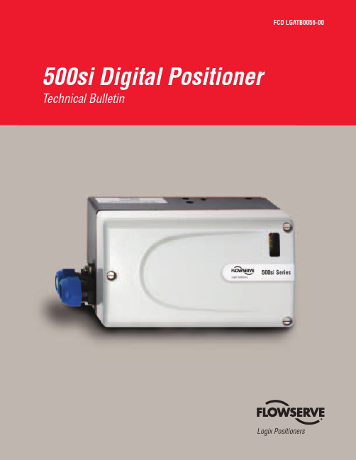
-PHJY 1PTJUJPOFSTOptional gauge block moduleFlow Control DivisionLogix PositionersFCD LGATB0056-01 500si Digital Positioner 3FeaturesAdvantagesLogix 510siLogix 520siEasy CommissioningCommissioning is performed by simply setting a few switches and pressing the QUICK-CAL button. The Direct User Interface provides local access to positioner control without requiring multi-level menus, a handheld communicator or laptop computer.••Local Status LEDsLEDs, visible from a distance, indicate the positioner’s current status without removing the cover.••Internal Diagnostic CodesLEDs provide instant information relating to internal diagnostic codes. These codes indicate to the user positioner status and alarms without the need for a handheld communicator or laptop computer.••Fast and Simple Confi gurationWith its unique Direct User Interface, the Logix 500si positioner provides fast and easy confi guration. Local confi guration switches allow the user to set all basic parameters for positioner operation, such as output characteristic (e.g. equal percent, linear or custom), air action, signal direction, gain, tuning, etc. Calibration typically takes less than one minute.••Jog CalibrateThe jog calibrate function allows the user to easily and quickly calibrate the positioner on all actuators without physical stroke stops.••Auto TuneAdapting the response of the Logix 500 series positioner to a particular valve confi guration is as simple as pressing a button. The Logix 500 positioner has a built in auto-tuning function that, when enabled, quickly adjusts the response to match the valve and actuator. If the automatic tuning does not match the needs of the process, it can be modifi ed in seconds by selecting a less aggressive auto-tune (gain) setting from the local user interface. Once set, the tuning is fi xed until the next time an auto-tune is performed.••HART CommunicationUsing industry standard HART protocol, the Logix 500si positioner can use existing handheld communicators and supply extensive information to mainte-nance database software packages.•Low Air ConsumptionState-of-the-art piezo technology combined with inner-loop feedback produces high-performance control with minimal air consumption.••21-Point CharacterizationWith SoftTools software or a handheld communicator, a custom 21-point char-acterization curve can be generated that can be used to change the response of the positioner to meet the process requirements.•DiagnosticsSoftTools allows the user to gather detailed diagnostic information regarding valve performance and positioner condition, in addition to the LED status codes.•Two-Stage Control DesignPositioner uses two-stage control to provide faster response and tighter control.••Confi guration LockoutConfi guration lockout option in SoftTools permits users to perform automatic ibration procedures without modifying existing confi guration and tuning set-tings.•NAMUR and VDI/VDE NAMUR and VDI/VDE mounting interfaces provide direct standardized mounting to various linear or rotary actuators. Brackets are available for non-NAMUR actuators.••Compact and Lightweight The positioner’s compact design allows it to be installed on smaller actuators.••Multiple Limit Switch OptionsModular design allows reliable, inexpensive, non-contact, high resolution limit switches.••Self-Adjusting LinkageConnecting the position feedback linkage of the Logix 500 series positioner to an actuator is simplifi ed by the ability of the feedback arm to rotate 360° and adapt to any shaft rotation angle between 15° and 100° at any orientation.••510si and 520si Digital PositionersFeatures and AdvantagesQUICK-CAL ButtonGain SelectorFlow Control DivisionLogix PositionersFCD LGATB0056-01 500si Digital Positioner 5The Flowserve Logix 510si positioner is a digital positioner operated with an analog 4–20 mA input signal. The positioner consists of three main modules: 1) the microprocessor-based electronic control module with optional analog feedback and direct local user interface switches; 2) the piezo-valve-based electro-pneumatic converter module; and 3) the infi nite resolution valve position sensor.Figure 3 shows the principle of operation of the Logix 510si. The analog 4–20 mA command signal is passed to the microproces-sor, where it is compared to the measured valve stem position. The control algorithm in the processor performs dual gain calculations and produces an output command to the analog piezo valve, which drives the pneumatic amplifi er. The pilot valve position in the pneu-matic amplifi er is measured and relayed to the inner loop controlcircuit. This two-stage control provides for a more responsive andtighter control than is possible with a single-stage control algorithm.The pneumatic amplifi er controls the airfl ow to the actuator. The change of pressure and volume of the air in the actuator causes the valve to stroke. As the valve approaches the desired position, the difference between the commanded position and the measured posi-tion becomes smaller and the output to the piezo is decreased. This, in turn, causes the pilot valve to close and the resulting airfl ow to decrease, which slows the actuator movement as it approaches the new command position. When the actuator has reached the desired position, the pneumatic amplifi er output is held at zero, which holds the valve in a constant position.510si Series Digital PositionersPrinciple of OperationFigure 3: Logix 510si Digital Positioner SchematicLocal User Interface4–20 mA Inner LoopPiezo ControlStrokeInner Loop Position FeedbackFilter / Regulator for Supply Air22–87 psi (1.5–6.0 bar)Air Supply∑-Micro-processorGainPressure RegulatorPiezo ValvePneumatic AmplifierControl Valve+4–20 mAInput Output(0ptional)1) Digital Control Circuit2) Electro-pneumatic Converter Module3) Valve Position SensorFlow Control DivisionLogix Positioners6 500si Digital Positioner FCD LGATB0056-01The Flowserve Logix 510si digital positioner automatically provides users with comprehensive, detailed diagnostic information. Colored LEDs continuously indicate positioner status or health during normal operation or calibration. This information can be used to determine whether a valve is functioning properly or needs service.In total, 28 different status situations can be displayed, e.g.:• Normal operation, no internal problems • Device is undergoing calibration • Calibration error detected • Deviation error detected • Internal electronic board errorLinearity < ± 1.0%Resolution < 0.3%Repeatability < 0.5%Deadband< 0.5%Operating TemperatureStandard-4–176°F -20–80°C Low-40–176°F -40–80°CTransport and Storage Temperature-40–176°F -40–80°COperating Humidity 0–100% non-condensing TypeNEMA 4, NEMA 4X, IP65Input Signal Range 4–20 mA Compliance Voltage 6.0 VDC Voltage Supply (maximum)30 VDC Minimum Required Operating Current3.6 mAFeedback Shaft RotationMinimum 15°, Maximum 90°, 40° recommended for linear applicationsSupply Air Quality Free from moisture, oil and dust per IEC 770 and ISA-7.0.01Input Pressure Range 22–87 psi (1.5 to 6.0 bar)Air Consumption (steady state)0.047 SCFM @ 22 psi 0.08 Nm 3/********0.071 SCFM @ 87 psi 0.120 Nm 3/********Output Pressure Range 0–100% of supply air pressure Output Flow Capacity (@ input pressure)1.41 SCFM @ 22 psi2.4 Nm 3/********4.12 SCFM @ 87 psi 7.0 Nm 3/********Housing Material Cast aluminum,powder-painted Soft Goods Nitrile Weight2.7 lb. (1.2 kg)With Pressure Gauges 3.5 lb. (1.6 kg) Without Pressure Gauges2.7 lb. (1.2 kg)ATEXFlow Control DivisionLogix Positioners8 500si Digital Positioner FCD LGATB0056-01The Flowserve Logix 520si positioner is a digital positioner that incorporates the HART protocol for communication. The positioner consists of three main modules: 1) the microprocessor-based electronic control module includes HART communications and direct local user interface switches; 2) the piezo-valve-based electro-pneumatic converter module; and 3) the infi nite resolution valve position sensor.The basic positioner operation is best understood by referring to Figure 5. The complete control circuit is powered by the two-wire, 4–20 mA command signal. The HART module sends and receives the Frequency Shift Key (FSK) HART digital communications super-imposed over the 4–20 mA signal wires, providing two-way digital communications to the microprocessor.The analog 4–20 mA command is passed to the microprocessor, where it is compared to the measured valve stem position. Thecontrol algorithm in the processor performs dual gain control calcu-lations and produces an output command to the analog piezo valve, which drives the pneumatic amplifi er. The pilot valve position in the pneumatic amplifi er is measured and relayed to the inner loop con-trol circuit. This two-stage control provides for more responsive and tighter control than is possible with a single-stage control algorithm.The pneumatic amplifi er controls the airfl ow to the actuator. The change of pressure and volume of the air in the actuator causes the valve to stroke. As the valve approaches the desired position, the difference between the commanded position and the measured position becomes smaller and the output to the piezo is decreased. This, in turn, causes the pilot valve to close and the resulting fl ow to decrease, which slows the actuator movement as it approaches the new command position. When the valve actuator is at the desired position, the pneumatic amplifi er output is held at zero, which holds the valve in a constant position.520si Series Digital PositionersPrinciple of OperationLocal User Interface4–20 mA + HARTHARTInner Loop Piezo ControlStrokeInner Loop Position FeedbackFilter / Regulator for Supply Air22–87 psi (1.5 – 6.0 bar)Supply Air∑-Micro-processorGainPressure RegulatorPiezo ValvePneumatic AmplifierControl Valve+1) Digital Control Circuit3) Valve Position Sensor2) Electro-pneumatic Converter ModuleFigure 5: Logix 520si Digital Positioner SchematicFlow Control DivisionLogix PositionersFCD LGATB0056-01 500si Digital Positioner 9The Flowserve Logix 520si digital positioner automatically provides users with comprehensive, detailed diagnostic information. Colored LEDs continuously indicate positioner status or health during normal operation or calibration. This information can be used to determine whether a valve is functioning properly or needs service.Some of the conditions detected include:• Normal operation, no internal problems • Cycle limit is exceeded• Travel limit is exceeded• Device has exceeded upper or lower travel limits • Device is undergoing calibration • Calibration error detected • Manual override in progress • Board current too high• Internal temperature limit exceededLinearity < ±1.0%Resolution < 0.1%Repeatability < 0.2%Deadband< 0.2%Operating TemperatureStandard-4–176°F -20–80°C Low-40–176°F -40–80°CTransport and Storage Temperature -40–176°F -40–80°C Operating Humidity 0–100% non-condensing TypeNEMA 4, NEMA 4X, IP65Input Signal Range (with HART)4–20 mA Compliance Voltage (with HART signal)12.0 VDC Voltage Supply (maximum)30 VDC Minimum Required Operating Current3.6 mAFeedback Shaft RotationMinimum 15° Maximum 90°40° recommended for linear applicationsSupply Air Quality Free from moisture, oil and dust per IEC 770 and ISA-7.0.01Input Pressure Range 22–87 psi (1.5 to 6.0 bar)Air Consumption (steady state)0.047 SCFM @ 22 psi 0.08 Nm 3/********0.071 SCFM @ 87 psi 0.120 Nm 3/********Output Pressure Range 0–100% of supply air pressure Output Flow Capacity (@ input pressure)1.41 SCFM @ 22 psi2.4 Nm 3/********4.12 SCFM @ 87 psi 7.0 Nm 3/********Housing Material Cast aluminum, powder-painted Soft Goods Nitrile Weight2.7 lb. (1.2 kg)With Pressure Gauges 3.5 lb. (1.6 kg) Without Pressure Gauges2.7 lb. (1.2 kg)ATEXitself for mounting to any type of diaphragm actuator. Brackets are available for the most500si Series Digital PositionersOrdering InformationOption Choice(s)Description Example5Communication 1No remote communications2 2HARTElectronic hardware options0Standard diagnostics0siCertifi cations 02Intrinsically safe Class I, Div 1, Groups A, B, C, D (Factory Mutual/CSA)14 08Nonincendive, Class I, Div 2, Groups A, B, C, D14General purpose15EEx ia IIC, ATEX II 1 GHousing and brand label W Flowserve: Aluminum, black with white coverW Y Flowserve: Aluminum, black with yellow coverB Flowserve: Aluminum, blackA Accord: Aluminum, blackThreaded connections 1½ NPT conduit, ¼ NPT pneumatic1 2M20 conduit, ¼ NPT pneumatic3½ NPT conduit, ¼ NPT pneumatic, ¼ NPT aux vent4M20 conduit, ¼ NPT pneumatic, ¼ NPT aux ventFeedback shaft D Standard Linear - D shaftD R Standard VDI/VDE 3845 Rotary shaft (NAMUR)Operating temperature S Standard -4°F to 185°F (-20°C to 85°C)S E Extended -40°F to 185°F (-40°C to 85°C)Language E EnglishEF FrenchG GermanRotary indicator 0No indicator0 F FlatD DomedSpecial options0None0Add-in Electronic Circuits 0No add-in circuits0 F4–20 mA positon feedback (510 base model now)Limit switchesNOTE: Switches only available for General Purpose (-14) and ATEX certi-fi ed product (-15). Approvals pending in North America (i.e. FM/CSA).0No switches1 1Mechanical limit switch2Reed switch3Namur V3 type proximity switch, P+F NJ2-V3-N4Slot type NAMUR sensor, P+F SJ2 S1N5Slot type NAMUR sensor, P+F SJ2 SN6Slot type NAMUR sensor, P+F SJ2NAuxiliary Options (To be ordered seperately)Manifold options DA Double actingDA GM Gauge manifoldVE VDI/VDE 3847 semi-integrated manifoldGauge options 0No gauges1 1Output, psi (bar, kPa) Stainless with brass internals2Output + Supply, psi (bar, kPa) Stainless with brass internals3Output, psi (bar, kPa) Stainless with stainless internals4Output + Supply, psi (bar, kPa) Stainless with stainless internals5Output, psi (kg/cm2) Stainless with brass internals6Output + Supply, psi (kg/cm2) Stainless with brass internals7Output, psi (kg/cm2) Stainless with stainless internals8Output + Supply, psi (kg/cm2) Stainless with stainless internalsFCD LGATB0056-01 500si Digital Positioner 15Flowserve Corporation has established industry leadership in the design and manufacture of its products. When properly selected, this Flowserve product is designed to perform its intended function safely during its useful life. However, the purchaser or user of Flowserve products should be aware that Flowserve products might be used in numerous applications under a wide variety of industrial service conditions. Although Flowserve can (and often does) provide general guidelines, it cannot provide specifi c data and warnings for all possible applications. The purchaser/user must therefore assume the ultimate responsibility for the proper sizing and selection, installation, operation, and maintenance of Flowserve products. The purchaser/user should read and understand the Installation Operation Maintenance (IOM) instructions included with the product, and train its employees and contractors in the safe use of Flowserve products in connection with the specifi c application.While the information and specifi cations contained in this literature are believed to be accurate, they are supplied for informative purposes only and should not be considered certifi ed or as a guarantee of satisfactory results by reliance thereon. Nothing contained herein is to be construed as a warranty or guarantee, express or implied, regarding any matter with respect to this product. Because Flowserve is continually improving and upgrading its product design, the specifi cations, dimensions and information contained herein are subject to change without notice. Should any question arise concerning these provisions, the purchaser/user should contact Flowserve Corporation at any one of its worldwide operations or offi ces. 6.8(173.5)2.5(63.5)1.1(28.6)0.7(17.7)1/2" NPT or M20 X 1.50.9 (23.9)2.4 (60)3.8 (96.5)0.5(11.9)0.9(23.9)3.9(100)0.5 (11.9)M80.4(10)1.9(47)1.1(28.6)1.1(28.6)0.7(17.7)0.4(10)0.2(4.8)1/4" NPT0.8(19.9)0.4(10)M8M6500si Series Digital PositionersDimensional DrawingsFigure 18: Logix 500si Digital Positioner Dimensional DrawingsVDI/VDE 3845 (NAMUR) shaftFor more information about Flowserve Corporation, visit www.fl or call USA 1-800-225-6989.FLOWSERVE CORPORATION FLOW CONTROL DIVISION1350 N. Mountain Springs Parkway Springville, UT 84663 USA Phone: 801 489 8611Facsimile: 801 489 3719www.fl Flowserve Australia, Pty. Ltd.14 Dalmore DriveScoresby, Victoria 3179AustraliaPhone: 613-9729-2633Facsimile: 613-9729-2644Flowserve Singapore 12 Tuas Avenue 20Singapore 638824Telephone: +65 862 3332Facsimile: +65 862 4940© 2004 Flowserve Corporation, Irving, Texas, USA. Flowserve is a registered trademark of Flowserve Corporation. FCD LGATB0056-01 Printed in USA.。
HOBO Rain Gauge Smart Sensor 用户手册说明书

Rain Gauge Smart Sensor (S-RGx-M002) Manual 14091-H The rain gauge smart sensor is designed to work with HOBO® stations. The smart sensor has a plug-in modular connector that allows it to be added easily to a HOBO station. All sensor parameters are stored inside the smart sensor, which automatically communicates configuration information to the logger without the need for any programming or extensive user setup.
Specifications Measurement Range 0 to 12.7 cm (0 to 5 in.) per hour, maximum 4000 tips per logging interval
Calibration Accuracy ±1.0% at up to 20 mm/hour (1 in./hour) Resolution 0.01 in. (S-RGA-M002) or 0.2 mm (S-RGB-M002) Calibration Requires annual calibration: can be field calibrated or returned to the factory for re-calibration
Operating Temperature Range 0° to 50°C (32° to 122°F), survival -40° to 75°C (-40° to 167°F) Environmental Rating Weatherproof Housing 15.24 cm (6 in.) aluminum collector and base Mechanism Tipping bucket; stainless steel shaft with brass bearings Dimensions 22.8 cm height x 15.4 cm diameter (9 x 6 in.), 15.4 cm (6.06 in.) receiving orifice
Statox 505 传感头操作手册说明书

Statox 505 Sensor HeadOperations ManualStatox 505 Sensor HeadOperations Manual1SAFETY INSTRUCTIONS 32STATOX 505 CONSTRUCTION 43INSTALLATION AND CONNECTION 5 3.1Warning 5 3.2Installation 5 3.3Electrical connection 63.3.1Statox 505 cable connection 73.3.2Connection diagram with Statox 501 Control Module in the 2-wire mode 83.3.3Connection diagram with Statox 501 Control Module in the 3-wire mode 103.3.4Connection diagram with Statox 502/503 Control Module in the 2-wire mode 123.3.5Connection diagram with Statox 502/503 Control Module in the 3-wire mode 134START –UP AND SERVICE 14 4.1Start - up and measuring mode 15 4.2Setting the realtime clock 16 4.3Setting the “service mode“ ou tput signal 17 4.4Calibrating the sensor 18 4.5Prooftest 20 4.6Info menu 21 4.7Test menu 225SENSOR REPLACEMENT 236MAINTENANCE 247SPARE PARTS AND ACCESSORIES 248STATUS- AND ERROR MESSAGES 25 8.1Status messages 25 8.2Error messages 26 9TECHNICAL DATA 27 9.1General transmitter data 27 9.2Sensor specific data 28 10CE-DECLARATION OF CONFORMITY 2921 Safety InstructionsThe Statox 505 sensor head is certified as explosion-proof safety equipment for group II category 2.The intended use is the measurement of toxic gas and oxygen concentration. Due to its intrinsically safe design it is safe to install and operate this product in zone 1 and zone 2.All relevant sensor parameters will be set automatically as soon as the sensor is connected.The following safety guidelines must be observed in particular:∙When installing and connecting the transmitter, the safety relevant electrical parameters and the protection class of the sensor head must comply with local standards (e.g. IEC 60079-14).∙If installed in a hazardous area, the power supply of the sensor heads must be intrinsically safe.Recommended products see connection diagrams in chapter 3.3 and in chapter 7 (accessories).∙The sensor head may only be operated within the specified environmental conditions.∙Damaged or not tightly closed housings may cause malfunction or loss of accuracy.All of the above warnings must be observed. Incorrect installation or connection will void the explosion proof rating and thus be dangerous to life and assets.34 2 Statox 505 constructionThe housing cover is attached with 4 bayonet screws. To open it, just turn these screws 90° counter - clockwise. The cover is secured to the housing with a steel strap.1 Mounting plate with 4 holes φ 10 mm2 Push buttons3 Display4 LED5 Programming interface (not for customer use)6 Cable terminal X17 Ground terminal8 Clamp for cable shield 9 cable gland M16x1,510 Sensor cover including filter support 11Securing strap for sensor cover167113 Installation and connection3.1 WarningIf the sensor head is installed in hazardous areas, the power supply must be intrinsically safe. Observe the safety - relevant specifications of sensor head, cable and barrier respectively intrinsically safe repeater.Caution:Do not install the sensor unless the sensor head has been connected to the power supply.The following specifications must be observed:U o, I o, C o, L o :certified repeater specificationsU i, I i, C i, L i : sensor head specifications (→ technical data)C L = cable capacity in pF/mL L = cable inductivity in nH/ml = cable length in mThe allowable cable length is defined in most cases by the cable capacity:l max = C o / C L (C i is negligible).Recommended cable type: see chapter 3.3.3.2 InstallationInstall the sensor head sensor downwards. Use stainless steel screws or insulate screws from mounting plate to avoid corrosion. In case of potential static voltage, ground the sensor head.The sensor head can be mounted to a wall with2 or 4 screws without opening the housing:Alternatively it can be mounted to a horizontalor vertical pipe. Statox 505 pipe mounting kitsare listed in chapter 7 accessories.5Statox 505 drilling plan and dimensions3.3 Electrical connection∙Use cable with 2 or 3 x ≥ 0,75 mm² with close - mashed shield, outer diameter ca. 6 mm(e.g. type Oelflex 415 CP3 X 0,75).∙Advantage of 3 - wire operation:In the two wire mode, the output signal for service and system failure is the same (2 mA).In the 3 - wire mode you can differentiate between “service” (non - critical = 2 mA) and “failure”(critical = 0 mA).∙If connecting the Statox 505 sensor head to a Statox 501 control module, follow the connecting diagrams in the chapters 3.3.2 and 3.3.3.If connecting the Statox 505 sensor head to a Statox 502/503 control module, follow the connecting diagrams in the chapters 3.3.4 and 3.3.5.If connecting the Statox 505 sensor head directly to a PCS, observe the following connecting diagram.In case of 2-wire-mode use only terminals 1 and 2.Statox 505 PCS63.3.1 Statox 505 cable connection∙Use cable with 2 or 3 x ≥ 0,75 mm² with close – mashed shield, outer diameter ca. 6 mm(e.g. type Oelflex 415 CP3 X 0,75).∙Do not install the sensor unless the sensor head is connected to the power supply.∙Run 20 cm (8 in) of cable through the cable gland.∙Strip the cable down to the shield. (A)∙Shorten the shield to 10 mm (0,4 in) and bend it backward. Make sure it does not touch the housing. (B)∙Connect the wires as shown in the schematics. The terminal is plugged in. Remove it for easy installation.∙Draw the cable back until the shield matches the clamp∙Fasten the cable gland.∙Secure the shield with the clamp. Good contact provides best protection from electromagnetic interference.∙Plug the terminal in.∙When the sensor head is connected to the power supply, the LED starts flashing for a short time and the display shows the software index.∙Now install the sensor (see chapter 4).A B C123Ø 5 - 7 mmX173.3.2 Connection diagram with Statox 501 Control Module in the 2-wire modeBefore connecting the sensor head, select the appropriate program. Refer to the Statox 501 operations manual and the program overview.3.3.2.1 2-wire mode installation in non hazardous areas83.3.2.2 2-wire mode installation in hazardous areasCaution: Incorrect connection of the intrinsically safe repeater might destroy it. Please take care for correct polarity and avoid short circuits.Repeater forms a current source: the terminal numbers on the drawing below refer to repeater type 9160/13-11-11s from manufacturer R.Stahl Schaltgeräte GmbH (or Siemens type 7NG4124-0AA00).It requires an extra power supply and forms a current source at clamps 1 and 2.A1 A2 SF 4-20mA A1 A2 Horn SFRepeater forms a current sink: the terminal numbers on the drawing below refer to repeater type9160/13-10-11s from manufacturer R.Stahl Schaltgeräte GmbH. It requires an extra power supply and forms a current sink at clamps 1 and 2.A1 A2 SF 4-20mA A1 A2 Horn SF93.3.3 Connection diagram with Statox 501 Control Module in the 3-wire modeBefore connecting the sensor head select the appropriate program. Refer to the Statox 501 operations manual and the program overview.3.3.3.1 3-wire mode installation in non – hazardous areasA1 A2 SF 4-20mA A1 A2 Horn SF103.3.3.2 3-wire mode installation in hazardous areasCaution: Incorrect connection of the intrinsically safe repeater might destroy it. Please take care for correct polarity and avoid short circuits.Repeater forms a current source: the terminal numbers on the drawing below refer to repeater type 9160/13-11-11s from manufacturer R.Stahl Schaltgeräte GmbH (or Siemens type 7NG4124-0AA00). It requires an extra power supply and forms a current source at clamps 1 and 2.Repeater forms a current sink: the terminal numbers on the drawing below refer to repeater type 9160/13-10-11s from manufacturer R.Stahl Schaltgeräte GmbH. It requires an extra power supply and forms a current sink at clamps 1 and 2.operations manual and the program overview.3.3.4.1 2-wire mode installation in non-hazardous areas3.3.4.2 2-wire mode installation in hazardous areasCaution : Incorrect connection of the intrinsically safe repeater might destroy it. Please take care for correct polarity and avoid short circuits. The terminal numbers on the drawing refer to repeater type 9160/13-11-11s from manufacturer R.Stahl Schaltgeräte GmbH (or Siemens type 7NG4124-0AA00). It requires an extra power supply and forms a current source at clamps 1 and 2. Plant = hazardous area Non hazardous area Power supply X1 Power supply X1 RepeaterStatox 502/503 Statox 502/503operations manual and the program overview.3.3.5.1 3-wire mode installation in non-hazardous areas3.3.5.2 3-wire mode installation in hazardous areasCaution : Incorrect connection of the intrinsically safe repeater might destroy it. Please take care for correct polarity and avoid short circuits.The terminal numbers on the drawing refer to repeater type 9160/13-11-11s from manufacturer R.Stahl Schaltgeräte GmbH (or Siemens type 7NG4124-0AA00). It requires an extra power supply and forms a current source at clamps 1 and 2. Plant = hazardous area Non hazardous area Power supply X1 Power supply Repeater X1 Statox 502/503 Statox 502/5034 Start –up and serviceSensor head keyboard:Press UP and DOWN at the same time to enter the menu.Increase / decrease the displayed parameter.Press and hold button for fast forward.RESET: One level up in the menu.ENTERTimeout: The sensor head returns automatically into the measuring mode if no key is pressed for more than 5 minutes.4.1 Start - up and measuring mode∙As soon as the sensor head is connected to the power supply, it starts a self test and shows the software index.∙Now install the sensor and filter. Please observe the handling instructions in chapter 5 !∙Remove the yellow protection cap from the sensor cover!∙As soon as the sensor is connected, the sensor head displays the parameter version, the gas to be detected, the measuring range and the best before date of the sensor. As soon as zero has stabilized, the instrument goes into the measuring mode. The green LED starts flashing.As long as the sensor head is not ready, the output signal is in the system fail mode, i. e. 2 mA when operated in the 2 wire mode, 0 mA when operated in the 3 wire mode.∙When the sensor head has completed the start – up sequence, you can start setting the real time clock (see chapter 4.2) and the service mode output signal (see chapter 4.3).4.2 Setting the realtime clock∙The clock is set ex works to CET. Please set it to your local time to make sure you get correct protocols of calibration and alarms.∙The clock has a back-up battery to save the time setting when power is disconnected.∙The segments flashing can be set with the up / down buttons.∙You can leave the time set menu by pushing the reset button.4.3 Setting the “service mode“ output signal∙The following table shows the potential modes and outputs.Notice: During the sensor replacement in the REPLACE menu, the sensor head remains in the service mode - even if no sensor is connected!∙If the sensor head is operated as a safety relevant device according to EN 50402 (Functional Safety) the output in the service mode must be 2 mA !4.4 Calibrating the sensor∙ Sensor head and sensor must have the same temperature!∙ You need a Statox 505 calibration adapter (art.no. 570505), a gas tubing 4x1 mm (art.no. 556710) and span gas (acceptable gas concentrations see chapter 9.2). If the environment is not clean, you need synthetic air for zeroing.∙ In case the calibration fails for whatever reason, the sensor head will continue to operate with the existing parameters, but the display will alternate showing the measured value and ZERO ADJ or CALIB until a calibration procedure has been completed.∙ O 2-sensors do not require a zero adjustment, as their output in pure nitrogen is nearly 0 nA. The span calibration can be done with clean ambient air or synthetic air.Procedure∙ Affix the adapter on the sensor cover until it catches (clockwise rotation). ∙ Connect the calibration adapter to the span gas cylinder.∙ Enter the service menu and select code 11 to enter the calibration routine. Set Zero.∙ Push ENTER button. As soon as the display shows GAS ON, open the valve. The gas flow should be ca. 20 l/h (300 ml/min). If you want to avoid span gas to be released into the environment, you can connect an active carbon filter art.no. 806488 to the exhaust of the gas adapter. Make sure there is no pressure building up in the adapter!∙ The display will show GAS.IS.ON until the reading is stable. Then it will show CONCENT? Now press ENTER . The display will now show the concentration of the recently used span gas. If you have used a gas with different concentration, adjust with the up / down buttons and confirm with ENTER .∙ When the display shows DONE , press ENTER to display the present concentration. Now close the regulator and remove the calibration adapter (clockwise rotation).∙ To return to the measuring mode, press ENTER again. The green LED starts flashing. If you fail to press ENTER , the sensor head will return to the measuring mode automatically after a timeout of 5 minutes. Calibration adapter4.5 Prooftest∙ A prooftest provides a verification of the transmitter performance under field conditions. It must be performed in regular intervals, if the transmitter is used as a safety relevant device. As long as the menu “Prooftest” is active, the output signal is set to 2 or 4 mA. In case the entire alarm chain must be tested, this must be done in the measuring mode.∙You need the Statox 505 calibration adapter art.no. 570505, a gas tubing 4x1 mm , art.no. 556710 and span gas with a concentration within the measuring range, preferably close to the alarm threshold.∙Affix the adapter on the sensor cover until it catches (clockwise rotation).∙Connect the gas adapter to the span gas cylinder.∙Enter the service menu and choose code 99 to enter the proof test routine.∙As soon as the display shows PROOF, open the valve and press ENTER. The gas flow should be ca.20 l/h (300 ml/min). If you want to avoid span gas to be released into the environment, you canconnect an active carbon filter art.no. 806488 to the exhaust of the gas adapter. Make sure there is no pressure building up in the adapter!∙The display will show the present concentration. Wait until the signal is stable before reading.∙Close the gas regulator and remove the calibration adapter (clockwise rotation).∙Return to the measuring mode by pushing the RESET button, stepping upward in the menu until you reach the measuring mode.∙If a new calibration is necessary proceed according chapter 4.4.∙Special timeout: If you do not push a button for 30 minutes, the transmitter returns automatically to the measuring mode.∙ A 2- or 3-time LED flashing during the proof test signalizes a periodical hardware test.∙This menu provides information about alarm history and sensor parameters.∙The exposure recording starts as soon as the end of the measuring range is exceeded.You can access the most recent 3 alarm events (start, end of range and end). The alarm events are not listed chronologically. For oxygen sensors only: the exposure recording starts as soon as the measured value drops below the detectable limit (see chapter 9.2).∙The total exposure information (DOSIS) is not updated permanently. Exposure by calibration is neglected. The maximum exposure reading depends on the measuring range. It is either 9,99 or 99,9 or 999 ppm * min.∙The total exposure recording is inactive for oxygen sensors.∙The calibration factor is a parameter used by the microprocessor. It cannot be used to obtain information about the sensor signal.∙In order to check the signal loop, the sensor head can generate 4, 12 and 20 mA.Caution: this might trigger an external alarm!∙The display can be tested by displaying a sequence of fonts and patterns.∙The sensor head can also display temperature.5 Sensor replacementPlease observe the precautions to avoid electrostatic voltage, when handling electronic devices. To avoid the sensor from being removed, while exchanging data with the sensor head, enter the service menu before you remove it. In the menu REPLACE the sensor can be replaced without generating a system failure alarm (see chapter 4.3). During the sensor replacement the sensor head will remain in the service mode.Handling instructions:still remaining in the service mode. After pushing theENTER button, or after a timeout of 30 min the sensor6 Maintenance∙Clean the Statox 505 with a humid wipe. Do not use detergents, solvents or steam jet.∙Inspect the housing and the O-rings for damage and pollution so that gas can securely access the sensor.∙If the sensor head is used in extremely harsh environment, an extra spray shield can be installed.Calibrate the sensor with the spray shield installed. Contact Compur Monitors for technical support!∙If the Statox 505 sensor head is used as a safety relevant device in terms of functional safety standard (EN 50402, IEC 61508), a regular proof test is mandatory (see chapter 4.5).7 Spare parts and accessoriesSpare sensors and technical data see chapter 9.2 !8 Status- and Error messages 8.1 Status messages8.2 Error messagesIf there is no display at all, check fuse and polarity. Fuse replacement by authorised personnel only.Critical errors set the output signal to 2 mA in the 2 – wire mode or to 0 mA in the 3 – wire mode. Non critical errors normally occur during maintenance or calibration. They have no impact on the system status.9 Technical data9.1 General transmitter dataProduct name: Statox 505 TransmitterType: 5375Manufacturer: COMPUR Monitors GmbH & Co. KG, D-81539 München Measuring principle: electrochemicalOperating temperature: -30°C to +60°C / -22° F to 140° FStorage temperature: -30°C to +60°C / -22° F to 140° FHumidity: 0 to 99% r.h. (non condensing)Pressure: 900 to 1100 hPaAccuracy at calibration point: +/- 10%Power supply: 12 -28 VDC, max. 22mAConnection: 2- or 3-WireOutput signal: 4 - 20 mA, max. load 700 Ohm∙In service mode: 2 or 4 mA adjustable∙In system fail mode: 0 mA in 3 - wire mode, 2 mA in 2 - wire mode∙Overrange: 22 mADisplay: 8-digits, 14 segmentsDimensions (HxWxD): 225 x 180 x 90 mm / 8,9 x 7,1 x 3,5 in (incl. mounting plate) Weight: 1040 g / 36,7 ounce (incl. mounting plate)Housing material: ABS chromium plated / stainless steelProtection class EN 60529: IP 65Operation position: Sensor downwardsEMC: EN 50270ATEX: Ex ib IIC T4 (EN 60079-0 and EN 60079-11)Application: II 2 GEC type examination certificate: BVS 09 ATEX E 104Parameters: U i: max. 28 VDCI i:max. 93 mA , P i = 650 mWInternal capacity C i: neglectibleInternal inductance L i: neglectibleFunctional safety: SIL 2M ore detailed information with regards to functional safety seeStatox 505 functional safety document art.no. 570555.9.2 Sensor specific data10 CE-Declaration of conformitySpecifications are subject to change without notice, and are provided only for comparison of products. The conditions under which our products are used, are beyond our control. Therefore, the user must fully test our products and / or information to determine suitability for any intended use, application, condition or situation. All information is given without warranty or guarantee. Compur Monitors disclaims any liability, negligence or otherwise, incurred in connection with the use of the products and information. Any statement or recommendation not contained herein is unauthorized and shall not bind Compur Monitors. Nothing herein shall be construed as a recommendation to use any product in conflict with patents covering any material or device or its use. No licence is implied or in fact granted under the claims of any patent. Instruments are manufactured by Compur Monitors GmbH & Co. KG, Munich.The General Conditions of Supply and Service of Compur Monitors GmbH & Co. KG, Munich, are applicable.Compur Monitors GmbH & Co. KGWeißenseestraße 101D-81539 MünchenTel.: ++49/89/ 6 20 38 268Fax : ++49/89/ 6 20 38 184E-Mail:****************5375 000 998 07 09 / 02.19 570553。
501说明书

A1主要特点可编程模块化输入,可支持热电偶、热电阻、电压、电流及二线制变送器输入;适合温度、压力、流量、液位、湿度等多种物理量的测量与显示;测量精度高达0.3级。
具备数字校正、数字滤波及热电偶冷端自动补偿功能,免维护且使用方便。
支持多达四路报警功能,包括二路上限及二路下限报警,可以独立输出也可共用一路继电器输出。
支持温度变送输出功能,采用高精度电流输出模块X,综合变送精度达0.5级。
支持RS485通讯接口功能,安装S或S4模块可与上位机通讯,通讯协议与A1系列仪表兼容。
采用双显示器面板,设置参数及报警值时更方便直观,并可选择多种面板外型尺寸。
优质的软硬件设计,采用钽电容或陶瓷电容替代电解电容,具备比同级产品更低的电源消耗、更高的可靠性、稳定性及更宽广的温度使用范围;其电源及I/O端子均通过2KV/5KHz的群脉冲抗干扰实验。
100-240V全球范围使用的开关电源,具备防雷击和10秒防误接380VAC电源的防护功能。
2型号定义A1-501 A N X L2 N S4 - 24VDC①②③④⑤⑥⑦⑧这表示一台仪表:①基本功能为A1-501型仪表;②面板尺寸为A型(96×96mm);③辅助输入(MIO)没安装模块;④主输出(OUTP)安装X线性电流输出模块;⑤报警(ALM)安装L5双路继电器触电输出模块;⑥辅助输出(AUX)没有安装模块;⑦通讯(COMM)装有自带隔离电源的光电隔离型RS485通讯接口S4;⑧仪表供电电源为24VDC电源。
仪表型号中8个部分的含义如下:①表示仪表基本功能AI-501型测量显示报警仪表,具备热电偶、热电阻、mV、5V、10V等线性电压输入,测量精度为0.3级②表示仪表面板尺寸规格A面板96×96mm,开口92×92mm,插入深度100mmA2在A基础上增加25段4级亮度1%分辨率光柱,可指示测量值B面板160×80mm(宽×高),横式,开口152×76mmC面板80×160mm(宽×高),竖式,开口76×152mmC3在C基础上增加50段2级亮度1%分辨率光柱,可指示测量值D面板72×72mm,开口68×68mm,插入深度95mmD2面板48×48mm,开口45×45mm,插入深度95mmE面板48×96mm(宽×高),开口45×92mm,插入深度100mmF面板96×48mm(宽×高),开口92×45mm,插入深度100mm③表示仪表辅助输入(MIO)安装的模块:V24或V10,24V或10V电压输出,可供外部变送器、称重传感器等使用。
PCI-1711_user_manual中文版用户手册

3.2
I/O 接口 .......................................................16
3.2.1 针脚定义 ................................................16
图 3.1: PCI-1711/1731 的 I/O 接口针脚定义 ..............17
3.5.2 外部脉冲触发源连接 ......................................20
3.6
现场接线注意事项 ............................................... 21
第 4 章 软件概述 .............................. 23
图 2.1: 研华自动化软件安装界面.........................9
图 2.2: 研华自动化软件 - 分组选择.......................9
图 2.3: 研华自动化软件 - 安装选项......................10
图 2.4: 研华自动化软件 - 驱动按总线列表................10
A.1
模拟量输入 .................................................... 32
A.2
模拟量输出 (仅适用于 PCI-1711) ............................... 32
A.3
数字量输入 / 输出 .............................................. 33
5.4