《南海发利厨具公司保温柜作业指导卡》(xls)
燃气公司:各工种岗位操作指导卡
5.若要“手动”输出,将工作状态扳到“手动”,顺时针调节“手动输出调节”,使仪器输出电流达到欲控值,但此时仪器的限流、报警电路均失去作用。(平时,手动输出调节电位器应反时针旋到底,以免在由“自动”转“手动”时输出过大;)
程序与步骤
执行情况
检查和
准备
1、动火证件办理齐全,监护人到位。
2、氧气、乙炔瓶间距不小于5米,与明火散发点距离不小于10米。
3、检查焊接电源,控制系统是否有接地线或焊机外壳接地
4、检查焊接端坡口面管壁一定范围内铁锈、泥土、油漆等杂质是否去除干净(除锈至St2级)。
5、检查对焊接管线端面应与管子轴线是否垂直。
下令人:操作地点:时间:年月日时编号:
风险提示
违章操作、机械伤害、人身伤害、烫伤、火灾、爆炸、塌陷
应急处置
发生事故,立即救护伤者,报告并积极参与应急处置。
程序与步骤
执行情况
检查和
准备
1、选用合适的工具(扳手、水平尺、三角架、手动葫芦等)。
2、选用符合标准的配件:螺栓(套)、密封垫子。
3、检查核对阀门等设备、材料是否与设计相符。
管道安装操作
1、预制安装管道,清洁管道口壁
2、按标准对管道打坡口
3、安置好脚架和手动葫芦
4、吊装对口(严禁强力组对,错边不超过1mm)
5、监护焊工焊接
6、按公司要求进行焊口防腐
7、管道下沟(沟底平整,沟深符合要求)
8、监督检查管沟恢复(覆盖的沙土符合要求)
V Series 加热保温运输柜 产品说明书
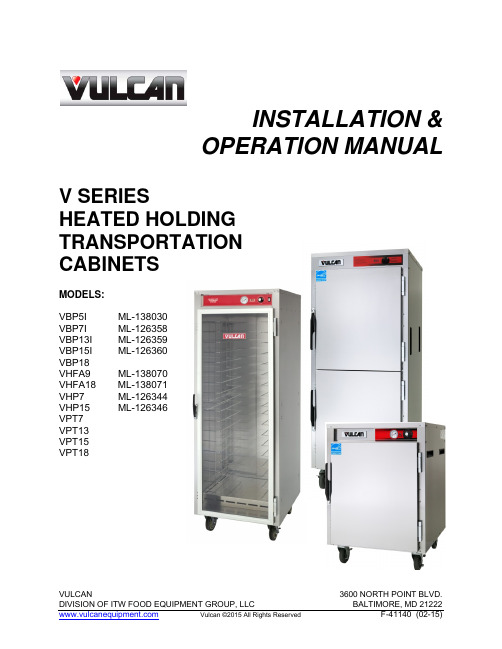
INSTALLATION &OPERATION MANUAL V SERIESHEATED HOLDING TRANSPORTATIONCABINETSMODELS:VBP5I ML-138030VBP7I ML-126358VBP13I ML-126359VBP15I ML-126360VBP18VHFA9 ML-138070VHFA18 ML-138071VHP7 ML-126344VHP15 ML-126346VPT7VPT13VPT15VPT18IMPORTANT FOR YOUR SAFETYTHIS MANUAL HAS BEEN PREPARED FOR PERSONNEL QUALIFIED TO INSTALL ELECTRICAL EQUIPMENT, WHO SHOULD PERFORM THE INITIAL FIELD START-UP AND ADJUSTMENTS OF THE EQUIPMENT COVERED BY THIS MANUAL.FOR YOUR SAFETYDO NOT STORE OR USE GASOLINE OR OTHERFLAMMABLE VAPORS OR LIQUIDS IN THEVICINITYOF THIS OR ANY OTHER APPLIANCE.Improper installation, adjustment,alteration, service, or maintenance cancause property damage, injury, or death.Read the installation, operating andmaintenance instructions thoroughlybefore installing or servicing equipment.IN THE EVENT OF A POWER FAILURE,DO NOT ATTEMPT TO OPERATE THIS DEVICETABLE OF CONTENTSIMPORTANT FOR YOUR SAFETY . . . . . . . . . . . . . . . . . . . . . . . . . . . . . . 1 GENERAL . . . . . . . . . . . . . . . . . . . . . . . . . . . . . . . . . . . . . . . . . . . . . . . . 3 INTRODUCTION . . . . . . . . . . . . . . . . . . . . . . . . . . . . . . . . . . . . . . 3 INSTALLATION . . . . . . . . . . . . . . . . . . . . . . . . . . . . . . . . . . . . . . . 3 ELECTRICAL REQUIREMENTS . . . . . . . . . . . . . . . . . . . . . . . . . . 5 VHFA9, VHFA18CONTROLS . . . . . . . . . . . . . . . . . . . . . . . . . . . . . . . . . . . . . . . 6 HOLDING INSTRUCTIONS . . . . . . . . . . . . . . . . . . . . . . . . . . . . 7 HOLDING SHUTDOWN . . . . . . . . . . . . . . . . . . . . . . . . . . . . . . . . . . 7 VBP, VPT SERIES – ELECTRONIC CONTROLSELECTRONIC CONTROLS . . . . . . . . . . . . . . . . . . . . . . . . . . . . . . . 8 HOLDING INSTRUCTIONS . . . . . . . . . . . . . . . . . . . . . . . . . . . . . . . 8 HOLDING SHUTDOWN . . . . . . . . . . . . . . . . . . . . . . . . . . . . . . . . . . 8 VBP, VHP, VPT SERIES – MANUAL CONTROLSCONTROLS . . . . . . . . . . . . . . . . . . . . . . . . . . . . . . . . . . . . . . . 9 HOLDING INSTRUCTIONS . . . . . . . . . . . . . . . . . . . . . . . . . . . . . . . 9 HOLDING SHUTDOWN . . . . . . . . . . . . . . . . . . . . . . . . . . . . . . . 10 HUMIDITY PAN . . . . . . . . . . . . . . . . . . . . . . . . . . . . . . . . . . . . . . . . 10 CLEANING . . . . . . . . . . . . . . . . . . . . . . . . . . . . . . . . . . . . . . . . . . . . . . . . 11 STAINLESS STEEL CARE . . . . . . . . . . . . . . . . . . . . . . . . . . . . . . . . . . . 11 PRESERVING & RESTORING AND HEAT TINT . . . . . . . . . . . . . . . . . . 12 MAINTENANCE . . . . . . . . . . . . . . . . . . . . . . . . . . . . . . . . . . . . . . . . . . . . 12 TROUBLESHOOTING . . . . . . . . . . . . . . . . . . . . . . . . . . . . . . . . . . . . . . . 13 SERVICE & PARTS INFORMATION . . . . . . . . . . . . . . . . . . . . . . . . . . . . 13GENERALINTRODUCTIONVulcan Heated Holding Transport Cabinets are produced with quality workmanship and material. Proper installation, usage, and maintenance of your cabinet will result in many years of satisfactory performance.It is suggested that you thoroughly read this entire manual and carefully follow all of the instructions provided.The V Series Heated Holding Transport Cabinets provide an efficient means of transporting and holding bulk prepared foods at proper serving temperatures.INSTALLATIONBefore installing, verify that the electrical service agrees with the specifications on the rating plate located on the lower back corner of the cabinet. If the supply and equipment requirements do not agree, do not proceed with unpacking and installation. Contact your Vulcan-Hart Customer Service Department immediately.UNPACKING:The Cabinet was inspected before leaving the factory. The transportation company assumes full responsibility for safe delivery upon acceptance of the shipment. Immediately after unpacking, check for possible shipping damage to the cabinet.If the cabinet is found to be damaged, save the packaging material and contact the carrier within 15 days of delivery.Carefully unpack and place in a work accessible area as near the installation position as possible.1. Open the door and carefullyremove any packaging materialsand the retaining straps that holdthe tray slides and tray slideupright side supports. 2. Peel off vinyl protection film.3. STACKED UNITS ONLY:Stacked cabinets are stacked ontop of each other. One cabinetwill come with casters and astacking assembly on top.This cabinet requires two peopleto lift and should be placed insidethe stacking kit that was shippedwith the bottom cabinet. Stackingkits fit only one way between thecabinets. If for any reason eitherone or both cabinets do not fitwithin the stacking kit provided,please contact the servicedepartment at 414-434-4716.4. Remove universal tray slides frombox.5. Install tray slides in the cabinet.Make sure the hook on the end ofthe tray slide is up. (Fig. 1)Fig. 1VPT MODEL DOORS:The doors should always be hinged to open opposite of each other. Please refer to Figure 2.Top View of CabinetHingeHingeFig. 2The doors should never be hinged to open on the same side of the cabinet. Please refer to Figure 3.Fig 3CLEANING:The cabinet should be thoroughly cleaned prior to putting into service.Use a mild soap and water solution to clean the interior of the unit. Never use harsh chemicals or abrasive pads to clean the unit.LOCATION:For efficient cabinet operation, choose a location that will provide easy loading and unloading without interfering with the final assembly of food orders.The installation location must allow a minimum of 4” clearance for servicing and proper operation . (Fig.4)Fig. 4ELECTRICAL REQUIREMENTS ELECTRICAL CODES & STANDARDS:The cabinet must be installed in accordance with:In the United States of America:1. State and Local Codes.2. National Electrical Code, ANSI/NFPA-70 (latest edition.) Copiesmay be obtained from: TheNational Fire ProtectionAssociation, 1Batterymarch Park,Quincy, MA 02269.1-617-770-3000In Canada:1. LocalCodes.2. Canadian Electrical Code, CSAC22.1 (latest edition.) Copiesmay be obtained from: TheCanadianStandardAssociation.www.csa.caELECTRICAL CONNECTIONS:The cabinet is factory wired for either 110/120 volt or 208/240 volt, single phase operation. All 110/120 volt cabinets are equipped with an 8 foot cord and NEMA 5-15 plug as standard equipment. All 208/240 volt cabinetsare equipped with a 8 foot cord and NEMA 6-15 plug. VHFA18 cabinets are equipped with an 8 foot cord and NEMA5-20 plug as standard equipment. The cord and plug supplied is a suitable durable cord with a molded three-prong plug, and is provided with a proper strain relief.All cabinets are equipped with a three-prong plug. Itis imperative that this plug must be connected into a properly grounded three-prong receptacle. If the receptacle is not the proper grounding type, contact an electrician. Do not remove the grounding prong from this plug.Verify that the power source matches the Serial Data Plate locatedon the lower back corner of the cabinet and the plug configuration before the connection is made. (Fig. 5) Always uncoil power cord and remove from cord wrap when unit isin operation.(Fig. 5)VHFA9, VHFA18 OPERATION INSTRUCTIONSVHFA9 & VHFA18 - MANUAL CONTROLSThe Cabinet and its parts are hot. Be very careful when operating, cleaning, or servicing the cabinet.POWER FULL-RANGE FAN ON/OFFINDICATOR THERMOSTATSWITCHLIGHTTHERMOMETER HEAT INDICATOR LIGHT(Fig. 6)Power Indicator Light:The Red Power Indicator Light indicates power is supplied to the cabinet. The red light will stay lit as long as the cabinet is plugged in.Heat Indicator Light:The Amber Heat Indicator Light indicates the heating element(s) are heating. The amber light will stay lit as long as the heating element(s) are engaged. Once the predetermined temperature is achieved, the heating element(s) will begin to cycle. During this period, the amber light will turn on and off. Fan On/Off Switch:The Fan On/Off Switch turns the fan on only. The use of the fan is optional. Turn on fan if forced air holding is desired.Thermometer:The Thermometer indicates the interior temperature of the cabinet. Thermostat:The Thermostat turns power on to the heating element(s). The thermostat setting is from 1 to 10. The greater the thermostat setting number, the higher the temperature.It is recommended that prior to placing the cabinet in operation, that it be preheated at the highest temperature setting for a period of 30 to 45 minutes.VHFA9 & VHFA18 HOLDING INSTRUCTIONSThe Cabinet and its parts are hot. Be very careful when operating, cleaning, or servicing the cabinet.Always uncoil power cord and remove from cord wrap when plugging cord in power source..Once the cabinet has been connected to the appropriate power source, the cabinet is ready for operation.1. Begin by turning the thermostatdial to the number 5. This willcause the heating element(s) tostart heating. Once the red lightis lit, the thermostat dial can beturned to the desired setting. 2. Switch the Fan switch to On ifforced air holding is desired. Theuse of the fan is optional. Use ofthe fan keeps the temperatureeven throughout the cabinet.3. Wait approximately 25 minutesfor the cabinet to preheat.4. Load Hot food pans with hot,cooked food into cabinet.VHFA9 & VHFA18 HOLDING SHUTDOWNWhen the use of the holding cabinet is completed:The Cabinet and its parts are HOT. Be very careful when operating, cleaning, or servicing the cabinet.1. Turn the thermostat to the Offposition.2. Keep the fan switch in the Onposition. This helps remove theexcess humidity from the food product.3. Allow cabinet to cool down completely.4. Unplug power cord.5. Clean cabinet according toinstructions in this manual.This cabinet is not intended to reheat or cook food. Food must be cooked and at a safe serving temperature prior to being placed in the cabinetThe operator should always monitor the food product to insure that it remains ata proper temperature .VBP, VPT Series - ELECTRONIC CONTROLS (Effective 2015)OPERATION INSTRUCTIONSVBP SERIES ELECTRONIC CONTROLSThe Cabinet and its parts are hot. Be very careful when operating,cleaning, or servicing the cabinetAlways uncoil power cord and remove from cord wrap whenplugging cord in power source.(Fig. 7) ELECTRONIC TEMPERATURE CONTROL KNOBSCREENELECTRONIC TEMPERATURE SCREEN:The Electronic Temperature Screen displays desired temperature. It only displays the internal temperature when the control knob is pushed.CONTROL KNOB:By turning the Control Knob you turn the unit ON or OFF, and you set the desired temperature. By pushing the Control Knob you display the internal temperature of the unit.VBP, VPT ELECTRONIC CONTROLS HOLDING INSTRUCTIONSTo Turn Unit On:1. Turn knob ¼ turn clockwise and pause 2 seconds.2. Turn knob clockwise to set desired temperature.3. Circulating Fan and Cooling Fan will turn on automatically whenthe unit starts to heat. 4. Wait approximately 25 minutesfor the cabinet to preheat. 5. Load Hot food pans with hot, cooked food into cabinet. Push Control Knob to display or monitor internal temperature of unit.This cabinet is not intended to reheat or cook food. Food must be cooked and at a safe serving temperature prior to being placed in the cabinetThe operator should always monitor the food product to insure that it remains at a proper temperature .VBP, VPT ELECTRONIC CONTROLS HOLDING SHUTDOWNTo Turn Unit Off: 1. Turn knob counter clockwise until“OFF” is displayed.2.Both Circulating Fan and Cooling Fan will remain on until unit cools.VBP, VHP,& VPT SERIES - MANUAL CONTROLSOPERATION INSTRUCTIONSVBP, VHP, & VPT SERIES CONTROLSThe Cabinet and its partsare hot. Be very careful when operating, cleaning, or servicing the cabinet.(Fig.8)THERMOMETER THERMOSTAT HEAT INDICATOR LIGHTHeat Indicator Light:The Amber Heat Indicator Light indicates the heating element(s) are heating. The light will stay lit as long as the heating element(s) are engaged. Once the predetermined temperature is achieved, the heating element(s) will begin to cycle. During this period, the light will turn on and off.Thermometer:The Thermometer indicates the interior temperature of the cabinet.Thermostat:The Thermostat turns power on to the heating element(s). The thermostat setting is from 1 to 10. The greater the thermostat setting number, the higher the temperature. (Fig. 9)VBP, VHP, & VPT SERIES HOLDING INSTRUCTIONSThe Cabinet and its parts are hot. Be very careful when operating,cleaning, or servicing the cabinet.Always uncoil power cord and remove from cord wrap whenplugging cord in power source.1. Begin by turning the thermostat dial to the number 5. This will cause the heating element(s) to start heating. Once the red light is lit, the thermostat dial can be turned to the desired setting. The circulating fan will engage afterapproximately 1 to 2 minutes of operation. 2. Wait approximately 25 minutes for the cabinet to preheat. 3. Load Hot food pans with hot, cooked food into cabinet.This cabinet is not intended to reheat or cook food. Food must be cooked and at a safe serving temperature prior to being placed in the cabinetThe operator should always monitor the food product to insure that it remains at a proper temperature .VBP, VHP, & VPT SERIES HOLDING SHUTDOWNThe Cabinet and its parts are HOT. Be very careful when operating, cleaning, or servicing the cabinet.1. Turn the thermostat to the Off position.2. Allow cabinet to cool down completely.3. Unplug power cord.4. Clean cabinet according toinstructions in this manual.The circulating fan will continue to operate until the cool down period is complete. Do not unplug cabinet until the circulating fan has stopped operating.HUMIDITY PANHUMIDITY PAN (VBP & VHP Option)The humidity pan is designed to provide additional humidity to the holding cabinet interior when required. It is suggested that the humidity pan only be used when a moist environment is required.1. The humidity pan should only be used when filled with water. Using thehumidity pan without water will damage the black non- s pill sponge material.2. Place the humidity pan directly on the bottom of the cabinet and fill with water.While in use monitor the humidity pan and refill when necessary.3. Remove humidity pan when not in use or when transporting cabinet.CLEANINGAlways unplug electrical power supply before cleaning.DAILY:1. Unplug electrical power supply.2. Allow warmer to cool before cleaning.3. Clean the interior of the cabinetwith a mild soap and water.Never use harsh chemicals orabrasive pads to clean the cabinet. 4. Rinse and dry with a soft dry cloth. 5. Clean the exterior of the cabinetwith a clean damp cloth.HEAVY-DUTY CLEANING:For heavy-duty cleaning, use warm water, a degreaser, and a plastic, stainless steel, or Scotch-Brite pad. Never rub in a circular motion -- rub gently in the direction of the steel grain. Always rinse thoroughly.STAINLESS STEEL CARECLEANING:Stainless Steel contains 70 – 80% iron, which will rust if not properly maintained. Stainless Steel also contains 12 – 30% chromium, which forms an invisible passive, protective film that shields against corrosion.If the protective film remains intact, the stainless steel will remain intact. However, if the film is damaged, the stainless steel can break down and rust. PREVENTIVE CARE:To prevent stainless steel break-down, follow these steps:1. Never use any metal tools,scrapers, files, wire brushes,or scouring pads.2. Never use steel wool – whichwill leave behind particles that will rust.3. Never use acid-based orchloride containing cleaning solutions– which will break down the protective film.4. Never rub in a circular motion.Always rub gently in the directionof the steel grain.5. Never leave any food productsor salt on the surface. Manyfoods are acidic. Salt contains chloride.PRESERVING & RESTORING:Special stainless steel polishing cleaners can preserve and restore the protective film.Preserve the life of stainless steel with a regular application of a high-quality stainless steel polishing cleaner, as a final step to daily cleaning.If signs of breakdown appear, restore the stainless steel surface. First, thoroughly clean, rinse, and dry the surface. Then, on a daily basis, apply a high-quality stainless steel polish according to manufacturer’s instructions. HEAT TINT:Darkened areas, called “heat tint,” may appear on stainless steel exposed to excessive heat. Excessive heat causes the protective film to thicken. This is unsightly, but is not a sign of permanent damage.To remove heat tint, follow the routine cleaning procedure. Stubborn heat tint will require heavy-duty cleaning.To reduce heat tint, limit the exposure of equipment to excessive heat.MAINTENANCEThe Cabinet and its parts are Hot. Be very careful when operating, cleaning, or servicing the cabinet.Always unplug electrical power supply before servicing the cabinet.For Service, contact the Vulcan-Hart offices listed in this manual.NOTES:V SERIES -HEATED HOLDING CABINETS F-41140 (02-15)TROUBLESHOOTINGSERVICE & PARTS INFORMATIONTo obtain Service and Parts information concerning this model, contact the Vulcan Service Department at the address listed on the front cover of this manual or refer to our website: for a complete listing of Authorized Service and Parts depots.Customer Service 800-814-2028Service866-688-5226TechnicalParts 866-688-5226ServiceWhen calling for service, have the model number and serial number available.。
厨房管理表格模板
厨房管理表格模板厨房管理表格1、厨房经理每日检查表厨房经理检查时间:年月日分类检查内容优中差各岗位必查内容按要求验收购进物品质量、数量。
计划进货,保证供应。
禁购不识、不合法原材料。
厨房设备、设施是否完好,安全。
员工工衣、厨帽是否完整、洁净。
重点菜品、新推菜品、汤料的抽检合格率。
严防不合格菜品出堂下班后各加工间安全、卫生检查原材料加工是否合理、质量是否新鲜菜品的份量是否准确、装盘是否美观下班后各原材料、食品的保管和遮盖、严防异物掉入调料各种调料新鲜、准备充足、整体清洁卫生。
各种汤料、按标准投料掌握各种汤料熬制火候燃、灶、锅具的安全使用及完好下班后各种汤料遮盖、严防异物掉入,各种调料按要求保管各种用具摆放有序小吃小吃的加工符合卫生要求小吃品的色泽一致、大小均匀,符合出堂要求小吃要求新鲜、无异味加工间用具摆放整洁冰柜食品按要求遮盖保管,摆放有序,冰柜运转正常,达到所需温度粗加工严禁对不合格产品进行加工各种原材料摆放整齐、分类明确各种原材料整理、清洁有序加工后各种原材料干净、无异味。
符合精加工要求,按要求保管和遮盖、严防异物掉入。
精加工各种原材料按要求进行加工。
不同原材料的刀工处理。
严禁对不合格产品进行加工。
冰柜食品摆放、进出有序,无血水,无异味。
正确使用各种机具及机具清洁卫生的保持。
配菜员菜品清洁卫生,符合出堂要求。
各种菜品分类摆放整齐、按特性分类保管。
各类用具摆放整齐,清洁卫生。
菜品装盘份量按标准执行。
2、厨房成本计算表品名单位进价净料率净率成本份量成本价售价毛利率3、厨房菜品验收记录表日期品名计划数实收数备注4、厨房仓库设备安全例检项目表检查填表人:检查日期/时间:年月日分检查正故备分检查事项正故备分检查事项正故备类事项常障注类常障注类常障注门门牌天然气分段控制仓库货架摆放位置螺丝管道两端连接货物摆放距离把手、锁固定卡子是否分类摆放地面清洁开关阀门柜架间通道距离裂痕高压连接皮管货物摆放标准平面光滑厨具刀具摆放是否放置消防器材工清洁墩子摆放排气系统碗柜餐具摆放应急照明台平面光滑餐具(盘子)摆放灯光照明系统开水器整机外观餐具(不锈钢)摆放电源线路系统运行情况碗柜隔断灯具插座系统豆浆整机外观碗柜滑门开关使用情况机运行情况洗碗间洗碗槽整体外观物品存放切肉机整机外观开关阀门有无住宿设施运行情况热水器外观有无配电开关、箱制冰机整机外观热水器运行情况仓库门运行情况排水管道仓库窗热水器整机外观地沟清洁门锁运行情况地板清洁有无安全隐患厨房(设施、设备)使用、保养规定分类品名使用保养保养人风幕机大堂开空调时打开,营业结束时关闭每周1~2次整体清洁,由专人进行保养配菜员立式冰柜冷藏:春冬季调至3~4档冷冻:秋夏季调至6~7档每日下班前除尽血水,残渣,每周1~2次除冰保养墩子师、配菜员、小吃师制冰机客人用餐酒水、饮料等用。
厨房管理标示卡
负责范围
菜架、菜墩、刀具、菜筐以及墙面、地面
责任人
梁惠同
清理时间
每餐结束后
检查时间
每餐下班前
下班行六常
1.处理不需要的东西;
2.所有物料、文件、工具、仪器以及私人物品都放在应放的地方;
3.根据卫生清洁计划、标准做清洁工作;
6.顾客现场点用酒店海鲜时,应有礼貌,积极主动的向客介绍品种及特性,烹调方法及营养价值。
7.在顾客选取海鲜后及时确保品种并沥水放置在周转筐内,进行控水至顾客满意并过秤记录。
8.在处理去绳销售的羔、肉蟹时,注意操作方法,以免操作者受伤,对于凶猛的黑鱼、元鱼、鲨鱼要用专用塑料袋套用。
负责范围
鱼缸的缸体、供氧控温设备、海鲜冰台、电子称以及墙面、地面
2.上班期间,严格遵循酒店仪容仪表的标准要求;
3.负责范围的物品及工具必须严格遵循六常管理法的名、家制度及管理标准要求,做到任何物品有名、有家、有数量,物品的标签朝外并严格按照物品的最高、最低限量做好物品的控制管理;
4.负责范围的卫生须遵循酒店制定的卫生管理标准,随时保持地面干燥、无卫生死角;
5.接收货物过程中,剔除不合格品,并对毛蛤、花蛤、牡蛎、毛蟹等进行冲洗,按温度、盐度不同入贝类池。
标准与规范要求
1.根据酒店工作的实际需要上下班;
2.上班期间,严格遵循酒店仪容仪表的标准要求;
3.负责范围的物品及工具必须严格遵循六常管理法的名、家制度及管理标准要求,做到任何物品有名、有家、有数量,严格按照物品的归位做好物品的控制管理;
4.负责范围的卫生须遵循酒店制定的卫生管理标准,随时保持地面干燥、无卫生死角。
保温三单两卡范本

保温三单两卡范本保温三单两卡范本一、保温三单范本1. 保温工程验收单范本保温工程验收单项目名称:施工单位:施工日期:完工日期:验收日期:一、基本情况1. 工程地点:2. 工程规模:3. 施工内容:二、验收标准1. 施工图纸和设计要求是否符合实际施工情况?2. 施工材料是否符合国家标准和设计要求?3. 施工质量是否达到设计要求?4. 是否按照规定的施工程序进行施工?5. 是否按照规定的时间节点完成施工任务?三、检查内容1. 施工图纸和设计要求的核对情况。
2. 施工材料的检查情况。
3. 施工质量的检查情况。
4. 施工程序的检查情况。
5. 完成时间节点的检查情况。
四、结果评定1. 符合验收标准的项目:2. 不符合验收标准的项目:五、建议意见1. 对于不符合验收标准的项目,提出整改意见。
2. 对于已经整改完毕的项目,提出确认意见。
六、其他事项(此处可填写其他需要注意或记录的事项)2. 保温工程结算单范本保温工程结算单项目名称:施工单位:施工日期:完工日期:结算日期:一、基本情况1. 工程地点:2. 工程规模:3. 施工内容:二、结算标准1. 施工图纸和设计要求是否符合实际施工情况?2. 施工材料是否符合国家标准和设计要求?3. 施工质量是否达到设计要求?4. 是否按照规定的施工程序进行施工?5. 是否按照规定的时间节点完成施工任务?三、结算内容1. 施工图纸和设计要求的核对情况。
2. 施工材料的核对情况。
3. 施工质量的核对情况。
4. 施工程序的核对情况。
5. 完成时间节点的核对情况。
四、费用计算1. 工程材料费用总计:2. 人员劳务费用总计:3. 设备租赁费用总计:4. 其他费用总计:五、结算结果1. 应付款项总计:2. 已付款项总计:3. 未付款项总计:六、其他事项(此处可填写其他需要注意或记录的事项)3. 保温工程质量评定单范本保温工程质量评定单项目名称:施工单位:施工日期:完工日期:评定日期:一、基本情况1. 工程地点:2. 工程规模:3. 施工内容:二、评定标准1. 施工图纸和设计要求是否符合实际施工情况?2. 施工材料是否符合国家标准和设计要求?3. 施工质量是否达到设计要求?4. 是否按照规定的施工程序进行施工?5. 是否按照规定的时间节点完成施工任务?三、评定内容1. 施工图纸和设计要求的核对情况。
KitchenAid KFGC506JSS05 烹饪随身师房具说明书

GAS RANGE MODELS:KFGC506JSS05(Stainless)Illus.No.Part No.Description1Literature PartsW11508863Use and Care GuideW11508887InstallationInstructionsW11184759Guide,InternetConnectivityW11575703Diagram,Wiring(Cooktop)W11565467Tech SheetW11364680Guide,Quick Start 2W10892995Assembly,ValveManifold(Left Front,Left Rear,Center Rear)W10893005Assembly,ValveManifold(Center Front,RightFront,Right Rear) 3W10903729Switch,Harness4W11121194Bracket,Manifold5W11121317Module,Spark Illus.No.Part No.Description6W10115843Cover,Ignition77101P426-60Screw8W10892073Tube,Manifold Supply(Left)W10892334Tube,Manifold Supply(Right)Illus.No.Part No.Description9Box,Burner(NotServiced)FOLLOWING PARTSNOT ILLUSTRATEDW11448063Harness,Main(36in)W11200332Harness,CooktopW10780278Harness,Door LockW11200325Harness,CommunicationW11242785Harness,WIFI313438Clip,HarnessW10624584Cord,Power4450800Screw,GroundingW10253333Bracket,Anti-Tip7101P485-60Screw,Anti-Tip KitW11238042Kit,LP ConversionW11311196Ignitor Wire,Wire-Electrode BakeW11311197Ignitor Wire,Wire-Electrode BroilIllus.No.Part No.Description1W11106881Panel,Cabinet Side(Left)W11106880Panel,Cabinet Side(Right)2W10892774Assembly,OrificeHolder(Left Front)W10892492Assembly,OrificeHolder(Left Rear)W11159467Assembly,OrificeHolder(Center Front)W10892725Assembly,OrificeHolder(Center Rear)W10892731Assembly,OrificeHolder(Right Front)W10892477Assembly,OrificeHolder(Right Rear)3W10892422Orifice,Main(17.4K)(Left Front,RightFront)W10892419Orifice,Main(15K)(Left Rear,Right Rear,Center Front)W10892435Orifice,Simmer(2.6K)(Left Front,RightFront)W10892438Orifice,Simmer(5K)(Center Rear)4W11238757Igniter(Left Front,RightFront)W10892340Igniter(Center Front,CenterRear)W11114379Igniter(Left Rear,Right Rear)Illus.No.Part No.Description5W11291183Burner,Grate(WithWok Ring)6W11291179Burner,Grate7W11323261Screw(8-18X1in)W11323309Screw(8-18X1/2in)8W11281269Barrier,ApplianceManager9W11436337Interface,User10W11205795Cover,WIFI Outer11W10883433Bezel(Rear Burners)12W10881642Bezel(Front Burners)13Cap,BurnerW11121390Black(Includes6)14W10891746Spreader,Flame(High)(Left Front,RightFront)W10891974Spreader,Flame(Low)(Left Rear,CenterFront,Right Rear)W10891978Spreader,Flame(AUX)(Center Rear)15W11036559Spring Clip,Range16Knob,Oven ModeW11500865Stainless17W11543345Manager,Appliance(Powermax)18Panel,CooktopW11038235Black(Left)W11038257Black(Center)W11038248Black(Right)19W11130078Antenna,WIFI20Trim,T-StripW10271524BlackIllus.No.Part No.Description21W10130760Bracket,MovingConsole(Left)W10130759Bracket,MovingConsole(Right)22W11328357Screw23W10877950Panel,Console24Knob,SingleW10912166Stainless25Knob,DualW10883172Stainless26W10896366Assembly,Light Pipe27Bezel,OvenW11500871Stainless28Knob,OvenTemperatureW11500868Stainless29W11205794Cover,WIFI Inner30W11241511Button Assembly,Oven Light31W11476245Trim,Island32W10323250Insert,Island Trim337101P426-60Screw34W11241510Button Assembly,Oven Start353400814Screw367101P624-60Screw37W11042504Bumper,Grate38W11110768Assembly,WIFIModule39W10568405Assembly,SpeakerIllus.No.Part No.Description1W11394782Kickplate2W11324988Back,Chassis3W10138054Assembly,Roller4W11095572Duct,Bottom(36in)57101P426-60Screw69760860Leveler7W10908710Base,Leveling Leg84449743Screw9W11369237Cabinet,ApplianceManager10W10115869Shaft,Long11W10115793Shaft,Short12489504E-Ring Illus.No.Part No.Description13W11181648Tube,PressureRegulator14W11087493Support,Channel15W11115330Gasket,Oven(36in)16W11050145Duct-Chassis,Rear17W11368831Channel,Wire18W11362015Retainer,Gasket(9inLong)19W11324985Top,Chassis20W11040801Chassis,Bottom21W11103333Panel,Back Top22W11034133Panel,Back BottomIllus.No.Part No.Description23W11096823Bracket,PressureRegulator24W10896959Regulator,Pressure25W11036559Spring Clip,Range26W11106341Drawer,ApplianceManager27W11199181Cover,Foot(Left)W11199178Cover,Foot(Right)28W11190223Bracket,BakeAlignment29W10145680Valve,DualIllus.No.Part No.Description14450249Thermostat(TOD)2W10622170Probe,Sensor3W10351278Bumper and Screw4W10830016Latch,Motorized5W10145743Tube,Vent6W11223932Assembly,Oven Light7W10169756Lens,Light8W10169757Bulb,Light9W11096294Receiver,Hinge(Left) 10W11096293Receiver,Hinge(Right)11Liner,Oven(NotServiced)12W11102297Chassis,Side(Left) W11102296Chassis,Side(Right)Illus.No.Part No.Description137101P426-60Screw14W10160858Cover,Latch153196176Screw16W11192749Frame,Front173196560Screw18W10308051Box,Broil197101P434-60Screw20W11182863Electrode,Broil21W11205400Electrode,Bake22W10145744Support,Bake Pan2312992902Screw24W10317437Bracket,Broil Standoff25W10878504Burner,Bake26W10311335Burner,Broil27W10308040Bracket,Bake BurnerIllus.No.Part No.Description28W10311009Insulation,Broil Cover29W10310985Cover,Broil30W11109238Tube,Broil31W11106980Tube,Bake32W11107279Tube,Gas33W10145362Bracket-Board,DSI34W10511278Module,Spark DSI35W10496809Pan,Oven BottomFOLLOWING PARTSNOT ILLUSTRATEDW10282811Insulation,WrapW11108226Insulation,Back,36inW10299356Insulation,Bottom3400968NutVENTING PARTSVENTING PARTSIllus.No.Part No.Description1W11106956Cover,Channel2W11105221Vent,Cooling Top(30in)3W11200129Blower4W11091676Vent,Cooling Bottom(30in)Illus.No.Part No.Description5W11109518Plate,Cooling Latch6W10115855Holder,Strain Relief77101P426-60Screw8W11047754Bracket,Blower Mount9W10145363Duct,Primary Air(30in)Illus.No.Part No.Description10W10246087Insulation,Chimney11W10246086Retainer,Insulation12W10340579Vent,Chimney Box(30in/36in)133400805Screw(Zinc)14W10919715GasketIllus.No.Part No.Description1W11036772Liner,Door2W10884823Insulation,Door3W11036791Glass,Inner4W11194820Retainer,Glass5W11096978Hinge,Door(Left) 6W10607120Screw Illus.No.Part No.Description7W11194814Frame,Glass8W10898280Screw9W10656499Screw10W11389307Assembly,Outer Door(Includes Handle)11W11362710Door HandleAssemblyIllus.No.Part No.Description12W11197830Bracket,Handle13W10518672Badge14W10276043Screw15W11361073Medallion,Handle16W10162096Screw17W11096977Hinge,Door(Right)Illus.No.Part No.Description19755543Jack,Meat Probe2W10282821Insulation,ConvectionCover3W10822069Rack,Oven4W11496903Rack,Sliding Oven5W11033111Nut,Locking6W11212180Baffle,Convection Illus.No.Part No.Description7W10631506Motor,Convection8W10631503Blade,Fan9W10261523Plate,Fan10W10631504Nut,Acorn(LH)11W11098505Element,ConvectionHeat124449154ScrewIllus.No.Part No.Description139755542Probe,Temperature14W10720084Screw15W10739592ScrewOPTIONAL PARTS(NOT INCLUDED) Illus.No.Part No.DescriptionACCESSORIESW11042467Spray,Stainless SteelCleaningW10355051Cleaner,Cooktop30-48KITRC Gas Range ConnectorKitBacksplashW1028544836-in With Shelf4396923Broiler Pan and Grid4396096RB Griddle。
Eaton 115393 产品说明书

Eaton 115393Eaton Moeller series NZM - Molded Case Circuit Breaker. Remote operator, 24-30VDC, standardSpécifications généralesEaton Moeller series NZM remote operator1153934015081151257150 mm 105 mm 105 mm 1.25 kg IEC UL/CSA RoHS conformUL (File No. E140305) CE marking UL listedCSA-C22.2 No. 5-09 CSA (Class No. 1437-01) UL489CSA (File No. 22086) IEC60947UL (Category Control Number DIHS) CSA certifiedNZM2-XRD24-30DCProduct NameCatalog Number EANProduct Length/Depth Product Height Product Width Product Weight Compliances CertificationsModel CodeIs the panel builder's responsibility. The specifications for the switchgear must be observed.1.1 x UsNZM2100 ms0 VMeets the product standard's requirements.Is the panel builder's responsibility. The specifications for the switchgear must be observed..85Does not apply, since the entire switchgear needs to be evaluated.Meets the product standard's requirements.24 V450 W (24 - 30 V DC)Meets the product standard's requirements.0 VMeets the product standard's requirements.Is the panel builder's M2-XRD24-30DCIL01219025ZDA-CD-nzm2_xrDA-CS-nzm2_xreaton-circuit-breaker-remote-operator-nzm-remote-operator-dimensions.eps10.11 Short-circuit ratingOperating voltage - maxFrameSignal duration of remote operator at switch off - minRated control supply voltage (Us) at AC, 50 Hz - min10.4 Clearances and creepage distances10.12 Electromagnetic compatibilityVoltage tolerance - min10.2.5 Lifting10.2.3.1 Verification of thermal stability of enclosuresRated control supply voltage (Us) at DC - minPower consumption10.2.3.2 Verification of resistance of insulating materials to normal heatRated control supply voltage (Us) at AC, 50 Hz - max10.2.3.3 Resist. of insul. mat. to abnormal heat/fire by internal elect. effects10.8 Connections for external conductors eCAD model Instructions d'installation mCAD modelSchémasLifespan, mechanical20000 operationsClosing delay110 ms - 170 msVoltage rating24 - 30 V DCSwitch drive typeMotor drive10.9.2 Power-frequency electric strengthIs the panel builder's responsibility.Special featuresSliding switch for "Auto" or"Manual"Max. number auxiliarycontacts: 2 standardauxiliary contacts, 1 trip-indicating auxiliary switchesCannot be combined withswitch-disconnector PN...Cannot be combined withmechanical interlockDo not install M22-CK11(20/02) dual auxiliarycontacts in the centerauxiliary contact slot inNZM2-XRDVoltage tolerance - max1.1Rated control supply voltage (Us) at AC, 60 Hz - min0 V10.7 Internal electrical circuits and connectionsIs the panel builder's responsibility.Terminal capacity (solid/flexible conductor)18 - 14 AWG0.75 mm² - 2.5 mm² with ferrule10.10 Temperature riseThe panel builder is responsible for the temperature rise calculation. Eaton will provide heat dissipation data for the devices.Rated control supply voltage (Us) at DC - max30 V10.9.3 Impulse withstand voltageIs the panel builder's responsibility.Number of polesThree-pole/Four-poleTypeAccessoryRemote operator, standard10.2.2 Corrosion resistanceMeets the product standard's requirements.10.6 Incorporation of switching devices and componentsDoes not apply, since the entire switchgear needs to be evaluated.10.2.4 Resistance to ultra-violet (UV) radiationMeets the product standard's requirements.10.2.7 InscriptionsMeets the product standard's requirements.Breaking time110 ms - 170 ms10.5 Protection against electric shockDoes not apply, since the entire switchgear needs to be evaluated.Rated control supply voltage (Us) at AC, 60 Hz - max0 VSignal duration of remote operator at switch on - min100 msUsed withNZM2(-4)N(S)2(-4)Operating voltage - min0.85 x UsNumber of operations per hour - max12010.13 Mechanical functionThe device meets the requirements, provided the information in the instruction leaflet (IL) is observed.10.2.6 Mechanical impactDoes not apply, since the entire switchgear needs to be evaluated.Eaton Corporation plc Eaton House30 Pembroke Road Dublin 4, Ireland © 2023 Eaton. Tous droits réservés.Eaton is a registered trademark.All other trademarks are property of their respectiveowners./socialmediaIs the panel builder's responsibility.Does not apply, since the entire switchgear needs to be evaluated.DC10.9.4 Testing of enclosures made of insulating material 10.3 Degree of protection of assembliesVoltage type。
各工种岗位作业指导卡

各工种岗位作业指导卡西气东输蒲县项目部作业指导卡清单序号名称 1 电焊工 HSE 作业指导卡 2 起重工 HSE 作业指导卡 3 管工 HSE 作业指导卡 4 铆工 HSE 作业指导卡 5 无损检测工 HSE 作业指导卡 6 电工 HSE 作业指导卡 7 仪表工 HSE 作业指导卡 8 钳工 HSE 作业指导卡 9 治安保卫 HSE 作业指导卡10 食堂炊事员 HSE 作业指导卡 11 火焊工 HSE 作业指导卡 12 起重司机 HSE 作业指导卡 13 运输司机 HSE 作业指导卡 14 防腐保温工 HSE 作业指导卡中国石油天然气第六建设公司西气东输蒲县项目部电焊岗位 HSE 作业指导卡编码:ZYLJ/西气东输-HSE-03-02-A 岗位名称:电焊工持卡人:岗位要求素质要求具有初中以上文化程度技能资质必须持有地方劳动部门颁发的焊工合格证工作经历 1 年以上岗位职责对上向谁负责向项目领导及各部室负责对下负责什么对铆工、管工、电工、仪表工负焊接作业安全责任权利和义务执行国家关于健康、安全、环保的政策、标准遵守电焊工安全技术操作规程和安全生产规章制度及项目部各种管理规定。
掌握个人防护用品正确使用和维护方法按规定正确使用穿戴好防护用品。
对管理人员违章指挥、强令冒险作业有权拒绝执行对危害生命安全和身体健康的行为有权提出批评、检举和报告。
上班前和工作中均不许饮酒不得在施工现场吸烟。
上下班穿越公路或乘坐卡车时要注意交通安全。
焊工有权对自己的劳动保障提出合理的要求同时拒绝违章作业。
对自己和他人的健康和安全负责。
操作指南工作程序引弧、熔池保持、电弧行走、收弧。
工作要求对本职工作尽职尽责不做与工作无关的事情。
在施工中互相监督对违章作业、违章指挥及时进行制止。
注意事项 1、做好焊机的保养工作。
2、高处作业时焊割下的料头必须采取可靠的防坠落措施。
3、焊机的地线禁止随处乱拉。
在焊接过程中如发生停电现象应立即将电源开关拉下防止发生意外事故。
- 1、下载文档前请自行甄别文档内容的完整性,平台不提供额外的编辑、内容补充、找答案等附加服务。
- 2、"仅部分预览"的文档,不可在线预览部分如存在完整性等问题,可反馈申请退款(可完整预览的文档不适用该条件!)。
- 3、如文档侵犯您的权益,请联系客服反馈,我们会尽快为您处理(人工客服工作时间:9:00-18:30)。
DOC.NO
REV 01PAGE 发行日期
计算时间标准时间3566
4279.2
NO
计算时间
145621380
3848
物料编号
数量
物料编号
数量
A025141S180238S020042S180408A020134A020624A020144A025162NO
项目
规格标准
检测方式
S1804840A0251521S180018A02517
2
2S18011163工具名称十字螺丝刀
手电钻打磨机4数量1
11
5
制订
审核
批准日期2006.4.28
示意图:
作业要点
882
486
取A02517铝导风口,将大口朝上,贴紧内侧板插入上面包托架中,上平面与柜侧板上端平齐,左右置中后,用小号争笔将其固定孔的中心标记在内侧板上,钻孔攻牙
M5后,用S18040螺丝套上弹垫,将铝导风板固定在内侧板上
取直锁与门铰安装在装饰条上,用螺丝固定
机型
45
S/S弹介 - M5铝导风口
S/S电钉- 1/4X1/2品质要求
磁性胶边压条B
下面包盘托架注意事项
S/S元头自攻1/2X6新加坡
上面包盘托架柜体组件
S/S元头机丝 - M5X10
直立柜门胶边S/S大平头螺丝 - 5X10磁性胶边压条A 外侧板装饰条用胶边压条固定孔模板靠平上下门框边,用小号色笔作好钻孔记号(每个柜20个孔)并钻好孔,S02004直立柜门胶边2条、A02014胶边压条B及A02013胶边压条A各4条,分别将其塞入门胶边上下第二层中,
再将胶边平辅在门框边上,内框与柜身内边平齐,然后将S18048自攻螺丝从胶边压条上拧进到门框里固定钻孔时,手要稳,钻头要正,并注意用力
取A02516下面包托架及A02515上面包托架各2件,将其上、下面包托架挂上,拧上螺
母,并把螺母点焊在螺杆上注意门铰边装饰条的装配方向(孔距长的一头朝柜上或下方向),盖好后不要遮住门铰固定
物料名称
物料名称
钻孔、攻牙
1
作业程序
作业描述将A02514柜体组件移至工作区,,将装饰条、门铰及门锁固定孔攻M5牙(每边11个),取A02062外侧板装饰条4条,将其盖在柜身上,两端用MS18023 S/S元头机丝,将其固定在柜身边上注意不要碰伤两侧
生产线
总装
GY-WI-02000共3页
作业指导卡作业名称工序NO 7A02516下面包托架
2A02062外侧板装饰条
3S02004直立
4A02013胶边
5A02014胶边
压条B
8A02517铝导风口
1A02514柜体组件
6A02515上面包托架
计算时间标准时间2400.3
2880.36
NO
计算时间
6312.3
76248
342
9504
10390
物料编号
数量
物料编号
数量
A025182A025201S020094S16110S10001
2A025121S1804436A025131NO
项目
规格标准
检测方式
S990090.100A0204111S180408S180018
2S02010 2.0003工具名称电钉机自制套筒
扳手手电钻螺丝批4数量1
11
11
5
制订
审核
批准
日期
2006.4.28
作业要点
示意图:
将A02512接水外盒,用S18040S/S大平头螺丝四粒分别套上M5弹介,将其固定在柜内控制箱底部后端,将A02041干湿口转换盖放置在接水内盒中,将接水内盒插入接水外盒中后,将设备推至待检测区
228
机型
11
S/S大平头螺丝 - 5X10
S/S弹介 - M5直立柜可调较锁
直立柜直锁 - 国产
接水外盒品质要求
S/S大平头螺丝 5X25
接水内盒
注意事项
螺丝胶 - 271-50ML 干湿口转换盖板
物料名称
物料名称
门组件
控制箱
直立柜门较 - 新款福乐斯胶条 - 3MM 取S12010直立柜直锁锁钩,将其贴在柜身外侧上端置中位置,用小号色笔将挂色固定孔中心标记在外侧板上,并钻孔再攻M5牙,然后用S18040S/S大平头螺丝固定在柜身两侧外侧板上
取A02520控制箱1台,在其底部与柜体顶部四周贴上一层福乐斯胶条,用刀片修去多余的胶条,将已贴好胶条的控制箱放在柜
部上,控制箱的出风口对准柜体的导风口,调整控制箱与柜体四周边对齐
将直立柜直锁挂片套入挂钩中,用小号色笔标记挂钩片的位置,并钻孔再攻M5牙,用
S18040S/S大平头螺丝固定在控制箱上,并扣紧直锁
作业程序
作业描述
取A02518门组件2件、S02009门铰4个、S10001直锁2个用S18044S/S大平头螺丝固定在门相应位置
把上工序门安装到柜体上并调整好门组件
F91414/HCPT双门双向直立保温柜作业名称工序NO 铝通风挂板及导风口
2
生产线
总装
1A02518门组件
2S02009直立柜门铰
3S10001直立柜直锁
4S02010直立柜直锁锁钩
5A02520控制箱6A02512接水外盒
7A02513接水内盒。